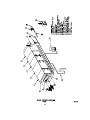
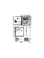
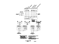
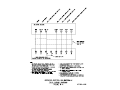
1
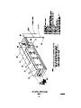
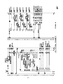
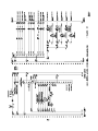
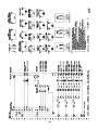
Air Boss ATS
(Air Treatment Systems)
ATS SERIES
•
•
•
INSTALLATION
OPERATION
SERVICE
Electrostatic Precipitators for
Commercial & Industrial
Applications
101 McNeill Road • Sanford, NC 27330
(919) 775-2201 • Fax: (919) 774-8771
(800) 884-0002
www.trioninc.com
MANUAL PART NO. 147207-001 • December 2002
TABLE OF CONTENTS
SECTION I DESIGN
For The System Design Engineer
Page
1. Introduction ................................................................................................................................ 1
2. General Description ................................................................................................................... 1
3. System Design and Layout........................................................................................................ 2
SECTION II INSTALLATION
For The Installing Contractor
1. Unpack and Inspect ................................................................................................................... 3
2. Position Air Cleaner Cabinet ..................................................................................................... 3
3. Connect Adjoining Ductwork .................................................................................................... 3
4. Mount Detergent System ........................................................................................................... 3
5. Connect Drain............................................................................................................................. 3
6. Connect Wash Water Supply..................................................................................................... 3
7. Mount Control............................................................................................................................. 4
8. Complete Wiring
A. High Voltage Wiring................................................................................................................ 4
B. Primary Wiring ........................................................................................................................ 4
9. Fire Suppression System (when factory supplied).................................................................. 4
10. Checkout for System Start-up .................................................................................................. 4
SECTION III OPERATION AND SERVICE
For The Maintenance Engineer
1. Introduction and Principle of Operation ................................................................................... 5
2. Initial Start-up ............................................................................................................................. 6
3. Wash Control and Detergent System Settings......................................................................... 8
4. Routine Maintenance ................................................................................................................. 9
5. Preventative Maintenance ......................................................................................................... 9
SECTION IV TROUBLESHOOTING
For The Maintenance Engineer
1. Trouble Shooting ..................................................................................................................... 11
2. Spare Parts ............................................................................................................................... 12
3. Trouble Reference Chart ......................................................................................................... 13
SECTION V REFERENCE
Illustrations and Drawings
Figure 1
Figure 2
Figure 3
Figure 4
Figure 5
Figure 6
Figure 6a
Figure 7
Figure 8
Figure 9
Figure 10
Figure 11
Figure 12
Figure 13
Figure 14
General Component Arrangement...................................................... 14
Unit Outline .......................................................................................... 15
Control Outline..................................................................................... 16
Detergent System Outline ................................................................... 17
Piping Schematic................................................................................. 18
Field Wiring Diagram ........................................................................... 19
Second Wash Section Field Wiring Diagram ................................... 19a
Fire Control System Outline................................................................ 20
ATS Control Schematic Page 1........................................................... 21
ATS Control Schematic Page 2........................................................... 22
AIR BOSS Control Schematic Page 1................................................. 23
AIR BOSS Control Schematic Page 2................................................. 24
ATS Remote Box Schematic Page 1................................................... 25
ATS Remote Box Schematic Page 2................................................... 26
Standard Single Section Sequence Timing ....................................... 27
SECTION I DESIGN
To provide access to the system components (except
the blower section), gasketed doors with push-button
latches and lift-off hinges are located 90 degrees to the
direction of airflow on one side of the cabinet. Access
preference should be noted when unit is ordered.
Access to the blower section is obtained by removing
the bolts retaining the discharge end panel.
FOR THE SYSTEM DESIGN ENGINEER
1. Introduction
ATS units are Air Treatment Systems designed to
efficiently remove a variety of contaminants from an air
stream. These contaminants my range from those found
in normal kitchen ventilation air to weld fumes or oils
and effluents from various manufacturing processes. A
range of units is available to clean specific air volumes.
The power supplies providing the necessary high
voltage for the electronic air cleaner and the controls
initiating and sequencing the wash cycle are housed in
a NEMA 12 enclosure designed for remote mounting. In
addition, the enclosure is a central junction for the
primary wiring.
Each unit is made up of mechanical and electronic “dirt”
collecting modules and efficient, trouble free operation
is absolutely dependent upon the periodic removal of
the collected contaminate from the cleaning elements.
Unit design simplifies this requirement.
The standard 16-gallon detergent system is furnished
as a completely assembled unit to be piped directly to
the wash water supply, into the wash manifold headers.
When properly installed, operated and maintained, the
ATS unit will effectively and efficiently perform its
designed task.
Note: 30 or 55-gallon detergent tanks are available as
an option.
2. General Description
The standard major components supplied with each
ATS unit are as follows:
• Base unit consisting of five modular sections: 1)
impinger, 2) electronic air cleaner 3) bag type media
filter 4) activated carbon adsorber and 5)
blower/motor.
• Washer control including high voltage power
supply(s) to be mounted remotely.
• Detergent system to be located remotely.
• Wash water supply-line strainer.
Note: Trion Tridex Detergent is specially formulated for
use with Trion electronic air cleaners. Use of other
cleaners and detergents, not specifically approved by
Trion, can cause possible failures in the unit and will void
any warranties on our equipment.
The strainer is to be installed in the wash water supply
line. Factory installed solenoid valves are located in the
piping inside the impinger and the electronic air cleaner
sections.
An optional chemical fire suppression system may be
specified to be included with the ATS unit if it is a
requirement of the application. The system available
from the factory must be completed at the
installation site by a qualified and authorized fire
control contractor. In addition to final hook-up, he will
complete tie-in with other existing systems, test, final
inspect and if necessary, coordinate his work with local
or other designated fire inspectors. The fire suppression
system includes strategically located, spray nozzles and
an electrical fire detection device to signal a control
head that opens a valve to discharge a chemical
cylinder. An auxiliary mechanical “Pull” is also supplied
to be installed at a remote location to manually activate
the system. The general contractor should coordinate
his work with that required by the fire control contractor.
Refer to fire control system outline drawing, Figure 7.
The impinger section contains impinger panels to collect
grease and liquid particulate, oscillating front and rear
wash manifolds and metal mesh pre-filters (and afterfilter when specified).
The electronic air cleaner section contains the ionizingcollecting cells to remove very fine particles; oscillating
front and rear wash manifolds and metal mesh prefilters and after-filters.
When a factory installed fire suppression system is
specified, both the impinger and electronic air cleaner
sections include spray nozzles. Fire control is usually
required in kitchen exhaust and similar applications.
The media section contains bag type filters providing
safety filtration for the electronic air cleaner in the event
of any accumulated blow-off or contaminant penetration
in the event of an electrical outage.
The following are standard options that may be
specified on the basic systems:
1.
2.
3.
4.
5.
Without carbon section
Without media section*
Without carbon and media sections
Without blower section
Additional electronic air cleaner section (double
pass unit)
6. 30 or 55 gallon detergent system
7. Perforated plate in lieu of the metal mesh filters
8. Fire suppression system
For odor control, the adsorber section contains the
activated carbon panels in a vee bank configuration.
With the exception of the wash manifolds and the
blower/motor, all the major components slide in and out
of the housing for ease of service.
1
for the safety of operating personnel. Any additional
access that may be provided in the system, where
there is access to high voltage, must be equipped with
such interlocks. Interlocks are readily available from
the factory.
*A carbon section without a media section is not
recommended by TRION.
3. System Design and Layout
(Refer to, or request, submittal drawings for dimensions
and data pertaining to a specific unit that is not included
in this manual).
Water wash drain lines from the cabinet drain basin
should be trapped or otherwise sealed against the
system pressure (in accordance with local codes).
Wash water to the unit must meet the volume required
for the specific unit involved, and between 35 PSIG Min.
– 50 PSIG Max. at full flow to provide proper spray
patterns from the wash nozzles. The wash water MUST
0
be Hot water (140 F recommended) and installed as
close as possible to the unit and detergent system.
The arrangement of the supplied components and the
general layout of the system will vary according to
application, adjoining equipment and available space.
However, there are several basic factors pertaining to
all installations that must be considered:
To maintain the selected cleaning efficiency, it is
important to assure that the total air volume (capacity in
CFM) is uniformly distributed across the entire face area
of the unit. The metal mesh filters, perforated plate or
mist suppressors, provide some resistance to effect
even air distribution. However, since most air ducts are
designed to handle air velocities greater than the rated
velocity of the air cleaner, it is necessary to properly
transition any attached ducting. If possible, a contraction
ratio of 1 in 3 (approximately 20°) should be maintained.
If space prohibits, turning vanes, air baffles or other
means may be utilized. Ducting – where attached to the
cabinet collars – should be gasketed, caulked or
otherwise made watertight. The bottom of the airentering duct should be reasonably flat and sloped
toward the impinger drain pan for a length of 18 inches.
This will assure that any wash water splashback is
returned to the drain basin. The ducting and duct
connections should be designed in accordance with
applicable code requirements.
NOTE: THE HOT WATER TANK IS NOT PROVIDED BY
TRION.
When applicable, the detergent system, the wash water
inlet piping and the drain lines must be protected from
freezing temperatures.
Each installation varies according to needs, but the
water wash control must be located indoors, out of the
weather, and as closed to the air cleaner as practical.
Ideal mounting height is at eye level for ease in reading
the instrumentation, and to facilitate service. The
instructions furnished for manually operating the fire
extinguishing system shall be posted conspicuously
near the control in the kitchen or well-occupied work
area.
For ease in maintenance and component removal,
adequate space, 39” Minimum Required, must be
provided in front of all access doors, motors, pump and
accessory equipment. Special consideration should be
given in this respect for installations where the unit is
suspended overhead. Catwalks or platforms should be
provided.
When there is a danger of rain, snow or debris being
drawn into the system with outside air, the make-up air
intake should be protected with rain louvers, hooding
and hardware cloth to prevent the rain, snow or debris
from entering the electronic air cleaner.
Some contaminants to be collected, such as oils in
vaporous state, must be condensed into particulate form
prior to entering the ionizing-collecting cells in order to
maintain the anticipated efficiency. Gases, vapors or
any non-particulate cannot be precipitated and will
therefore pass through the collecting elements. Any
condensing that takes place downstream from the air
cleaner defeats the purpose. By the same token, heavy
concentrations of water vapor, or other matter that
becomes highly conductive when condensed, must be
prevented from entering and/or condensing in the
electronic air cleaner to prevent electrical arc over and
shorting. The impinger module aids in this process and
will adequately handle light concentrations, however, it
is recommended to insulate upstream ducting
conveying warm air that is subjected to cold
temperatures on applications such as kitchen exhaust.
CAUTION
In addition to the above space requirement, installation
of the Model ATS in NFPA applications shall have a
clearance of at least 18 inches to a combustible
material, 3 inches to limited combustible material, and
0 inches to noncombustible material. Any reduction in
clearance or exceptions must be in compliance with
NFPA and acceptable to the Authority Having
Jurisdiction.
****WARNING****
Fire Suppression Systems
Extreme caution should be exercised when this unit is
installed in applications that are collecting volatile or
potentially flammable contaminates such as cooking
grease and petroleum based oils.
Trion strongly recommends a fire suppression system
be installed in the ductwork and on the Model ATS in
cases where these contaminates are collected on the
cell plates and collect on the attached ductwork.
Contact the factory for questions or concerns
regarding a fire suppression system.
SAFETY NOTE:
Factory designed access to all electrically charged
high voltage components contain electrical interlocks
2
directional arrows concur with the designed airflow
through the cabinet.
To enable the factory to respond efficiently to
manufacturing requests, the equipment purchase order
must contain the following information in addition to the
model and options.
3. Connect Adjoining Duct Work
When the adjoining ducting is installed on the air
entering side, the bottom of the horizontal duct run
should be relatively flat and sloped toward the section
housing drain pan for an 18-inch length. This will enable
any wash water splashback occurring during the
washing operation to run back into the drain pan.
1. The application and as much contaminate load data
as possible. This will enable the wash control to be
preset and adjusted to the optimum setting.
2. The high-voltage lead length required if longer than
the standard length of 50 feet.
3. The side of the blower section the blower motor
starter is to be installed. Left or right as determined
when standing in the direction of air flow with the air
striking your back.
4. The external static pressure that the blower/motor
will handle due to ducting, hooding or other
equipment.
Secure the adjoining ducting to the section housing
utilizing the .375-inch clearance holes provided. The
seams should be made air and watertight by caulking or
gasketing.
Upstream ducting conveying warm air and subjected to
cold temperatures must be insulted to prevent
excessive condensation.
Contact the local Trion Sales Office or the factory if
questions arise, or if any additional information is
required.
4. Mount Detergent System
Refer to Figures 1 and 4. The detergent system should
be located as close to the unit as practical in a level
position. Service space must be provided for periodical
manual filling of the detergent tank, and to gain access
to the pump and motor assembly. When positioned, the
assembly may be secured in place at the predrilled
factory mounting pads, either by bolting or welding.
SECTION II INSTALLATION
FOR THE INSTALLING CONTRACTOR
1. Unpack and Inspect
At the time the unit is received, all shipping containers
and their contents should be examined for damage. Any
damage occurring in shipment must be immediately
reported to the carrier, an inspection report completed
and a claim filed at the receiving point.
5. Connect Drain
Connect a drain line to the 2” NPT couplings provided in
the drain basins of the impinger and electronic air
cleaner sections in accordance with the governing
plumbing codes. The drain line must be sealed with a
trap or other means to prevent air by pass. If a trap is
used, it should hold sufficient water column to overcome
the system air pressure and to assure that loss of liquid
from evaporation between cleaning periods will not
break the seal. The drain line should not be smaller than
the drainpipe coupling, or it will otherwise restrict the
flow of water. Refer to Figure 5.
The unit modular sections are shipped completely
assembled and joined and, where size permits, the
electronic air cleaner ionizing-collecting cells are
shipped inside the cabinet. On large units, the upper tier
of cells may be shipped in separate containers. The
wash control, detergent feeder and other separate
accessories are shipped in the containers as noted on
the packing list.
6. Connect Water Wash Supply
The items furnished for field installation in the water
wash supply are a strainer, a back flow preventer (not
supplied) and a detergent system. Refer to the Piping
Schematic Figure 5.
2. Position Air Cleaner Cabinet
If advantageous, to remove weight for ease in handling,
the filtration elements can be removed from their
respective cabinets. Position the unit in the designated
location giving consideration to the following points:
Unless otherwise specified, the water wash supply
0
should be hot (140 F recommended-WATER HEATER
NOT SUPPLIED BY TRION) at the volume specified for
the given unit, and at a full flow pressure between 40
and 50 PSIG.
WARNING: Adequate precautions should be taken
in the event the water supply, detergent system and
drains are subjected to freezing temperatures.
(a) Excluding the blower section, there are access
doors on one side of the section modules. Provide
sufficient clearance in front of the doors on at least
one side for service and element removal. Normally
the side on which the factory installed blower motor
starter is mounted is the pre-planned side for single
side access.
(b) Level the unit to assure proper drainage from the
drain pans.
Although not required, a pressure gage and a manual
service valve are recommended as shown in the
diagram. The components should be located within the
system to provide for service access.
After the cabinet has been properly located, it may be
secured into place by bolting or welding. Reinstall any
section elements removed during installation making
3
7. Mount Control
Mount the wash control, also containing the high voltage
power supplies, in the selected location. It must be
mounted indoors out of the weather and should be at
eye level to ease in monitoring unit operation and as
close to the ATS unit as practical. Allow sufficient space
in front of the access door for service. Refer to Figure 3
for mounting hole layout and dimensions.
*One each for impinger and electronic air cleaner
9. Fire Suppression System (when specified to be
factory supplied)
The installation of the fire suppression nozzles, fire
sensor device, the components within the chemical
cylinder housing and the interconnections of the
components has been completed at the factory. The
authorized fire control contractor must complete the
remote mechanical “Pull,” any other hookup or tie-in,
final test and inspection. Refer to fire control system
outline drawing, Figure 7.
8. Complete Wiring
(a). High Voltage Wiring
WARNING:
EXERCISE ALL THE NORMAL PRECAUTIONS
WHEN WORKING WITH HIGH VOLTAGE AND
COMPLY WITH NEC AND ALL APPROPRIATE
LOCAL CODES.
Mount the fire extinguishing system instructions in the
designated area that is conspicuously located. This
should be in the kitchen or a well occupied work area
and is normally near the control.
10. Check Out for System Start-up
When the installation has been completed, assure that
the equipment is ready for start-up by checking the
following:
The high voltage wiring entails interconnecting the
power supply(s) with the ionizing-collecting cell(s)
located in the electronic air cleaner section cabinet.
On multicell units, the wiring between the cells
within a tier is automatically made with intercell
spring contacts.
A. All construction debris is removed from the modular
section cabinets and the adjoining ductwork.
B. The inside of the power supply/control housing and
the detergent feeder tank is clear of any foreign
materials.
C. The drain lines from the section drain basin are
clear and that the line is completely connected to its
point of termination.
D. All supply line piping is completed and wash water
is available.
E. When required, assurance that the fire suppression
system has been inspected and tagged into service
by an authorized person.
F. Supply line power is available and electrical wiring
is completed to the following components:
Refer to the Field Wiring Diagram Figure 6. Two 50
ft., (or the length specified) high voltage leads, one
for the ionizer and one for the collector, are factory
furnished. When the installation requires more than
one power supply, a set on leads is furnished for
each supply. Ring type connectors have been
factory installed at the cell termination of the leads.
After the leads have been run and cut to the proper
length, the slip-on connectors, shipped on their
respective power supply terminals, should be
secured by both crimping and soldering. For
working ease, the power supply(s) may be
removed from their retaining slide channels by
removing the single bolt in the top corner of the
circuit board. Each lead is to be run in separate
rigid conduit and must be of continuous run. (Do
not splice.) Knockouts are provided in the section
housing pilasters for conduit connection.
1.
2.
3.
4.
5.
6.
7.
8.
(b). Primary Wiring
Refer to the Field Wiring Diagram - Figure 6. The
primary wiring should be completed using rigid
conduit in accordance with prevailing electrical
codes.
ATS Control
Blower motor starter
Manifold drive motors
Solenoid valve
Door interlock
Temperature sensor (when specified)
Ionizing-collecting dells
Fire suppression system, as applicable
G. NOTE: Do not put the initial supply of detergent
into the detergent tank. This is to be done after
volume settings are made at start-up.
The wash control is the main distribution point for all
primary wiring. The wiring includes the input supply
to the control and the interconnections between the
control and the following components:
1. Detergent feeder
2. Manifold drive motors*
3. Solenoid valves*
4. Door interlocks*
5. Blower motor starter/disconnect
6. Temperature sensor (when specified)
7. Fire suppression control (when specified)
4
SECTION III OPERATION
The power supply(s) convert the 115-volt, 60Hz, singlephase AC supply to the high voltage DC needed to
power the cell(s). The power supplies are solid state,
pulse width modulated (PWM), line and load regulated.
Potential output voltages of 12.5 KVDC are required for
the ionizer and 6.25 KVDC for the collector at a
maximum current of 6 MA. Each supply is retained in
the control in slide channels and secured with one bolt
located in the top corner of the circuit board.
WARNING
RISK OF ELECTRIC SHOCK
These servicing instructions are for use by qualified
personnel only. To reduce the risk of electric shock,
do not perform any servicing other than that
contained in the operating instructions unless you
are qualified to do so.
At a predetermined frequency the remotely located
control automatically activates an integral wash system
to flush away the collected contaminant. When
activated, the duration of the washing cycle is
approximately 80 minutes.
FOR THE MAINTENANCE ENGINEER
1. Description and Principles of Operation
The basic ATS units are made up of five modular
sections. Each of the first three sections employs
different mechanisms to remove and capture particulate
matter from the air.
The wash system consists of a series of spray nozzles
soldered into oscillating water wash manifolds. The
manifolds are located in the front and rear of each cell
tier. They are mechanically interconnected with a drivebelt and driven through direct linkage by a fractional HP
motor. A detergent feeder is also incorporated into the
wash system. The amount of detergent needed for each
wash is readily field adjustable and that amount is
dependent upon wash water temperature, the type and
amount of contaminant collected.
The first section, an impinger, is primarily designed for,
and is especially effective in, capturing relatively large
greasy liquid particulate. The impinger is constructed of
two equally spaced layers of roll formed baffles. The
spacing creates and air flow pattern which causes the
contaminate to collect and flow down the baffles. Holes
in the frame permit the liquid to drip into the drain basin
below. Periodically, at a predetermined setting a
remotely located control automatically activates
oscillating wash manifolds located on both sides of the
impinger to flush away any remaining tenacious matter.
(Refer to the electronic air cleaner section below for
additional description on the integral washer. It is
identical to the impinger washer.)
In addition to the preset automatic wash cycle, the
washing operation may be initiated manually when
required. The events in a wash cycle are:
A. Power pack(s) and system blower ”OFF”
B. Washer and detergent “ON” (each module)
C. Washer and detergent “OFF” (each module)
The second section houses an electronic air cleaner,
technically known as an electrostatic precipitator. In this
type of equipment, all airborne particles, even of
microscopic size, are electrically charged (positively) as
they pass through a high voltage ionizer. These charged
particles are then attracted and adhere to a series of
parallel collecting plates, which form the negative
elements of an electrostatic field.
D. Pause for detergent to react
E. Washer “ON” for rinse (each module)
F. Washer “OFF” (each module)
G. Blower “ON” for forced dry
The ionizer consists of charged stainless steel spiked
blades spaced between grounded electrodes. The
collecting section consists of parallel plates arranged so
that each alternate plate is charged while the
intermediate plates are electrically grounded.
H. Power pack(s) “ON”
When a fire control system is specified, both the
impinger and electronic air cleaner sections contain
chemical spray nozzles.
The ionizing-collecting cells (contaminate collecting
elements) are housed in the cabinet on slide rails. They
can be removed from the cabinet as required, through
the end access door, by sliding them out like drawers.
On multicell units, all of the electrical connections
between cells in a given tier are automatically made
through spring connectors. On the access end, the high
voltage from the power pack(s) is made with cables.
When installing cells into the cabinet, observe the
directional arrows on the cell end plates. The side of the
cell containing the spiked ionizer blades always must be
located on the air entering side.
The third section houses a bag filter(s). In the event of
an electrical outage in the electronic air cleaner, the bag
filter acts as a safety backup collector.
Also, in some applications, the bag filter will collect any
precipitated agglomerates that may tend to “blow-off”
the electronic air cleaner.
When the bags become saturated with contaminant
they must be removed and replaced. However, this
requirement is relatively infrequent due to the prefiltration upstream from the bag.
5
shall be forwarded to the authority having jurisdiction.
For a fire suppression system supplied with the ATS
unit refer to Figure 7.
A series of long deep pockets arranged side-by-side
form the configuration of each bag. The ultra fine fibers
used in the makeup of the filtering media offer to trap
the contaminant.
A. Inspect the inside of the adjoining ductwork and
Trion cabinet to be sure it is clean and free of any
debris or construction materials. Especially note the
opening in the drain basin for any restrictions. The
ducting, where secured to the cabinet collars,
should be sealed watertight with either gasketing or
caulking.
The fourth section is employed in the ATS unit for odor
control. Panels, filled with activated carbon granules,
are arranged in a vee bank configuration to provide
adequate surface area. The surface of each granule is
extremely porous and absorbs materials that are in a
gaseous or vaporized state that cannot be removed by
the particulate filters. Using the carbon filters without the
pre-filtration by the bag filters is not recommended.
When the panels have become saturated or fully loaded
they may be replaced with new or reactivated carbon.
B. Inspect the ionizing-collecting cells to see that all of
the ionizing blades are intact and that no large
pieces of foreign material are lodged between the
plates. Also verify that the cells are properly
installed in the cabinet with the spiked ionizing
blades located on the air entering side (Follow the
air flow directional arrows).
The fifth section, the blower/motor section, has been
rated to handle the air movement requirements for the
systems and the adjoining ducting.
C. Check the high voltage leads to see that they are
connected to the proper terminals, both at the
ionizing-collecting cells and inside the power pack.
Refer to Figures 6.
When the fire suppression system has been specified to
be factory furnished it consists of strategically located
chemical spray nozzles located in the impinger and
electronic air cleaner modules. The fire suppression
chemical is stored in a cylinder housed in a
weatherproof enclosure mounted on one side of the
blower module. An electrical detection device, mounted
downstream from the impinger module in the electronic
air cleaner module, activates the system by sending a
signal to a control head discharging the chemical
cylinder.
D. Be sure that the drain lines from the drain basins
are completely connected and properly terminated.
A trap or seal of some type should be incorporated
in the line to prevent air bypass.
E. Check the water supply line to be sure water is
available and that the strainer, back flow preventer
(by others) and detergent system are properly
installed and connected. Refer to piping diagram
Figure 5.
In addition to the electrical detection device, a remotely
located pull station is provided for mechanical activation
of the system manually.
Depending on the installation and any local, or other
governing requirements, the ATS unit fire suppression
system may be tied-in with other fire suppression
devices. When the fire suppression system is activated,
the unit electrical input power is disconnected to the
ATS unit blower and the high voltage required for the
electric air cleaner is disconnected. After the fire
suppression system has been activated, the
authorized fire suppression contractor must put it
back into service. For a system supplied, with the ATS
unit, refer to Figure 7.
F. Be sure that electrical power is available, that the
wiring is completed, and that the system blower is
ready to energize. Refer to field wiring diagram
Figure 6.
2. Initial Start-up
I.
G. Be sure that all access doors are closed.
H. Close the system electrical supply switches, making
power available to the control and blower motor
starter. Check to verify blower rotation is as shown
on the rotation indicator arrow.
Prior to equipment start-up, the fire extinguishing
system employed in the ATS unit (and possibly
adjoining equipment) must be inspected by properly
trained and qualified personnel. This includes all
actuation components including remote manual pull
stations, mechanical or electrical devices, detectors,
fire-actuated dampers, etc. These items shall be
checked for proper operation during the inspection in
accordance with the manufactures listed procedures. In
addition to these requirements, the specific inspection
requirements of the applicable NFPA standard shall
also be followed. If required, certificates of inspection
6
Turn the “ON-OFF” selector switch to the control
“ON”. The blower should run (if installed) and the
power supply(s) should be energized. Electrical arcover within the ionizing-collecting cells may occur. It
is a normal occurrence caused by accumulation
dust from constructions or other sources in the
cell(s) and should soon subside. If the arc-over in
continuous and does not subside, recheck the
routing of the high voltage leads between the power
supply(s) and the cell(s). Refer to field wiring
diagram Figure 6. The ionizer lead must be
connected to the ionizer and the connector lead to
the collector. If arc-over still occurs, or difficulty
other than that outlined above, refer to the Trouble
Shooting reference chart Section IV.
J.
In our example, the restaurant operates Monday
through Saturday (closed Sunday) and opens daily at
6:00 a.m. and closes daily at 11:30 p.m. This busy
schedule presents a relatively heavy dirt loading and
being of greasy nature should be washed away daily.
The best time being shortly after closing when the
atmosphere has settled but before the greasy
contaminant collected has had a chance to harden
and setup.
Be sure the detergent tank is clean, and then fill the
tank 1/8 full with clean water. Do not fill with the
detergent until start-up adjustments have been
completed.
K. (Review this paragraph in its entirety before initiating
the wash start button.)
From the above, a wash schedule of every day
except Sunday at 1:00 a.m. can be established. As
the duration of events preset at the factory is
approximately 80 minutes, the cycle will end at
approximately 2:20 a.m.
Next, set the detergent volume setting per wash at
the detergent feeder. Manually initiate the wash
cycle by pushing the "Wash Start" button on the
control. The wash control duration is 80 minutes
and by means of a factory preset programmable
logic controller (PLC) will sequence the washing
events as previously outlined. When the detergent
pump is energized, note the amount that is used by
observing the reduction in the liquid level in the
tank. The usage should be approximately 1 part of
detergent to 20 parts of water. The water and
detergent requirements for each unit model are
listed in Table 1 on the Piping Schematic, Figure 5.
To adjust the volume output from the pump, refer to
the Detergent System Outline, Figure 4. The pump
is a constant displacement type and the amount of
detergent forced into the water supply to wash the
unit is dependent upon the setting of the control
valve in the bypass return line to the reservoir. The
side of the translucent reservoir is marked with
volume markers. Adjust the control valve to obtain
the correct usage for the given unit model, then
secure the setting with the Allen head set screw
located in the valve adjustment knob. When the
correct adjustment has been made, remove the
remaining water from the reservoir and fill the tank
with initial supply of detergent furnished.
Prior to setting the initiator clock it will be necessary
to charge the battery located inside the clock. This is
accomplished by turning the selector switch on the
front of the control to the "ON" position. A light inside
the switch will glow. If it does not glow, check to be
sure there is supply line power to the control. DO
NOT PUSH THE WASH BUTTON. Allow the control
to remain in the "ON" position for 24 to 36 hours
while the battery is charging.
L. When the wash control has cycled out, manually set
the programmable timer relay (TR), or initiator clock,
located in the control for automatic initiation of the
washing operation. This setting can be tailored to the
washing frequency best suited for the specific
application and may be best explained by example.
To set the initiator clock, it is first necessary to set the
existing time, then the program times that are to be
initiated.
To set existing time:
Suppose the application of the equipment is to clean
restaurant kitchen exhaust air. The collected
contaminant to be washed away is of greasy nature,
containing particulate such as smoke and fume from
the grill, mist and vapors from the French Fryer, flour
dust and other various matter that is created by
normal kitchen operation.
1. Depress the reset (R) button to cancel out any
previous settings.
2. Slide the P-Run switch to the clock position.
Monday (MO) will be indicated.
3. Push the (1 ... 7) button until the present day of
the week is indicated.
7
4. Push the hour (h) button to the present hour of
the day.
12. After the wash program has been set for TU,
repeat the same setting procedure for WE, TH, FR
and SA. Omit SU.
5. Push the minute (m) button to the minutes past
the hour of the day.
13. Slide the P-Run switch to the run position. The
existing time of day will show on the display. The six
selected washdays established in the example have
been set.
6. Slide the P-Run switch to the run position. The
colon will blink indicating the clock has been set.
To set the programs (wash times) according to the
times in the example outlined above.
NOTE: Using the above procedures, different washing
days and "ON - OFF" times may be established and
set into the initiator clock to best serve a specific
application.
1. Slide the auto-manual switch to the auto position.
2. Slide the P-Run switch to the program (P)
position. The word "ON" and the number 1 will
appear on the display. This indicates the time the
first program is to be turned "ON."
NOTICE: Once the reset key (R) is pressed, the
previous time and program will be cleared to the
initial state.
3. Push the day (1 ... 7) button until only the day
Monday (MO) appears on the display.
Kitchen Exhaust Applications
M. For safe and proper operation adhere to the following
instructions and procedures:
4. Push the hour (h) button until the designate hour
(01:00) appears on the display.
5. It is not necessary to set the minute (m), as 1:00
o'clock on the hour was the selected wash initiation
"ON" time. The "ON" time has now been set.
1. Exhaust systems shall be operated during all
periods of cooking in restaurant applications.
2. Filter-equipped exhaust systems shall not be
operated with filters removed.
6. Next, set the program "OFF" time. This will be 1
minute after the "ON" time. A 1-minute duration is
adequate program time as the initiation signal is
sent to the wash control logic timer instantaneously.
3.The posted instructions for manually operating the
fire extinguishing system shall be kept conspicuously
posted in the kitchen and reviewed periodically with
employees by the management.
Push the I/0 (P) button. The word "OFF" and the
number 1 will appear on the display. This indicates
the set time the first program is to be turned "OFF."
4. Listed exhaust hoods shall be operated in
accordance with the terms of their listings and the
manufacture instructions.
7. Push the day (1 ... 7) button until only the day
Monday (MO) appears on the display.
5. Cooking equipment shall not be operated while its
fire-extinguishing system or exhaust system is not
operating or otherwise impaired.
8. Push the hour (h) button until the hour 01:00
appears on the display.
3. Wash Control and Detergent System Settings
9. Push the minute (m) button until the time 01:01
appears on the display. Program 1, wash time "ON"
and "OFF," for Monday has now been set.
The total time required for the complete wash cycle is
approximately 80 minutes. Four main events take place
during the wash cycle: Wash, Soak, Rinse and Dry.
Once the Wash Control has been initiated, either by
manually pushing the washer start button, or through
the means of the automatic time clock, the wash events
will take place automatically. The time for each event
has been preset at the factory in the programmable
logic control (PLC).
10. Next set the second program which will be the
Tuesday (TU) washing. Push the program I/0 (P)
button. The word "ON" and the number "2" will
appear on the display.
11. Repeat the setting process for TU as outlined
above in steps 3 through 9 for MO "ON" - "OFF"
time.
8
Some dirt is more tenacious than others to remove and
may require a stronger detergent solution. Average
settings have been factory set. Best possible settings
for any given installation, however, are determined
through experience. Determination can be made by
visually examining the collecting elements after the first
few washings.
The front panel of the control contains indicating
lights for the power supplies, one or two depending
on the size of the ATS unit. The lights should be
observed on a daily basis to ensure that the
electronic air cleaners are operating.
5. Preventative Maintenance
To adjust the volume of detergent used within the given
time setting, loosen the knurled knob with an Allen
wrench on the control valve located in the by-pass line.
Refer to the Detergent System Outline, Figure 4.
Turning the knob clockwise increases the volume and
counter clockwise decreases the volume. When
adjustment has been made, be sure to retighten the
setscrew.
A. Washing frequency – as required.
The washing schedule and detergent reservoir level
as outlined under routine maintenance is again
referenced here as excessively large contaminant
buildup on the collecting elements invites down
time. Established routine washing is a preventative
maintenance
requirement.
The
frequencies
suggested below should be altered if necessary.
4. Routine Maintenance
B. Fire control system - Every 4 to 6 months or as
required.
Inspection, cleaning and servicing of the fire
extinguishing system and all listed exhaust hoods
shall be completed by properly trained and qualified
personnel. For a fire control system supplied with
the ATS unit refer to Figure 7.
A. Washing Frequency
The frequency that the collected dirt is to be washed
from the unit depends upon the type and amount of
dirt in the air to be cleaned. Dirt, which is greasy in
nature, tends to harden after collection and should
be washed away often. Likewise, units operating
under extremely heavy dirt loads should be washed
more often as a large build-up of collected material
will have a tendency to “blow-off” if permitted to
remain on the collecting elements for long periods
of time. In that the type and amount of dirt varies
geographically (and from one location to another in
any given area) it is recommended to start operation
with a washing frequency of at least once a week,
for most applications except kitchen exhaust.
Kitchen exhaust applications should be washed
daily. Schedules may then be altered as needed
after visual examinations of the collected material
contained on the ionizing-collecting cells. Also, daily
washing is not unusual for units operating on heavy
welding fume, kitchen exhaust hoods or similar
applications.
All actuation components, including remote manual
pull stations, mechanical or electrical devices,
detectors, fire-actuated dampers, etc., shall be
checked for proper operation in accordance with the
manufacturers listed procedures. In addition to
these requirements, the specific inspection
requirements of the applicable NFPA standard shall
also be followed. If required, certificates of
inspection and maintenance shall be forwarded to
the authority having jurisdiction.
C. Grease removal devices and components – every 4
to 6 months
Hoods, impingers, metal mesh filters, ionizingcollecting cell(s) fan, ducts and other appurtenances
shall be cleaned to bare metal at frequent intervals
prior to surfaces becoming heavily contaminated
with grease or oily sludge. It may be advantageous
to clean readily removable items, such as
impingers, metal mesh filters, ionizing-collecting
cell(s) or other grease removal devices in a soak
tank, with a pressure hose or pressure cleaner.
After cleaning to the bare metal, components shall
not be coated with powder, oils or other substance.
B. Detergent
Effective washing is dependent upon detergent. The
detergent reservoir should be examined on a
routine basis; a minimum tank level established and
never permitted to empty. An empty tank not only
means poor washing, but can also be detrimental to
the pump. The inside of the tank should be kept
clean, free from dirt and foreign objects. The
detergent as supplied by Trion, Inc., is formulated
specifically for electronic air cleaners and should not
be diluted when charging the tank. If substitutes are
used, they must be approved by Trion, so as to not
void the warranty and should be safe for use in
ventilation systems and non-caustic, as 95% of the
ionizing-collecting cells are constructed of aluminum
and special high voltage insulation and gasket
seals.
When a cleaning service is used, a certificate
showing date of inspection and/or cleaning should
be maintained on the premises. Areas not cleaned
will be noted.
Flammable solvents or other flammable cleaning
aids shall not be used.
At start of cleaning process, electrical switches that
could be accidentally activated shall be locked out.
Components of the fire suppression system shall
C. Electrical Operation
9
not be rendered inoperable during the cleaning
process.
Care shall be taken not to apply cleaning chemicals
on fusible links or other detection devices of the
automatic extinguishing system.
When cleaning procedures are completed, all
electrical switches and system components shall be
returned to an operable state. All access panels
and/or doors and cover plates shall be replaced.
Dampers and diffusers shall be positioned for
proper airflow.
D. Water Wash System – every 4 to 6 months
The water wash spray pattern should be checked
on each nozzle to ensure that a full spray pattern is
developed. Distorted patterns are usually caused by
dirt in the nozzle orifice, which can be cleaned by
inserting a small gage, soft copper wire into the
orifice. If any one manifold contains several nozzles
that are restricted, the drain plug at the idler end of
the manifold should be removed, after the nozzles
have been cleaned, and the manifold flushed with
clean water. The main supply line strainer and the
strainer in the detergent system should be checked
and cleaned. Check the wash manifold drive belt
and linkage connections and replace or tighten as
required.
WARNING:
DO NOT USE HIGH PRESSURE STEAM CLEANING
EQUIPMENT TO CLEAN CELLS. THE EXCESSIVE
HEAT AND PRESSURE WILL CAUSE THE PLATES
TO WARP AND IN TURN POSSIBLY CAUSE
EXCESSIVE ARCING.
E. Power Supply(s) and Control every 12 months
Examine the electrical components located inside
the control housing for any accumulated dirt or dust.
If necessary, clean with a good brand of electrical
contact cleaner.
F. Blower Bearings - every 4 to 6 months
Grease the two blower bearings at the grease fitting
provided with Shell Alvania #2, Texaco Multifac #2
or Mobilux #2. At this time, examine the blower for
any accumulated dirt and clean as required.
G. Motors – every 24 months
As the operation of detergent pump motor is limited,
frequent oiling is not required. Lubricate with several
drops of SAE 10 motor oil every two years. DO NOT
OVER OIL. The manifold drive, detergent pump and
blower motors have sealed bearings, are factory
lubricated for life and require no oiling.
10
SECTION IV TROUBLE SHOOTING
A flickering light with an arcing noise is an indication of
a high resistance short circuit and a light that is not
glowing is an indication of a dead short. (A light that is
not glowing can also be an indication of an open circuit
in the primary circuit. Refer to the paragraph on open
circuits.) The short may be in the power supply, the
high voltage cables or the ionizing-collecting cell(s). To
isolate the short to any one of these three
components, proceed as follows:
1. Trouble Shooting
WARNING:
EXERCISE THE USUAL PRECAUTIONS WHEN WORKING
WITH HIGH VOLTAGE. THE MAXIMUM OPERATING
OUTPUT FROM THE POWER SUPPLY IS 15,000 VDC AND
5.5 MA. to 11.0 MA. WHEN IN PARALLEL.
IF SAFETY SWITCHES ARE CLOSED AND CIRCUIT IS
ENERGIZED, DO NOT TOUCH HIGH VOLTAGE. WHEN
THE CIRCUIT IS DE-ENERGIZED, ALWAYS BLEED OFF
REMAINING STATIC CHARGE WITH AN INSULATED
HANDLED SCREW DRIVER BY SHORTING GROUND
WARNING
When safety interlock switches are closed, do not
come in contact with high voltage components. The
operating output from the high voltage power
supply(s) is 12,500 VDC and 6 MA.
THE POINTS OF HIGH VOLTAGE DC POTENTIAL.
When the power supply(s) is de-energized there is a
20 second delay for the voltage to decay. Always
short from ground to a point of high voltage with a
Well-insulated jumper wire or an insulated handled
screwdriver to bleed-off any remaining residual
charge.
WARNING
Risk of Electrical Shock
The servicing Instructions are for use by qualified
personnel only. To reduce the risk of electric shock, do
not perform any servicing other than that contained in
the service instructions unless you are qualified to do
so.
A. Introduction
This section on trouble shooting provides a description
of potential malfunctions, their cause, location and
correction. A Trouble Reference Chart listing the most
probable causes and corrections follows the general
text.
1.
Disconnect both high voltage leads from their
respective terminals in the power supply and support
them away from any point of contact.
2.
Energize the power supply:
a. If the light still flickers or does not glow; the trouble
is indicated to be in the power supply. First, Replace
the power supply in its entirety.
NOTE: All repair to the fire suppression system (If
supplied), must be completed by the authorized fire control
contractor. For a system supplied with the ATS unit refer to
Figure 7.
b. If the light glows steady with the leads disconnected
the power supply is indicated to be normal.
3.
The electronic air cleaner is the unit within the system
that has the highest efficiency collection rating and is
also the one with the highest potential for malfunction.
When a malfunction does occur, the outage is usually
found in the electrical secondary circuit in the
ionizing-collecting cell(s).
Next reconnect both high voltage leads to their
respective terminals inside the power supply and
disconnect them at the ionizing-collecting cell(s).
Support them away from any point of contact and
energize the power supply.
NOTE: It will be necessary to close the access door
electrical interlock switch operated by the access door
and affix the junction box lid with hardware supplied to
close the electrical interlock switch on the box, to
complete the primary circuit to the power supply.
Indicating lights are installed in the face panel of the
control to monitor the electrical operation of each
power supply and the ionizing-collecting cell(s) they
energize. The quantity of power supplies per unit is
dependent upon unit size with one supply to each
ionizing-collecting cell tier in height. Other than the
basic hand tools, it is advantageous to have a voltmeter with a 20 KVDC high voltage probe. These
instruments are standard catalog items by several
manufactures.
a. If either high voltage lead is defective, the light will
indicate the trouble. Each lead may then be checked
separately by disconnecting them, one at a time, from
their respective terminals at the power supply. When a
lead is found to be defective, replace it in its entirety. Do
not repair or splice.
b. If the light glows steady with the leads disconnected at
the ionizing-collecting cell(s) the trouble is then indicated
to be in the ionizing-collecting cell(s).
B. Secondary Short Circuit
The most common outage is a short in the secondary
circuit and is best located through the process of
elimination. Symptoms are a flickering indicating light
accompanied by an arcing noise in the
ionizing-collecting cell(s) or an indicating light that is
not glowing.
The trouble can then be isolated to a single cell or
ionizing or collector section of a given cell as follows:
11
(1) First determine if the short is in the ionizing section
or the collecting section by connecting each high
voltage lead to its respective section, one at a time,
and energizing the power pack. (The lead not connected must be supported away from any point of
contact.) The short symptoms will still exist for the
section in which the short is located. If the trouble
causing the short is bridging both sections, then the
short will be indicated in both sections when they
are individually connected.
(2) When the short is isolated to a cell tier, remove all
the cells within the tier and visually check the sections indicated to contain the short.
(a). If the short is in the ionizer section look for a
broken or defective insulator.
(b). If the short is in the collector section look for a
large piece of foreign material bridging the
collector plates or a defective insulator.
(c). If the short is indicated to be in both sections, it
will probably be a foreign object bridging the air gap
between the ionizer and the collector.
c. Open Circuits
Although open circuits can occur in the secondary they
usually take place in the primary. If the unit contains
only one power supply and the indicating light does not
glow the outage is probably one of the following. (1)
Supply line power to the control disconnected.
Reconnect.
(2) Open access door interlock in control of electronic
air cleaner. Be sure all access doors are properly closed
and secured.
(3) Outage in the power supply. Look for charred or
burned components or a loose wiring connection.
Replace power supply or reconnect wiring.
(4) Defective indicating light. Replace light.
d. Malfunctions other than short or open circuits. Refer
to trouble reference chart in this section.
8. Spare Parts
Recommended spare part quantities are usually based
on the unit size and the amount of units per installation.
For specific recommendations, consult the Trion factory
or nearest Sales Office. Consideration, however, should
be given to stocking the following components;
DESCRIPTION
Complete Power Supply
Power Supply Indicating Light
Ionizing-Collect Cell Insulator
Trion Detergent
QTY.
1
1
6
55 gal.
Part Numbers are not listed as they are subject to
change. Always state Unit Model and Serial Numbers
when ordering parts.
12
Troubleshooting Reference Chart
PROBLEM/
SYMPTOM
Indicating Light Not
Glowing
PROBABLE
CAUSE
Short Circuit
LOCATION
REASON - CORRECTION
Ionizing Section of Cell
1.
2.
3.
Dirty insulator(s) – Clean
Defective insulator(s) – Replace
Foreign Object Between Ionizing Bar
and Ground electrode - Remove
Collecting Section of Cell
1.
2.
3.
Dirty insulator(s) - Clean
Defective insulator(s) – Replace
Foreign Material Bridging Plates Remove
Bent Plates – Straighten or Replace
4.
High Voltage Leads
1.
2.
Power Supply
Charred/Over Heated Components –
Replace Power Supply
Control
Indicating Light Not
Glowing
1. Disconnected Supply Line Power –
Reconnect
2. Faulty indicting Light - Replace
Open Circuit
Power Supply
1.
2.
Disconnected Wire – Resolder
Charred/Over Heated Components –
Replace Power Supply
Electronic Air Cleaner Housing
1.
Electrical Interlock Switch Not Closed
– Close Access Door
Junction Box interlock switch not
closed – Secure Cover
Faulty Electrical Interlock Switch Replace
2.
3.
1.
Indicating Light
Flickering
Disconnected High Voltage Lead
Contacting Ground - Reconnect
Defective Lead/Insulation Breakdown
– Replace Entire Lead
High Resistance Short
High Voltage Circuit
2.
3.
4.
5.
Ionizer High Voltage Lead Connected
to Plate Section and Plate Lead to
Ionizer – Reconnect Leads
Loose or Disconnect high Voltage
Lead-Tighten or Reconnect
Loose or Defective Intercell
Connection (on Multicell Units) –
Tighten or Replace
Foreign Object Adrift in Ionizer or
Plate Section of Cell – Remove
Clean cells and replace in unit.
Loss In Capturing
Velocity
Restriction In Air
Flow
Modular Sections
1.
2.
Metal Mesh Filters Dirty – Clean
Bag Filter Saturated - Replace
Loss in Collecting
Efficiency
Disconnected
Components
Electronic Air Cleaner
1.
Disconnected high Voltage Lead Reconnect
Cell(s) in Multicell Unit Not Connected
– Repair or Replace Intercell High
Voltage Connectors
Decrease In
Adsorption Ability
Adsorber Module
Loss in Odor Control
2.
13
1.
Saturated Activated Carbon –
Replace with New or Refurbished
Panels