1
Space Requirements
Installation and Set Up:
The CTD saw you have purchased is designed to cut wood, aluminum, plastic and steel, with of course the proper
blade and conditions. For the material you are cutting, please refer to the cutting instructions for each material type.
The 400 Series machines use a NEMA 213T or 215T, 7-1/2 H.P., 1725 RPM, 60 Hertz TEFC Motor. CTD uses a
speed-up so that the blade will run at approximately 12,500 SFPM on a 16” blade and 14,000 SFPM on a 20” blade.
IMPORTANT: Before operating saw, please be sure to read the “SAFETY INSTRUCTIONS TO THE
OPERATOR” (see Page No. 6).
Note: The floor stand must be shimmed, leveled and bolted to the floor, or framed in to eliminate vibration. Use
holes provided in bottom of floor stand. All machines have been completely assembled at the factory, then disassembled for shipment.
Assembly of Support Tables and Measuring Gages:
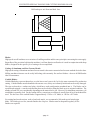
Standard Machine—The standard model has been completely assembled. Fences are set at the centerline of the
blade (see Diagram “D“ on Page No. 4). Adjust fences forward if necessary for your particular material. The
machine base must be level. The incoming material and outgoing material must lay flat on the machine base (see
Diagram “F“ on Page No. 8).
Assembly of Tables to Floor Stand:
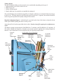
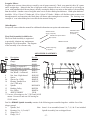
1. Assemble leg to support table with 3/8-16 bolts and nuts provided. Turn table upside down and attach leg to
tablewith leg rising vertically. Note: The hole in the table (when mounted properly) should be toward the
back of the table and far away from the blade to attach Fence Support Angle, P/N BF16 (see Diagram “A“).
2. Attach Table, P/N BF17 to machine floor stand on Angle Bracket, P/N BF05C. Use 3/8-16 bolts and nuts
provided on angle bracket.
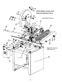
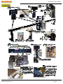
Diagram “A”
-3-