1
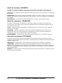
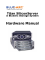
Titan SiliconServer
A BlueArc Storage System
Hardware Manual
Publication Title: Titan SiliconServer Hardware Manual
Publication Number: SX530093-05
Publication Date: March 2005
Neither BlueArc® Corporation nor its affiliated companies (collectively, “BlueArc”) makes any
warranties about the information in this manual. Under no circumstances shall BlueArc be liable for any
costs arising from the procurement of substitute products or services, lost profits, lost savings, loss of
information or data, or from any other special, indirect, consequential or incidental damages, that are
the result of its products not being used in accordance with the manual.
The product described in this manual may be protected by one or more U.S. patents, foreign patents, or
pending applications.
Microsoft®, Microsoft DOS®, Microsoft Windows®, Microsoft Windows NT®, Microsoft Windows 2000®
and Microsoft Windows 2003® are either registered trademarks or trademarks of Microsoft Corporation
in the United States and/or other countries.
All other trademarks appearing in this document are the property of their respective owners.
Copyright © March 2005 BlueArc Corporation. All rights reserved.
TITAN SILICONSERVER HARDWARE MANUAL
iii
iv
TITAN SILICONSERVER HARDWARE MANUAL
A BlueArc Storage System - - - - - - About This Manual - - - - - - - - - Other Useful Publications - - - - - - Safety Information - - - - - - - - - Electrostatic Discharge Precautions - Safety and Handling Precautions - - Electrical Precautions - - - - - - - Data Security - - - - - - - - - - - Mandatory Regulations - - - - - - - International Standards - - - - - - System Cabinet and Components - - - The Components in the System Cabinet
Titan SiliconServer - - - - - - - - - Introducing the Titan SiliconServer - Ventilation - - - - - - - - - - - - Front View - - - - - - - - - - - - Rear Panel - - - - - - - - - - - - NIM 1040-x - - - - - - - - - - - FSA 2010-x - - - - - - - - - - - FSB 301x-x - - - - - - - - - - - SIM 404x-x - - - - - - - - - - - Power Supply Unit (PSU) 600 - - - Power - - - - - - - - - - - - - Battery - - - - - - - - - - - - - PSU and Battery Care - - - - - - Powering Off the Server - - - - - Replacing Server Components - - - - Replacing a Server Module - - - - Replacing a Server PSU - - - - - - Replacing a Fan Tray - - - - - - - Powering On the Titan Storage System Powering Off the Titan Storage System -
-
-
-
-
-
-
-
-
-
-
-
-
-
-
-
-
-
-
TITAN SILICONSERVER HARDWARE MANUAL
-
-
-
-
-
-
-
-i
1
4
5
5
5
6
7
8
8
11
11
17
17
17
18
19
20
21
21
22
23
23
23
23
24
25
25
26
27
28
28
v
vi
TITAN SILICONSERVER HARDWARE MANUAL
About This Manual
This manual provides an overview of the Titan SiliconServer hardware and explains how to replace
faulty components.
For assistance with the FC-14, FC-16, SA-14, AT-14, or AT-42 storage enclosures, refer to the
corresponding User Manual on the Documentation CD ROM.
This manual is designed for administrators who are responsible for the network storage in an
organization.
The following types of messages are used throughout this manual. BlueArc recommends that these
icons and messages are read and clearly understood before proceeding:
Note:
A note contains information that helps you to install or operate the system
effectively.
CAUTION: A caution indicates the possibility of damage to data or equipment. You are
advised not to proceed beyond a caution message until you fully understand the
requirements.
WARNING: A warning contains instructions that you must follow to avoid personal injury.
Før du starter (DANSK)
Følgende ikoner anvendes i hele guiden til at anføre sikkerhedsrisici. Det anbefales, at du læser og
sætter dig ind i, og har forstået alle procedurer, der er markeret med disse ikoner, inden du fortsætter.
Bemærk: “Bemærk” indikerer informationer, som skal bemærkes.
FORSIGTIG: “Forsigtig” angiver en mulig risiko for beskadigelse af data eller udstyr. Det anbefales, at
du ikke fortsætter længere end det afsnit, der er mærket med dette ord, før du helt har sat dig ind i og
forstået proceduren.
ADVARSEL: “Advarsel” angiver en mulig risiko for den personlige sikkerhed.
Vorbereitung (DEUTSCH)
Die folgenden Symbole werden in diesem Handbuch zur Anzeige von Sicherheitshinweisen verwendet.
Lesen Sie die so gekennzeichneten Informationen durch, um die erforderlichen Maßnahmen zu
ergreifen.
Anmerkung: Mit einer Anmerkung wird auf Informationen verwiesen, die Sie beachten sollten.
VORSICHT: Das Wort “Vorsicht” weist auf mögliche Schäden für Daten oder Ihre Ausrüstung hin. Sie
sollten erst dann fortfahren, wenn Sie die durch dieses Wort gekennzeichneten Informationen gelesen
und verstanden haben.
WARNUNG: Mit einer Warnung wird auf mögliche Gefahren für Ihre persönliche Sicherheit verwiesen.
TITAN SILICONSERVER HARDWARE MANUAL
1
Antes de comenzar (ESPAÑOL)
Los siguientes iconos se utilizan a lo largo de la guía con fines de seguridad. Se le aconseja leer, y
entender en su totalidad, cualquier procedimiento marcado con estos iconos antes de proceder.
Sugerencia: Una sugerencia indica información adicional que puede serle de utilidad en la finalización
de una tarea.
PRECAUCIÓN: Una precaución indica la posibilidad de daños a los datos o equipo. Se le aconseja no
continuar más allá de una sección marcada con este mensaje, a menos que entienda el procedimiento
por completo.
ADVERTENCIA: Una advertencia indica la posibilidad de un riesgo a la seguridad personal.
Avant de commencer (FRANÇAIS)
Les icônes ci-dessous sont utilisées dans le manuel pour mettre en évidence des procédures de
sécurité. Nous vous invitons à les lire et à bien comprendre toutes les procédures signalées par ces
icônes avant de poursuivre.
Conseil : “Conseil” signale les informations complémentaires que vous pouvez trouver utiles pour
mener à bien une tâche.
ATTENTION : “Attention” signale qu’il existe une possibilité d’endommager des données ou de
l’équipement. Nous vous recommandons de ne pas poursuivre après une section comportant ce
message avant que vous ayez pleinement assimilé la procédure.
AVERTISSEMENT : “Avertissement” signale une menace potentielle pour la sécurité personnelle.
Operazioni preliminari (ITALIANO)
Le seguenti icone vengono utilizzate nella guida a scopo cautelativo. Prima di procedere Vi viene
richiesta un’attenta lettura di tutte le procedure, contrassegnate dalle suddette icone, affinché vengano
applicate correttamente.
Suggerimento: “Suggerimento” fornisce indicazioni supplementari, comunque utili allo scopo.
ATTENZIONE: “Attenzione” indica il potenziale danneggiamento dei dati o delle attrezzature in
dotazione. Vi raccomandiamo di non procedere con le operazioni, prima di aver ben letto e compreso la
sezione contrassegnata da questo messaggio, onde evitare di compromettere il corretto svolgimento
dell’operazione stessa.
PERICOLO: “Pericolo” indica l'eventuale pericolo di danno provocato alle persone, mettendo a rischio
la vostra incolumità personale.
2
TITAN SILICONSERVER HARDWARE MANUAL
Vóór u aan de slag gaat (NEDERLANDS)
De volgende pictogrammen worden in de hele handleiding gebruikt in het belang van de veiligheid. We
raden u aan alle procedure-informatie die door deze pictogrammen wordt gemarkeerd, aandachtig te
lezen en ervoor te zorgen dat u de betreffende procedure goed begrijpt vóór u verder gaat.
VOORZICHTIG: “Voorzichtig” geeft aan dat er risico op schade aan data of apparatuur bestaat. We
raden u aan even halt te houden bij de sectie die door dit woord wordt gemarkeerd, tot u de procedure
volledig begrijpt.
WAARSCHUWING: Een waarschuwing wijst op een mogelijk gevaar voor de persoonlijke veiligheid.
Antes de começar (PORTUGUÊS)
Os ícones mostrados abaixo são utilizados ao longo do manual para assinalar assuntos relacionados
como a segurança. Deverá ler e entender claramente todos os procedimentos marcados com estes
ícones ande de prosseguir.
Sugestão: Uma sugestão assinala informações adicionais que lhe poderão ser úteis para executar uma
tarefa.
CUIDADO: “Cuidado” indica que existe a possibilidade de serem causados danos aos dados ou ao
equipamento. Não deverá avançar para lá de uma secção marcada por esta mensagem sem ter
primeiro entendido totalmente o procedimento.
AVISO: Um aviso indica que existe um possível risco para a segurança pessoal.
Ennen kuin aloitat (SUOMI)
Seuraavilla kuvakkeilla kiinnitetään tässä oppaassa huomiota turvallisuusseikkoihin. Näillä kuvakkeilla
merkityt menettelytavat tulee lukea ja ymmärtää ennen jatkamista.
Huomautus: Huomautus sisältää tietoja, jotka tulee ottaa huomioon.
VAROITUS: Varoitus varoittaa tietojen tai laitteiden vahingoittumisen mahdollisuudesta. Tällä merkillä
merkitystä kohdasta ei tule jatkaa eteenpäin ennen kuin täysin ymmärtää kuvatun menettelyn.
VAARA: Vaara varoittaa henkilövahingon mahdollisuudesta.
Innan du startar (SVENSKA)
Följande ikoner används i hela handboken för att markera säkerhetsaspekter. Läs igenom handboken
ordentligt så att du förstår steg som har markerats med dessa ikoner innan du fortsätter.
Obs: “Obs” anger vad du ska observera.
FÖRSIKT: “Försikt” anger vad som kan leda till data eller utrustningsskador. Fortsätt inte till nästa
avsnitt innan du förstår det steg som har markerats med detta meddelande.
VARNING: “Varning” anger vad som kan leda till personskador.
TITAN SILICONSERVER HARDWARE MANUAL
3
Other Useful Publications
Other publications (in PDF format) available on the System Management Unit (SMU) are:
Titan SiliconServer System Administration Manual. This manual provides a full specification of the
system and instructions on how to administer the server with the Web Manager.
The documents which are listed below provide a full specification on how to configure and administer
the storage enclosures in the Titan Subsystem.
•
FC-14 User Manual.
•
SA-14 User Manual.
•
FC-16 User Manual.
•
AT-14 User Manual.
•
AT-42 User Manual.
Command Line Interface Reference. This guide (in HTML format) describes how to administer the
system by typing commands at a command prompt.
4
TITAN SILICONSERVER HARDWARE MANUAL
Safety Information
Electrostatic Discharge Precautions
To ensure proper handling of the server components and to prevent hardware faults caused by
electrostatic discharge, follow all safety precautions:
•
Wear an anti-static wrist or ankle strap.
•
Observe all standard electrostatic discharge precautions when handling plug-in modules or
components that have been removed from any anti-static packaging.
•
Avoid contact with backplane components and module connectors.
Safety and Handling Precautions
To ensure safe handling and correct operation of the equipment, follow all the safety precautions and
instructions:
•
Observe safe lifting practices. Each Titan SiliconServer or each storage array can weigh 66 lbs.
(30 kg) or more. It is important that at least two people are required to handle and position
them.
•
A Storage Cabinet must be loaded correctly to prevent any serious injuries.
1.
Place the Fibre Channel switches in the center of the storage cabinet. The recommended
rack unit positions are 23 and 24. The positions can be adjusted according to a specific
storage cabinet configuration.
2.
Load and position the Titan SiliconServer(s) directly above the Fibre Channel switches.
3.
The System Management Unit (SMU) should be placed directly below the Fibre Channel
switches.
4.
The first FC-14, FC-16, SA-14, or AT-14 enclosure should be positioned directly below the
SMU. Then continue to fill enclosures towards the bottom of the system cabinet.
5.
With an AT-42 enclosure, it must be placed at the bottom of the storage cabinet. A
maximum of five AT-42s can be fit on the bottom of the system cabinet if it is filled from the
bottom up. For stability and accessibility reasons, an AT-42 must not be placed on the tophalf (21U) of the storage cabinet.
6.
Once the bottom half of the storage cabinet has been filled, the top half of the storage
cabinet can be filled. Begin by placing a storage component directly above the Titan
SiliconServer and fill upwards.
Note:
7.
All expansion cabinets including all storage enclosures, must be filled from the
bottom to the top.
To access the disks in an AT-42 enclosure, slide the unit forward on its rails.
WARNING: There is a risk that the cabinet could fall over suddenly. To prevent this from
occurring:
• Do not remove the AT-42 past the line on the top of the unit.
• Do not remove more than one unit at a time.
•
BlueArc recommends that the stabilizer plate be secured to the front of the system cabinet.
Refer to Attaching the Stabilizer Plate section.
TITAN SILICONSERVER HARDWARE MANUAL
5
Electrical Precautions
6
•
Provide a suitable power source with electrical overload protection to meet the requirements
outlined in the technical specification.
•
Provide a power cord suitable for the country of installation if a power cord is not supplied.
•
Provide a safe electrical ground connection to the power cord (check the grounding of an
enclosure before applying power).
•
Disconnect all supply power for complete isolation if power is supplied from multiple AC
sources.
•
Only operate the Titan Storage System from nominal mains input voltages of 110VAC 60 Hz,
208VAC 60Hz or 240VAC 50 Hz (CE rating).
•
Unplug a system component if it needs to be moved or if it is damaged.
TITAN SILICONSERVER HARDWARE MANUAL
Data Security
•
Each storage enclosure contains multiple removable Hard Disk Drive (HDD) modules. These
units are fragile. Handle them with care and keep them away from strong magnetic fields.
•
All supplied plug-in modules and blanking plates must be in place to complete the internal
circuitry and enable air to flow correctly around an enclosure.
•
Using the system for more than a few minutes with modules or blanking plates missing can
cause an enclosure to overheat, leading to power failure and data loss. Such use may invalidate
the warranty.
•
A loss of data may occur if a hard drive module is removed. Immediately replace any modules
that are removed. If a module is faulty, replace it with one of the same type, of at least the
same capacity and speed.
•
Always shut down a server before it is moved, switched OFF, or reset.
•
Maintain backup routines.
•
FC-14 and SA-14 storage enclosures are fitted with optical SFP transceivers manufactured by
JDS Uniphase. Other storage enclosures (FC-16, AT-14 and AT-42) are fitted with SFPs
manufactured by Finisar or Infineon. To ensure proper operation of the Titan Storage System,
BlueArc recommends that the JDS SFPs are only used in FC-14 storage enclosures and Finisar
or Infineon SFPs are used in all the other storage enclosures (FC-16, AT-14, AT-42).
•
Do not abandon backup routines. No system is completely foolproof.
TITAN SILICONSERVER HARDWARE MANUAL
7
Mandatory Regulations
The sections that follow outline the mandatory regulations governing the installation and operation of
the system. Adhere to these instructions to ensure that regulatory compliance requirements are met.
International Standards
The equipment described in this manual complies with the requirements of the following agencies and
standards:
•
CSA 60950-00/UL 60950; EN 60950
•
FCC Part 15 Class A; EN 55022 Class A; EN 55024
Federal Communications Commission (FCC)
This equipment has been tested and found to comply with the limits for a Class A digital device,
pursuant to Part 15 of the FCC Rules. These limits are designed to provide reasonable protection
against harmful interference when the equipment is operated in a commercial environment. This
equipment generates, uses, and can radiate radio frequency energy and, if it is not installed and used in
accordance with the instruction manual, may cause harmful interference to radio communications.
Operation of this equipment in a residential area is likely to cause harmful interference, in which case
the users will be required to correct the interference at their own expense.
Properly shielded and grounded cables and connectors must be used in order to meet FCC emission
limits. Neither the provider nor the manufacturer is responsible for any radio or television interference
caused by using non-recommended cables and connectors, or by unauthorized changes or
modifications to this equipment.
Unauthorized changes or modifications could void the user's authority to operate the equipment.
This device complies with Part 15 of the FCC Rules. Operation is subject to the following two conditions:
1.
The device may not cause harmful interference.
2. The device must accept any interference received, including interference that may cause undesired
operation.
European Union (EU) Statement
This product conforms to the protection requirements of the following EU Council Directives:
•
89/336/EEC Electromagnetic Compatibility Directive
•
73/23/EEC Low Voltage Directive
•
93/68/EEC CE Marking Directive
The manufacturer cannot accept responsibility for any failure to satisfy the protection requirements
resulting from a non-recommended modification of the product.
This product has been tested and found to comply with the limits for Class A Information Technology
Equipment according to European Standard EN 55022. The limits for Class A equipment were derived
for commercial and industrial environments to provide reasonable protection against interference with
licensed communication equipment.
8
TITAN SILICONSERVER HARDWARE MANUAL
CAUTION: This is a Class A product and as such, in a domestic environment, may cause radio
interference.
Canadian Department of Communication Compliance Statement
This Class A digital apparatus meets all the requirements of the Canadian Interference-Causing
Equipment Regulations.
Avis de conformité aux normes du ministère des Communications du
Canada
Cet appareil numérique de la classe A respecte toutes les exigences du Règlement sur le matériel
brouilleur du Canada.
Radio Protection for Germany
Dieses Gerät erfüllt die Bedingungen der EN 55022 Klasse A.
Food and Drug Administration (FDA)
The product complies with FDA 21 CFR 1040.10 and 1040.11 regulations, which govern the safe use of
lasers.
TITAN SILICONSERVER HARDWARE MANUAL
9
10
TITAN SILICONSERVER HARDWARE MANUAL
System Cabinet and Components
The Components in the System Cabinet
The system is housed in a 42U or 25U high cabinet. A U is a unit of measurement equivalent to 1.75
inches or 44.1 millimeters. The main components are:
•
Titan Storage Server
The system may contain a single server, or two servers that operate as a cluster pair. For
instructions on how to implement a cluster configuration, refer to the System Administration
Manual.
Titan Front View
Titan Rear View
TITAN SILICONSERVER HARDWARE MANUAL
11
•
Storage Subsystem
A storage cabinet containing the Titan SiliconServer can hold a maximum of nine storage
enclosures. A maximum of 13 storage enclosures can be placed in an expansion cabinet. Titan
supports the following storage enclosures:
Storage
Tier
Supported
Enclosures
Storage
Technology
Disk
RPM
RAID
Technology
Performance
Characteristics
Tier 1
FC-14,
FC-16
Dual ported
FC disks
15,000
RAID 5;
RAID 1/5/10
Very high
performance
Tier 2
FC-14,
FC-16
Dual ported
FC disks
10,000
RAID 5;
RAID 1/5/10
High
performance
Tier 3
SA-14,
AT-14
SATA disks
PATA disk
7,200
RAID 5
Nearline
performance
Tier 4
AT-14,
AT-42
PATA disks
5,400
RAID 5
Archival
Tier 5
N/A
Tape
NA
N/A
Long term
storage
The subsystem can support Fibre Channel and ATA disk subsystems which comprise of:
º
FC-16: A storage enclosure containing 16 Fibre Channel disk drives. In the subsystem,
one storage enclosure serves as the main enclosure (storage controller) and contains dual
RAID controllers. Each RAID controller has two RAID host ports and a single expansion
port. The RAID controller host ports connect to the Fibre Channel switches, while the
expansion port can be used to connect to Loop Resiliency Circuit (LRC) modules in other
enclosures, which serve as expansion enclosures. Expansion enclosures are fitted with dual
LRC modules. A RAID controller pair can support an array of up to 64 drives.
FC-16
12
TITAN SILICONSERVER HARDWARE MANUAL
º
FC-14: A storage enclosure containing 14 Fibre Channel disk drives. In the subsystem,
one storage enclosure serves as the Storage Controller Enclosure (SCE) and contains dual
RAID controllers. Each RAID controller has two RAID host ports and a single cascade port.
The cascade port is used to connect to the Environmental Services Monitoring (ESM)
modules in the Storage Expansion Enclosure (SEE). The SEE consists of a storage enclosure
fitted with dual ESM modules. Each ESM module has two interfaces on it that are used to
Loop In and Loop Out of the SEE. A RAID controller pair supports an array of up to 112
drives.
FC-14
º
SA-14: A storage enclosure containing 14 SATA disk drives. The SA-14 is distinguishable
from the FC-14 by the gray locking handle on the bottom of the drive carrier. In the
subsystem, one storage enclosure serves as the SCE and contains dual RAID controllers.
Each RAID controller has two RAID host ports and a single cascade port. The cascade port
is used to connect to the ESM modules in the SEE. The SEE consists of a storage enclosure
fitted with dual ESM modules. Each ESM module has two interfaces on it that are used to
Loop In and Loop Out of the SEE. A RAID controller pair supports an array of up to 112
drives.
SA-14
TITAN SILICONSERVER HARDWARE MANUAL
13
º
AT-14: A storage enclosure containing 14 PATA disk drives. AT-14 storage enclosures
contain a single RAID controller with two RAID host ports. The RAID controller host ports
connect to the Fibre Channel switches.
AT-14
º
AT-42: A storage enclosure containing up to 42 PATA disk drives. AT-42 storage
enclosures contain a single RAID controller with two RAID host ports. The RAID controller
host ports connect to the Fibre Channel switches.
AT-42
•
Fibre Channel switches
BlueArc supports Fibre Channel switches which connect multiple servers and storage
subsystems. The qualified Fibre Channel switches are:
•
Brocade SilkWorm 3250/3850
•
Brocade SilkWorm 4100
•
Vixel 9000 series: Vixel 9100 and Vixel 9200
•
Vixel 355
Note:
14
For additional data protection, it is recommended to use an external UPS to power the
Titan Storage System.
TITAN SILICONSERVER HARDWARE MANUAL
Attaching the Stabilizer Plate
The stabilizer plate and mounting hardware are supplied with the 19-inch rack.
1.
To attach the stabilizer plate to the front of the system cabinet, place the stabilizer plate up against
the cabinet.
2.
Align the holes from the stabilizer plate to the holes on the bottom of the cabinet.
3.
Place the screws in the hole and secure them into the cabinet.
4.
The stabilizer contains two holes for securing it to the ground. Suitable screws must be used to
secure the stabilizer.
TITAN SILICONSERVER HARDWARE MANUAL
15
16
TITAN SILICONSERVER HARDWARE MANUAL
Titan SiliconServer
Introducing the Titan SiliconServer
The server chassis is 4U (7”) high, 480 millimeters (19”) rack mountable and a maximum of 600
millimeters (22”) deep excluding the fascia. The server chassis consists of a passive backplane (which is
not removable), three hot swappable fan trays, and dual power supplies.
The pre-installed components perform functions essential to the integrity of the server. If there is an
issue with these components, replace them with the same component type. For more information, refer
to the Replacing Server Components section.
CAUTION: Each server power supply contains a lithium-ion battery that can only be serviced
by a BlueArc service engineer. The replacement battery must be of the same or
equivalent type recommended by the manufacturer. Dispose of any used batteries
in accordance with the manufacturer’s instructions.
Ventilation
On a Titan SiliconServer, there are vents and fan openings on the front and the rear. These openings
are designed to prevent the server from overheating.
Therefore, at least four inches of clearance must be present at the rear of the server rack so that
airflow is unrestricted.
CAUTION: Do not place the server in a built-in installation unless proper ventilation is
provided.
Do not operate the server in a cabinet whose internal ambient temperature
exceeds 40º C (104º F).
TITAN SILICONSERVER HARDWARE MANUAL
17
Front View
Status Power LED
Server Status LED
On the front panel there are two LED indicators (Power and Status), which indicate the server status as
follows:
Table 1: Status Power LED (Green)
State
Meaning
Green
Normal operation with a single server or an active server in a clustered operation.
Slow Flash
Server has been shutdown. Flashes once every three seconds.
Flash (0.8Hz)
Server is available to host file services but is not currently doing so.
Flash (5Hz)
Server rebooting.
Off
Server not powered up.
Table 2: Server Status LED (Amber)
State
Meaning
Amber
Critical failure and server is not operational .
Slow Flash
Server shutdown has failed. Flashes once every three seconds.
Flash
(0.8Hz)
Server needs attention, and a non-critical failure has been detected. For example, a
fan or power supply has failed.
Off
Normal operation.
18
TITAN SILICONSERVER HARDWARE MANUAL
Rear Panel
There are a number of LED indicators on the modules and PSUs. Each module has a Status LED (Green/
Amber).
Table 3: Module Status LED (Green/Amber)
State
Meaning
Green
Normal Operation
Flash Green (5Hz)
Module is booting and running self test
Amber
Critical fault with the module hardware
Flash Amber (5Hz)
Module is about to reset system due to manual reset or fault condition
Off
No power
TITAN SILICONSERVER HARDWARE MANUAL
19
Additionally each module has individual indicators as shown below:
NIM 1040-x
Table 4: Server Gigabit Ethernet Ports (4)
State
Meaning
Per Port Status (Green)
Green
1,000 Mbps link present
Flash (1.25Hz)
1,000 Mbps link standby in a redundant configuration
Off
No link
Per Port Activity (Amber)
Amber Flash
Network activity
Off
No Network activity
Table 5: 10/100 Ethernet Management Ports (4)
State
Meaning
Per Port Status (Green)
Green
10 or 100 Mbps link present
Off
No link
Per Port Activity (Amber)
Amber Flash
Network activity
Off
No network activity
The NIM 1040-x module also has 2 LED indicators which indicate the current server status. These LEDs
are a mirror of the LEDs on the front panel, refer to the Front View section.
20
TITAN SILICONSERVER HARDWARE MANUAL
FSA 2010-x
The FSA module has only one LED which is the Module Status LED.
Table 6: FSA Module Status LED
State
Meaning
Green
Normal operation.
Flash Green (5 Hz)
Board is booting, running self-test or resetting.
Amber
Critical fault with the module (hardware).
Off
No power.
FSB 301x-x
The FSB module has only one LED which is the Transaction Log Status LED (Green/Amber). This LED
indicates the status of a battery backed NVRAM.
Table 7: Transaction Log Status LED (Green/Amber)
State
Meaning
Off
Transaction logging disabled, or battery exhausted.
Green
Transaction log active (locally or with remote server).
Amber
Battery condition fault.
Green Flash
(1Hz)
Recoverable transaction log held in NVRAM.
Amber Flash
(1Hz)
There is a recoverable transaction log in NVRAM (as per green flash) and the
battery is low.
TITAN SILICONSERVER HARDWARE MANUAL
21
SIM 404x-x
Table 8: Fibre Channel Ports
State
Meaning
Per Port Status (Green)
Green
1 or 2 Gbps FC link present
Off
No link
Per Port Activity (Amber)
Amber Flash
Network activity
Off
No network activity
Table 9: High Speed Interface (HSI)
State
Meaning
Per Port Status (Green)
Green
Link present
Off
No link
Per Port Activity (Amber)
Amber Flash
Network activity
Off
No network activity
22
TITAN SILICONSERVER HARDWARE MANUAL
Power Supply Unit (PSU) 600
Table 10: PSU Status (Green/Amber)
Status
Meaning
Green
Mains, DC, and battery are okay
Amber
PSU Failure (including internal fans or battery)
Off
No mains connections or switched off
Power
The Titan SiliconServer monitors the operational status of the power supply modules
so that the management interfaces can indicate the physical location of the failed
unit. However, it is not possible to distinguish between failed components within a
PSU module (such as built in fans).
Titan has dual, hot-swappable, load sharing, AC power supplies. The power supplies
are serviced and accessible from the rear of the Titan SiliconServer.
Mains power connections are an IEC inlet in each power supply. Each PSU is only
powered from its mains inlet. Two power feeds are required for the system. Each PSU
has an on/off switch to turn on and off the unit without removing the power cabling.
The power connections also have a retaining clip which prevents accidental removal
of the cable.
Each power supply auto-ranges over an input range of 90V to 240V AC, 50Hz to 60Hz.
Battery
Each power supply includes a battery unit that is part of Titan’s stable storage solution. The batteries
within each PSU module operate in both a redundant and parallel manner.
Both batteries must be present and charged to support the full NVRAM backup period, but either
battery on its own can backup the NVRAM for a shorter period of time. A fully-charged, dual battery
system should keep the server’s NVRAM alive for about 72 hours. Charging time will be at a rate of 8
hours of backup for every hour of charging time, or approximately nine hours for a complete charge.
PSU and Battery Care
Each PSU contains a battery used for NVRAM. To maximize the performance of the battery, it is
necessary to fully charge the battery.
Complete battery discharge can happen if the server is not shutdown correctly, in which case the
NVRAM LED will indicate that the NVRAM is still powered. Verify that the server has been shutdown
correctly before powering off. If a proper shutdown was not possible and NVRAM does not need to be
preserved, then removal of both PSU modules at the same time, for a few seconds, will ensure that the
NVRAM enters the OFF state and the batteries no longer supply power to the NVRAM.
When preparing a Titan SiliconServer for shipment or if it is powered down for any length of time, it is
important that the server has been shutdown correctly before powering-off. Otherwise, if the server is
improperly shutdown, the batteries supplying the NVRAM will become fully discharged. This also occurs
if the server is powered down for too long without following the proper procedure.
TITAN SILICONSERVER HARDWARE MANUAL
23
Powering Off the Server
To reset or shutdown the Server
The server can be reset or shutdown if a manual reboot is necessary.
Using the SMU, select Reset/Shutdown from the SiliconServer Admin page.
The Reset/Shutdown page has two options to power-off the server:
•
The Reset button will close down all processes on the server and all connections from other
hosts. It will restart the server automatically which may take approximately five minutes.
Check the Both box to reset both cluster nodes if configured as a cluster.
•
The Shutdown button will shutdown everything running on the SMU server, close all
connections, and bring the SMU server to a state in which it may be safely powered down.
Check the Both box to shutdown both cluster nodes if configured as a cluster.
To power down the Server for Shipment
1.
From the console, run the command shutdown –-ship.
2.
Wait for the console to output the message Information: Server has shut down.
3.
Power down the Titan server by switching off both PSU modules.
4.
Check that the NVRAM status LED on the FSB module is off.
The server is now fully shutdown.
5.
If the NVRAM status LED is On (either green or amber), then remove both PSU modules
simultaneously for at least 10 seconds and replace.
6.
If the Titan server fails to shutdown properly or to verify that the NVRAM has not entered the
battery powered back-up state when the PSUs are switched off, remove both PSU modules.
However, this procedure should be followed whenever a Titan SiliconServer is to be powered down and
will be left off more than a day. For instance, this is not necessary if the system is power-cycled.
Complete battery discharge can also happen if the server is shutdown correctly but left in an
unpowered state for more than 20 days, with the PSU modules plugged in. If the server is to be left
powered off for any significant period of time, it is recommended that the PSU modules are removed
from the chassis.
For long term storage of PSU spares, please contact BlueArc Global Services.
24
TITAN SILICONSERVER HARDWARE MANUAL
Replacing Server Components
This section describes how to replace the hot-swappable components in the server. Follow the
procedure if you are a qualified System Administrator, Network Administrator, or Technician.
Replacing a Server Module
CAUTION: All power to the server must be switched off before replacing any modules.
1.
Verify that the power switches on both the PSU’s are in the OFF position.
2.
Unscrew the Retaining Screws (the screw is only a 1/4 turn) of the module. The Retaining Screws
are spring-loaded and remain in the module.
Ejection Lever
Retaining Screws
Module Position
3.
Remove the module by pulling and lifting the Ejection Levers outwards.
4.
Slide the module carefully out of the enclosure.
5.
Replace the module by sliding the new module in the correct position (refer to the module position
indicator) until it stops.
Note:
Modules are ‘keyed’ only to fit into their correct slot. Therefore, do not try and force
a module into a different slot. The module position in the chassis is indicated by the
graphic in the bottom right hand corner of each module.
6.
Lock the module in place by pushing inwards on the Ejection Levers until a click is heard.
7.
Re-fasten the Retaining Screws.
8.
Switch the power switches on the PSU’s to the ON position.
TITAN SILICONSERVER HARDWARE MANUAL
25
Replacing a Server PSU
1.
Verify that the power switch on the faulty PSU is in the OFF position.
2.
Remove the power cord.
3.
Unscrew the Retaining Screw of the faulty PSU.
4.
Remove the PSU from the server.
5.
Ensure that the power switch on the replacement PSU is in the OFF position.
Power Supply
Unit 1
Power Switch
6.
Insert the replacement PSU.
7.
Replace the Retaining Screw of the PSU.
8.
Insert the power cord.
9.
Switch the power to the ON position on the replacement PSU.
26
TITAN SILICONSERVER HARDWARE MANUAL
Power Supply
Unit 2
Replacing a Fan Tray
The Titan SiliconServer fans are contained within three individual fan trays. These are located behind
the front fascia and are removable from the front of the server. The fans provide for front to back
airflow to be consistent with the storage system components. The server continues to operate following
the failure or removal of a single fan.
The Titan SiliconServer’s cooling airflow enables the server to operate in an ambient temperature range
of 10°C to 40°C when mounted in a storage cabinet with associated components required to configure
a high performance storage system. The Storage System Administrator is responsible for ensuring that
the ambient temperature within the rack does not exceed the 40°C operating limit for the Titan Server.
Release Latch
Lift up to open.
CAUTION: If a fan has failed, replace the fan tray as soon as possible to avoid damaging the
server.
To replace a Fan Tray
1.
Remove the server front panel by releasing the two latches (one each side).
2.
Grasp the center logo to remove the front panel.
The fans will then be visible:
Fan
3.
Fan
Fan
Loosen the screws at the top and bottom of the faulty fan.
TITAN SILICONSERVER HARDWARE MANUAL
27
4.
Slide the Fan Tray out of the server.
5.
Insert the replacement tray. Push firmly to seat it correctly.
6.
When the connector is firmly in place, secure the tray with the screws which were previously
removed.
7.
Replace the server’s front panel.
Powering On the Titan Storage System
1.
Check that the servers are switched off.
2.
Power on all Expansion Enclosures.
3.
Once the disk LEDs on all of the Expansion Enclosures have stopped blinking, which indicates that
they are spinning up, power on the Main Enclosures. Main Enclosures are identified as the
enclosures that house the RAID controllers.
4.
To power on the System Management Unit (SMU), depress the red button located on the right of
the unit.
5.
Switch on the Titan SiliconServer(s).
Powering Off the Titan Storage System
1.
Switch off the Titan SiliconServer(s).
2.
To turn off the System Management Unit (SMU), depress the red button located on the right of the
unit.
3.
Power off the Main Enclosures. Main Enclosures are identified as the enclosures that house the RAID
controllers.
4.
Power off the Expansion Enclosures.
28
TITAN SILICONSERVER HARDWARE MANUAL
Management Interfaces
The Titan SiliconServer offers two types of physical management ports:
•
Two RS232 Serial connections (DB-9)
•
Four switched 10BaseT/100BaseTX Ethernet ports
Two RS-232 Serial connections (DB-9)
Four
10/100BaseT
Ethernet Ports
All management ports are physically located on the NIM, and provide connections to ports within the
Titan Storage System cabinet only. The System Management Unit (SMU) in Titan provides the rack
component management function.
Serial Management Ports
The Titan SiliconServer has an RS232 connection that can be used as a management console
connection (Command Line Interface). The configuration functions can be performed from any VT100
terminal emulation interface.
Connect the terminal to port 1 on the rear of the server, then set the host settings to the values below
to ensure proper communication between the terminal and server.
Table 11: Host Setting Values
Terminal
Requirement
Connection
Crossover (nullmodem) cable
Protocol
Asynchronous RS232
Baud rate
115,200 Bps
Data bits
8
Stop bits
1
Parity
None
Flow control
None
TITAN SILICONSERVER HARDWARE MANUAL
29
The table below shows the pin layout for port 1.
Table 12: Port 1 Pin Layout
Pin Positions
30
Signal
Abbreviation
Pin
Data Carrier Detected
DCD
1
Receive Data
RD
2
Transmit Data
TD
3
Data Terminal Ready
DTR
4
Signal Ground
SG
5
Data Set Ready
DSR
6
Request To Send
RTS
7
Clear To Send
CTS
8
Ring Indicator
RI
9
TITAN SILICONSERVER HARDWARE MANUAL