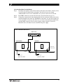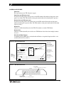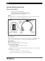
1
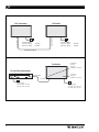
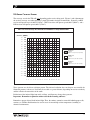
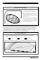
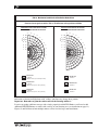
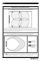
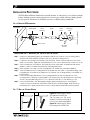
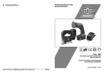
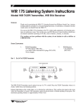
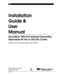
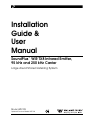
Installation
Guide &
User
Manual
SoundPlus ™ WIR TX8 Infrared Emitter,
95 kHz and 250 kHz Carrier
Large Area Infrared Listening System
Model WIR TX8
Optional Receiver Model WIR RX4
MAN 081F
SOUNDPLUS ™ WIR TX8 INFRARED EMITTER,
95 KHZ AND 250 KHZ CARRIER
INSTALLATION GUIDE AND USER MANUAL
Contents
Page
SYSTEM OVERVIEW
3
INSTALLATION PROCEDURE
5
TX8 EMITTER COVERAGE PATTERNS
TX8 EMITTER SETUP
TX8 POWER WIRING
USING MULTIPLE EMITTERS
11
CONTROLS AND FEATURE
13
TX8 REAR PANEL
TX8 BOTTOM PANEL
RECEIVER SAFETY INFORMATION
14
RECEIVER INSTRUCTIONS
15
RECEIVER MANAGEMENT
15
TROUBLESHOOTING
16
SPECIFICATIONS
17
WARRANTY
19
NOTES: TAKING A FEW MINUTES NOW TO READ THESE INSTRUCTIONS WILL SAVE TIME AND ENSURE PROPER
SYSTEM OPERATION.
INFRARED RECEIVER PERFORMANCE CAN BE DEGRADED IF THIS SYSTEM IS USED IN CLOSE PROXIMITY
TO HIGH-EFFICIENCY LIGHTING EQUIPMENT WITH SOLID STATE BALLASTS (I.E. HIGH EFFICIENCY
FLUORESCENT) THAT OPERATE AT FREQUENCIES NEAR 95 KHZ. 250 KHZ OPERATION SHOULD BE USED
WHEN THIS OCCURS.
The TX8 is a CLASS 1 LED PRODUCT
2
SYSTEM OVERVIEW
The Williams Sound WIR TX8 Infrared Emitter is designed to operate with a WIR TX10
Infrared System or modulator that sends a 95 kHz or 250 kHz frequency modulated signal to
the TX8 Emitter via coaxial cable.
The WIR TX8 emits invisible infrared light into the listening area. Infrared receivers detect
the transmission and convert the light signals back into audio signals.
The system is designed to transmit high quality audio for hearing assistance and language
interpretation applications. Because the system uses infrared light for transmission, it is not
affected by radio equipment and does not interfere with radio equipment. No FCC license is
required. The coverage area for the TX8 will vary depending on the receiver being used. (see
Figures 2 and 4 to demonstrate the receiver coverage area when operating a single TX8
emitter in single channel mode). Generally, a RX4 receiver will operate up to 4,000 ft2 (370
m2). Larger areas can be covered by connecting additional WIR TX8 Emitters.
3
FIGURE 1A: TYPICAL SYSTEM CONFIGURATIONS
TX10 Transmitter
TX8 Emitter
Baseband In
Baseband Out
Power Supply
120 VAC (US):
230 VAC (CE):
TFP 010
TFP 027
Power Supply
120 VAC (US):
230 VAC (CE):
TFP 010
TFP 027
Baseband Signal
FIGURE 1B: USING A TX8 EMITTER WITH A COMPATIBLE 95KHZ/250KHZ MODULATOR
TX8 Emitter
Baseband
Present
Indicator
(Visible From Below)
95 kHz/250 kHz Modulator
MOD 111 Selectable 95/250kHz Infrared System Modulator
3
2
1
Power
4 5 6
7
8 Audio Level
CXR
9
10
0
CH 1 Level
Williams Sound
Baseband Out
Phones
Audio
Limit
Infrared
Test Out
Compress
Power On
Indicator
(Visible From Below)
Baseband In
Power Supply
120 VAC (US): TFP 016
230 VAC (CE): TFP 027
4
Power Supply
120 VAC (US): TFP 010
230 VAC (CE): TFP 027
TX8 EMITTER COVERAGE PATTERNS
The coverage area for the TX8 will vary depending on the receiver being used. Figures 2 and 4 demonstrate
the receiver coverage area when operating a single TX8 emitter in single channel mode. Generally, an RX3
receiver will operate up to 10,000 ft2 (930 m2); a RX7/8 receiver will operate up to 6,000 ft2 (560 m2); and a
RX4 receiver will operate up to 4,000 ft2 (370 m2).
FIG 2: Receiver Coverage Area with TX8 or TX10 Emitter in Single Channel Mode
(METERS) (FEET)
27
90
24
80
21
70
18
60
15
50
12
40
9
30
6
20
3
10
0
0
-3
- 10
-6
- 20
-9
- 30
- 12
- 40
- 15
- 50
- 18
- 60
- 21
- 70
- 24
- 80
- 27
- 90
RX3 Receiver
1 Channel
(Approx. 10,000 sq. feet., 930 sq. meters)
RX7/8 Receiver
1 Channel
(Approx. 6,000 sq. feet., 560 sq. meters)
RX4 Receiver
1 Channel
(Approx. 4,000 sq. feet., 370 sq. meters)
0
0
10 20 30 40 50
3
6
9
12
15
60 70 80 90 100 110 120 130 140
18
21
24
27
30
34
37
40
43
These patterns are the direct radiation pattern. The infrared radiation does not drop to zero outside the
illustrated patterns; it decreases. It still may be useable at a greater distance, depending on receiver sensitivity
and the reflective characteristics of the room.
Reflections of the infrared light from walls, ceilings, and floors may change these patterns.
Important: Remember to point the emitter towards the listening audience!
Remember: opaque objects block infrared light. Thus, the emitters cannot be concealed behind opaque walls,
curtains, etc. Neither should emitters be used in areas of extreme high or low temperatures, humidity, or
chemical environments.
5
FIG 3a: 3-Dimension Foot Pattern
The TX8 floods the listening audience with
a cone shape light pattern as shown here.
The path of the cone shape light leaves a
pattern on the ground, or "foot print," and
indicates where the strongest receiver
reception will occur.
The actual coverage area will vary depending
on the signal strength of the receiver being
used. Refer to Figures 2 and 4 to determine
how many emitteres are required for 100%
coverage of the listening area.
To determine the best location for the emitter, it helps to think of the IR emitter as an invisible floodlight.
You’ll want to aim it so the listeners are “flooded” with the infrared light. The emitter should also be
positioned high enough so it won’t be blocked by people and other physical obstructions. See Figure 3b
below. Mount the emitter at least 2 ft. (.61 m) above the audience. Position the emitter to face in a
slightly downward angle - that will increase the “throw” of the infrared beam.
FIG 3b: Vertical Beam Spread
Minimum receiver RANGE when operating with a TX8 or TX10 emitter in Single Channel Mode.
RX3 Receiver: 120' (37 m)
RX7/8: 80' (24 m)
RX4: 70' (21 m)
(Range)
TX8
eam
f Emitter B
Center O
30'
SCREEN
6'
STAGE
6
FIG 4: Horizontal and Vertical Radiation Polar Plots
Receiver Coverage Area with a TX8 or TX10 Emitter in Single Channel Mode
HORIZONTAL RADIATION POLAR PATTERNS
DISTANCE FROM EMITTER TO RECEIVER
120
30
– 90
– 70
– 60
– 50
100
24
80
18
60
12
40
6
20
– 40
– 30
42
140
36
120
30
– 80
– 70
– 60
– 50
100
24
80
18
60
12
40
6
20
– 20
– 10
FEET
36
– 80
METERS
140
FEET
METERS
– 90
42
VERTICAL RADIATION POLAR PATTERNS
DISTANCE FROM EMITTER TO RECEIVER
– 40
– 30
– 20
– 10
0
0
10
10
20
20
30
30
40
40
50
50
60
90
80
60
70
90
80
70
RX3 Receiver
1 Channel
(Approx. 10000 sq. feet., 930 sq. meters)
RX3 Receiver
1 Channel
RX7/8 Receiver
1 Channel
(Approx. 6000 sq. feet., 560 sq. meters)
RX7/8 Receiver
1 Channel
RX4 Receiver
1 Channel
(Approx. 4000 sq. feet., 370 sq. meters)
RX4 Receiver
1 Channel
Reflections of the infrared light from walls, ceilings, and floors may change these patterns.
Important: Remember to point the emitter towards the listening audience!
If you’re not getting sufficient coverage with a single, properly installed TX8 Emitter, you’ll need to add
additional WIR TX8 Emitters to achieve full coverage of your listening area (see instructions on page 11).
Figures 5a and 5b illustrate how multiple emitters can be used for large room installations.
7
Multiple Emitters Installed to Maximize Coverage
FIG. 5a: Overlapping Illumination Patterms to Cover Larger Listening Areas
TX10
TX8
TX8
TX8
Fig. 5a above is a typical example of how multiple emitters are used to cover larger listening areas.
Generally, it is desirable for the illumination patterns to overlap. Note: The coverage area will vary
depending on the infrared receiver being used; refer to Figures 2 and 4 to determine how many emitters
are required to achieve full coverage of a listening area.
FIG. 5b: Using Two Emitters at Same Emission Point to Increase Coverage Area
Coverage area
with Single Emitter
TX10
TX8
Coverage area
with Second Emitter
Added to Same
Emission Point
(50% increase)
When two emitters are used at the same emmission point in single channel mode, the overall coverage area
increases 50%. When using an RX3 receiver, as a result, the coverage area will increase to 15,000 ft2 (1,393
m2); the RX7/8 will increase to 9,000 ft2 (836 m2); and the RX4 will increase to 6,000 ft2 (557 m2).
8
INSTALLATION PROCEDURE
The TX8 Infrared Emitter should not be installed outdoors, or where there is a lot of direct sunlight
indoors. Sunlight generates infrared interference. Certain types of high-efficiency lighting fixtures
can also generate interference at 95 kHz because they use high frequency modulation.
FIG. 6: BRACKET 024 MOUNTING
TX8 Emitter
Swivel Head
Shaft
(optional)
Shaft
Plate
Cover
Mounting
Plate
(To Wall or Ceiling)
tension screw
Mounting
Screws
INSTALLATION STEP 1: MOUNTING THE TX8 TO A WALL OR CEILING
Step 1: Using the mounting plate (Figure 6) as a template, mark the hole locations on the mounting surface
where the TX8 will be installed. See Figure 7 below for optional mounting positions.
Step 2: Locate the top mounting hole in the rear of the TX8 emitter. Gently screw the male end of the swivel
head on to the emitter. Tighten the swivel head tension screw: turn clockwise until the connection is secure.
Step 3: Screw the male end of the shaft into the female end of the swivel head. An additional shaft can be
added to create more distance between the wall/ceiling and Emitter.
Step 4: Place the plate cover snugly over the mounting plate. This will hide the screws after installation.
Step 5: Screw the male end of the mounting plate into the female end of the shaft. For suspended ceilings, screw
the female end of the shaft into the male end of the T-Bar clip. The mounting bracket is now installed on to
the TX8 Emitter.
Step 6: Position the TX8 Emitter and BKT 024 so the mounting plate lines up with the marked holes on the
mounting surface. Fasten the mounting plate to the surface using screws and wall anchors. Mounting
the TX8 to a Suspended Ceiling with Cross Tee: Fasten the T-Bar clip on to the desired Cross Tee.
Step 7: Position the TX8 Emitter to the desired angle: Begin by gently turning the tension screw (Figure 6)
counter clockwise to release the swivel head. Adjust the TX8 to the desired angle. When the TX8 is in
the desired position, gently turn the tension screw clockwise until the swivel head is securely in place.
FIG. 7: WALL OR CEILING MOUNT
a
b
Figure 7a: Mounting the TX8 on
to a wall with the BKT 024.
Tip: To keep the TX8 level,
rotate the tension screw (Fig. 6)
so it rests on top of the bracket.
Figure 7b: Mounting the TX8 on
to a ceiling with the BKT 024.
9
POWER WIRING
FOR U.S. APPLICATIONS:
The TX8 Emitter is supplied with a low-voltage wall transformer power supply (TFP 010). Twoconductor 18 ga. power cord is included with the emitter.
POWER CONNECTIONS FOR APPLICATIONS OUTSIDE THE U.S. REQUIRING 240 VAC MAINS SUPPLY:
WIR TX8
Use an appropriate power adaptor supplied by the local distributor which meets the following
Secondary Specifications: 24 VAC, 30 VA, 50/60 Hz
!! IMPORTANT WARNING !!
SHORTING THE POWER SUPPLY OUTPUT TERMINALS WILL BLOW A NON-REPLACEABLE
INTERNAL FUSE, DESTROYING THE POWER SUPPLY UNIT!
POWERLINE VOLTAGE MUST NOT FALL BELOW 94V, OR SYSTEM PERFORMANCE WILL BE
GREATLY REDUCED!
DO NOT CONNECT THE POWER SUPPLY TO AC POWER YET!!!
Step 1:
Determine the length of power cord needed to reach from the emitter to the AC wall
outlet where the power supply will be plugged in. Power cord length must not exceed
200 feet (61 m). If the distance exceeds 200 feet, heavier gauge wire is required. Make
sure the power supply is not plugged into AC power yet!
One end of the power cord has a 3-pin Molex connector, the other end is bare. Cut the
bare end of the power cord to length. Strip this end down the middle approximately 1
inch, then strip both of the resulting strands about 1/8 inch. Install the crimp-on spade
terminals supplied and connect these to the screw terminals on the TFP 010 Power
Supply. Polarity is not important since AC power is being used.
Step 2:
Plug the 3-pin connector into the TX8’s Power In connector.
Step 3:
Plug in the TFP 010 Power Supply last.
The Power Indicator LED in the lower right of the front panel glows when the TX8 is on.
The Baseband Indicator LED is located in the lower left of the TX8 front panel and
glows when a baseband signal is present.
Note:
The TX8 transmits when a baseband signal is present. The TX8 shuts off when no
baseband signal is present for about 30 minutes. This auto shut-off feature preserves the
life of the IR LED’s and reduces power consumption when the emitter is not in use.
This system is designed for Class 2, low-voltage wiring. Always follow local electrical codes when
doing low voltage wiring.
BASEBAND CABLE CONNECTION
IF YOU ARE USING ONE EMITTER:
10
Step 1:
Determine the length of RG-58 coaxial cable needed to reach from the TX8 emitter to the
TX10 infrared system (or compatible 95/250 kHz modulator w/ baseband connections).
100 feet (30 m) of coaxial cable is included with each emitter. You will need to cut it to
length. Additional RG-58 coax can be added. Make sure you leave some slack at each
end.
Step 2:
Install BNC connectors on each end of the cable. (See instruction on page 12.)
Step 3:
Connect the Baseband cable to the Baseband Out jack on the TX10 transmitter (or
compatible 95/250 kHz modulator) and to the Baseband In jack on the TX8 emitter.
IF YOU ARE USING MORE THAN ONE EMITTER:
Step 1:
Determine the length of coaxial cable needed to reach between the emitters. 100 feet (30 m)
of coaxial cable is included with each emitter. You will need to cut it to length.
Additional RG–58 coax can be added. Make sure you leave some slack at each end.
Step 2:
Install BNC connectors on each end of the cable. (See instructions on page 12.)
Step 3:
Connect the baseband cable from the Baseband Out Jack on the first emitter in the chain
to the Baseband In jack on the next TX8 Emitter in the chain. Use the cable clamps and
screws provided to secure the cable. The coax can also be routed through conduit before
attaching BNC connectors. You can chain as many emitters together as you need.
Remember that each emitter needs its own TFP 010 power supply.
FIGURE 8: TX8 EMITTER WIRING DETAIL
Audio Source
Amplifier
Phones
Power
Level
Level
Level
Level
Audio
Audio
Compress
Compress
Line Level Output
TX10 Transmitter
TX8 Emitter
Baseband In
Baseband Out
Audio In
To Additional
TX8 Emitters
Baseband Out
Power Supply
120 VAC (US): TFP 010
230 VAC (CE): TFP 027
Power Supply
120 VAC (US): TFP 010
230 VAC (CE): TFP 027
11
9B
FIGURE 9: BNC CONNECTOR ASSEMBLY
Washer
7.92 mm (± .25)
.312 in. (± .01)
Grooved Side
Nut
Gasket (note groove)
Nut
Cable Jacket
Washer
Plug
Assembly
Gasket
9C
Clamp
Contact
Clamp positioned
against Cable Jacket
9D
ASSEMBLY PROCEDURE
Clamp Collar
The BNC Connector consists of a plug assembly, a
contact, a clamp, a gasket, a washer, and a nut.
1. Slide nut, washer and gasket over cable end;
then strip outer cable jacket using the
recommended strip-length dimension in fig. 9b.
Clamp Braid folded
over Clamp and trimmed
9E
2. Slide clamp over cable braid and position it
against the cable jacket. After clamp is
properly positioned, comb out the braid.
3.96 mm (± .25)
.156 in. (± .01)
3. Fold cable braid over the clamp and trim it so
that it is positioned against the clamp collar.
See figures 9c and 9d.
4. Using the dimension in figure 9e, strip
dielectric to expose the center conductor. If
applicable, tin the center conductor.
Dielectric
9F
Dielectric
5. Solder contact to the conductor (using standard
soldering techniques), making sure contact is
bottomed on cable dielectric. See figure 9f.
DO NOT allow a hot soldering iron to touch
cable dielectric. Certain cable dielectric
materials, such as polypropylene, will expand
if they come in contact with a hot soldering
iron.
6. Insert contact into plug assemble until contact
snaps into place. See figure 9g.
7. Thread nut into plug assembly until it is secured.
Recommended cable clamp tightening torque is
2.8–3.4 N•m [25-30 in.-lb.], using a 7/16"
wrench. See figure 9h.
12
Contact soldered to conductor
and bottomed on dielectric
9G
Gasket (Ref.)
Contact Assembly
inserted into Plug
Assembly
Plug Assembly
9H
50 Ω BNC Plug Connector
Nut Secured Into
Plug Assembly
CONTROLS AND FEATURES
POWER INPUT
Three-pin connector for TFP 010 power supply.
POWER INDICATOR LED (FRONT PANEL)
Located on the front panel in the top center of the LED window. Red indicator light glows when
power is on. (Note: The TX8 switches to low power mode when no baseband signal is present.)
BASEBAND INDICATOR LED (FRONT PANEL)
Located on the front panel in the bottom center of the LED window. Red indicator light glows
when baseband signal is present. (Note: The TX8 switches to low power mode when no baseband
signal is present.)
BASEBAND IN:
Connects to the Baseband Out jack of the TX10 Transmitter or another TX8 Emitter.
BASEBAND OUT:
Connects to the Baseband In jack of of the next TX8 Emitter in the chain when multiple emitters
are used.
WALL/CEILING MOUNT TEMPLATE:
A mounting bracket (BKT 024) is included with the Emitter. An optional tripod stand kit is also
available (SS-6, SS-10, or SS-11).
FIGURE 10: TX8 EMITTER REAR PANEL
Wall/Ceiling
Mount Template
Set of threaded holes
for use with the BKT 024
(Pana-Vise) bracket.
Multi-Channel Infrared Transmitter
Williams
Sound ®
Helping People Hear
CAUTION
RISK OF ELECTRIC SHOCK
DO NOT OPEN
Williams Sound Corp., Minneapolis, Minnesota, USA
Made in U.S.A.
WARNING: TO REDUCE THE RISK OF FIRE OR
ELECTRIC SHOCK DO NOT EXPOSE THIS
EQUIPMENT TO RAIN OR MOISTURE.
Baseband Out
BNC Connector,
50 Ω, 50 kHz–1 MHz
Baseband
Omnimount
25-STXMP
Note: It is normal for this unit to feel warm while it is in operation.
Power Supply Wiring:
Use NEC, Class 2 Wiring, 18 ga. minimum,
200 ft. (70m) maximum length (18 ga.)
Power
Connection
Plug in TFP 010
Power Supply
Baseband Signal Wiring:
Use RG58 Coax,1000 ft. (350m) max. length
Power In:
24VAC
50-60Hz
30W
NC
Plug
C
Baseband (Modulation)
Out
24
In
Baseband In
BNC Connector,
50 Ω, 50 kHz–1 MHz
Baseband
50 Ohms
Power On
Baseband On
FIGURE 11: WIR TX8 BOTTOM PANEL
Power LED
Indicates transmitter is on when lit.
FRONT
BACK
Baseband LED
Indicates presence of baseband signal
13
RECEIVER SAFETY INFORMATION
HEARING SAFETY
CAUTION!
This product is designed to amplify sounds to a high volume level which could
potentially cause hearing damage if used improperly. To protect your hearing and the
hearing of others:
1.
Make sure the volume is turned down before putting on the earphone or headphone before
adjusting the volume to a comfortable level.
2.
Set the volume level at the minimum setting that you need to hear.
3.
If you experience feedback (a squealing or howling sound), reduce the volume setting and
move the microphone away from the earphone or headphone.
4.
Do not allow children or other unauthorized persons to have access to this product.
BATTERY SAFETY AND DISPOSAL
CAUTION!
This product is supplied with disposable Alkaline batteries. Do not attempt to recharge
disposable batteries, which may explode, release dangerous chemicals, cause burns, or
other serious harm to the user or product.
PACEMAKER SAFETY:
CAUTION!
1.
Before using this product with a pacemaker or other medical device, consult your physician or
the manufacturer of your pacemaker or other medical device.
2.
If you have a pacemaker or other medical device, make sure that you are using this
product in accordance with safety guidelines established by your physician or the
pacemaker manufacturer.
RECYCLING INSTRUCTIONS
BATTERY SAFETY AND DISPOSAL
Help Williams Sound protect the environment! Please take the time to dispose of your
equipment properly.
Product Recycling for Customers in the European Union:
Please do NOT dispose of your Williams Sound equipment in the household trash. Please take
the equipment to a electronics recycling center; OR return the product to the factory for
proper disposal.
Battery Recycling for Customers in the European Union:
Please do NOT dispose of used batteries in the household trash. Please take the batteries to a
retail or community collection point for recycling.
2/22/06
14
OPTIONAL RECEIVER INSTRUCTIONS
IR RECEIVER MODELS WIR RX4
1.
2.
3.
4.
Turn the receiver’s Power Switch to ON.
Place the headset on your head and find the Volume Control.
Adjust the headband size by pulling or pushing on each earpiece.
Adjust the headset volume to a comfortable level.
IMPORTANT
The infrared receiver “eye” is located on top of the headset. Do not cover it up or you will lose reception.
Note: To maximize battery life, turn the receiver OFF when it’s not in use.
Figure 12:
+
–
AAA
AAA
–
+
Power
Indicator
Light
Battery Configuration
Battery
Door
Power
Switch
Volume
Control
BATTERY INSTRUCTIONS
This receiver can use disposable AAA batteries (carbon, alkaline, or lithium) or AAA NiMH rechargeable
batteries. For longer lasting performance, we recommend using BAT 010 AAA Alkaline batteries.
EXPECTED BATTERY LIFE
BAT 010 Alkaline batteries: 50 hours
Batteries from other suppliers may provide different operating life.
INSTALLING AND REPLACING BATTERIES
1. Open the battery compartment by sliding the cover down.
2. Remove depleted batteries.
3. To install new batteries, press them into place, observing proper polarity (+/–). A diagram inside the
compartment
shows the correct configuration.
4. Close the battery compartment cover by sliding it back into place.
5. When the sound becomes weak or distorted, replace or recharge batteries.
15
TROUBLESHOOTING
NEITHER TX8 INDICATOR LIGHT IS ON (FIGURES 1B, 10 & 11).
Make sure the wall transformer is plugged into the emitter and the power switch or any
remote power switch is on.
Make sure the electrical outlet is on.
Make sure the 24 VAC power supplies are working.
ONLY TX8’S POWER INDICATOR LED COMES ON (FIGURES 1B, 10 & 11).
If the TX8 is connected to a TX10 infrared system: make sure the TX10 power indicator
is ON and check to make sure there is an active audio source coming into the TX10
If the TX8 is connected to a 95/250 kHz compatible modulator: make sure the modulator
power indicator is ON and check to make sure there is an active audio source coming
into the modulator
NO SOUND THROUGH RECEIVERS.
If some of the receivers work but others don’t, check for bad batteries or earphones on
the receivers that aren’t working.
If none of the receivers work, check to see if the power and baseband cable are connected
to the emitter and that the Power and Baseband Indicator lights are ON.
If a 95/250 kHz compatible modulator is being used, check to make sure it is properly
connected to the sound system. The On Indicator on the modulator should be lit and
there should be activity on modulator’s level indicators.
Make sure the “eye” is not covered up on the receiver. There must be clear line of sight
between the receiver eye and the emitter panel.
Make sure the selected modulator frequency matches the selected receiver frequency.
SOUND THROUGH THE RECEIVERS IS WEAK AND NOISY.
Try increasing the input signal level from the sound system by turning up a mixer
control. If the signal sounds okay, you may need to re-position the emitter panels or add
additional panels.
NOTE: Make sure the powerline voltage does not fall below 94V, or system
performance will be greatly reduced!
BUZZING OR HUMMING NOISE IN SOUND SYSTEM.
16
Check for ground loops or noise on the input signal. Call your Authorized Dealer or
Williams Sound for help.
SYSTEM SPECIFICATIONS
INFRARED EMITTER, MODEL WIR TX8
Dimensions, Weight:
Color:
Wall Mount:
Tripod Mount:
Power:
Infrared Type:
11.25" W x 6.25" H x 2.125" D (28.6 cm x 15.9 cm x 5.4 cm) 1.9 lbs. (0.9 kg)
Black epoxy paint with white legends, red acrylic window
BKT 024 mounting bracket included for wall and ceiling mounting.
Optional SS-6 Tripod Stand Kit available
External power supply, 24 VAC, 50 or 60 Hz, 50 VA, 0.9 A nom. current drain
Emitter shuts off when baseband signal is not present
0-50° C ambient temperature, non-condensing, non-corrosive atmosphere
Single-Channel Mode:
RX3 Receiver: 10,000 ft2 (930 m2); RX7/8 Receiver: 6,000 ft2 (560 m2); RX4 Receiver:
4,000 ft2 (370 m2)
50° cone pattern; For larger areas, connect add’l WIR TX8 Emitters
Class 1 LED Product
FRONT PANEL:
Power Indicator:
Baseband Indicator:
Red LED, visible from bottom through vent holes, lower right
Red LED, visible from bottom through vent holes, lower left
Operating Req.:
Coverage Area:
REAR PANEL:
Mounting Holes:
Baseband Input:
Baseband Output:
Baseband Cable:
Power:
Power Cable:
One set of threaded holes for use with the BKT 024 mounting bracket (included)
Two threaded holes on sides of the cabinet for Tripod Stand Kit
BNC connector, 50 Ω, 50 kHz to 500 kHz carriers, 100 mV nominal per carrier,
10 V RMS maximum aggregate baseband amplitude
BNC connector, 50 Ω, 50 kHz to kHz baseband
RG-58 Coax, BNC-connectors
External power supply, 3-pin molex connector, 24 VAC, 50 or 60 Hz, 30 VA, 0.9 A
nom. current drain
NEC Class 2 wiring, 2-conductor, 18 ga.; 200 foot (61 m) max. length for 18
gauge wire
(See table below for minimum gauge requirements at other lengths)
Each TX8 Emitter requires its own 24 VAC Power Supply
Cable Length Required
0–
10 feet (3 m)
0–
75 feet (23 m)
0 – 200 feet (61 m)
0 – 500 feet (152 m)
0 – 1,000 feet (305 m)
Minimum Wire Gauge
22 gauge
20 gauge
18 gauge
16 gauge
14 gauge
Warranty:
Five Years, Parts and Labor.
90 days on cords, earphones, headphones, batteries and other accessories
NOTE:
SPECIFICATIONS SUBJECT TO CHANGE WITHOUT NOTICE.
Infrared receiver performance can be degraded if this system is used in close
proximity to high-efficiency lighting equipment with solid state ballasts (i.e. high
efficiency fluorescent) that operate at frequencies with harmonics near 95 kHz.
250 kHz operation should be used when this occurs
17
INFRARED RECEIVER, MODEL WIR RX4 (OPTIONAL)
Weight:
Earpad Size:
Material and Color:
Battery Type, Life:
Modulation Frequency:
Deviation:
Frequency Response:
Signal-to-Noise Ratio:
Controls:
Acoustic Output:
Compatability:
5.4 oz (154 g) with batteries
6.5 cm (2.5") diameter, adjustable headband, uses HED 023 foam
cushions
ABS plastic, Textured Gray
2 - AAA Alkaline, 40 hours
95 kHz FM, 50 µS de-emphasis
± 50 kHz
200 Hz to 8 kHz, ± 5 dB
60 dB at 4 m
On/Off slide switch, volume control wheel
110 dB MAX SSPL90, 100 dB HF AVG SSPL90 with 2 cc coupler
Compatible with most wide-band 95kHz IR Transmitters
Speakers:
Warranty:
Moving coil type. Compatible with telecoil-equipped hearing aids
5 years (excludes microphones, headphones, batteries and chargers)
18
LIMITED WARRANTY
Williams Sound products are engineered, designed, and manufactured under carefully controlled conditions
to provide you with many years of reliable service. Williams Sound warrants the SoundPlus Infrared
Emitter against defects in materials and workmanship for FIVE (5) years. During the first five years from
the purchase date, we will promptly repair or replace the SoundPlus Infrared Emitter.
Microphones, earphones, headphones, batteries, chargers, cables, carry cases, and all other accessory products carry a
90-day warranty.
WILLIAMS SOUND HAS NO CONTROL OVER THE CONDITIONS UNDER WHICH THIS
PRODUCT IS USED. WILLIAMS SOUND, THEREFORE, DISCLAIMS ALL WARRANTIES NOT SET
FORTH ABOVE, BOTH EXPRESS AND IMPLIED, WITH RESPECT TO THE SOUNDPLUS
INFRARED EMITTER, INCLUDING BUT NOT LIMITED TO, ANY IMPLIED WARRANTY OF
MERCHANTABILITY OR FITNESS FOR A PARTICULAR PURPOSE. WILLIAMS SOUND SHALL
NOT BE LIABLE TO ANY PERSON OR ENTITY FOR ANY MEDICAL EXPENSES OR ANY
DIRECT, INCIDENTAL OR CONSEQUENTIAL DAMAGES CAUSED BY ANY USE, DEFECT,
FAILURE OR MALFUNCTIONING OF THE PRODUCT, WHETHER A CLAIM FOR SUCH
DAMAGES IS BASED UPON WARRANTY, CONTRACT, TORT OR OTHERWISE, THE SOLE
REMEDY FOR ANY DEFECT, FAILURE OR MALFUNCTION OF THE PRODUCTS
REPLACEMENT OF THE PRODUCT. NO PERSON HAS ANY AUTHORITY TO BIND WILLIAMS
SOUND TO ANY REPRESENTATION OR WARRANTY WITH RESPECT TO THE SOUNDPLUS
INFRARED EMITTER. UNAUTHORIZED REPAIRS OR MODIFICATIONS WILL VOID THE
WARRANTY.
The exclusions and limitations set out above are not intended to, and should not be construed so as to
contravene mandatory provisions of applicable law. If any part or term of this Disclaimer of Warranty is
held to be illegal, unenforceable, or in conflict with applicable law by a court of competent jurisdiction, the
validity of the remaining portions of this Disclaimer of Warranty shall not be affected, and all rights and
obligations shall be construed and enforced as if this Limited Warranty did not contain the particular part or
term held to be invalid.
If you experience difficulty with your system, call Toll-Free for Customer Assistance:
1-800-843-3544
If it is necessary to return the system for service, your Customer Service Representative will give you a
Return Authorization Number (RA) and shipping instruction.
Pack the system carefully and send it to:
Williams Sound Corp.
Attn: Repair Dept.
10321 West 70th Street
Eden Prairie, MN 55344 USA
Your warranty becomes effective the date you purchase your system. Your returned warranty card is our
way of knowing when your warranty begins. It also gives us important information about your system
including the serial number. This information will help us serve you better in the future. Please take a
moment to complete and mail the attached card. Thank you.
19
®
© 2006, Williams Sound Corp.
10321 West 70th St., Eden Prairie, MN 55344 U.S.A.
800.843.3544 | 952.943.2252 | FAX: 952.943.2174
www.williamssound.com
MAN 081F