1
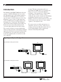
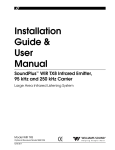
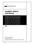
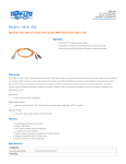
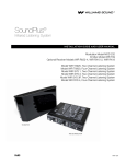
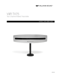
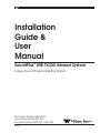
Installation
Guide &
User
Manual
SoundPlus® WIR TX300 Infrared System
Large Area Infrared Listening System
Modulator Model WIR MOD 1
Transmitter Model WIR TX3
Receiver Models WIR RX1, RX3, RX4
MAN 046C
®
Williams
Sound
Helping People Hear
SoundPlus® WIR TX300 Infrared Listening System
Installation and User Manual
Contents:
Page
Introduction
4
Controls and Features
MOD 1 Front Panel
MOD 1 Rear Panel
TX3 Transmitter
5
5
6
Infrared Transmitter Setup
Selecting a Transmitter Location
Mounting TX3 Transmitter To Wall or Ceiling
Transmitter Power Wiring
95 kHz Carrier Cable Connection
7
8
9
10
Modulator Installation
Power Connection
95 kHz Carrier Cable Connection
Audio Source Connection
Using a Microphone
Hi-Pass Filter Setting
10
11
11
11
11
Testing the System
12
Receiver Instructions
12
Battery Information
13
Suggestions For Receiver Management
14
Troubleshooting
14
Warranty
14
Specifications
15
Note: Taking a few minutes now to read these instructions will save time and ensure proper
system operation.
Williams
Sound ®
Helping People Hear
3
A single TX3 infrared transmitter will cover
approximately 10,000 square feet of listening area.
Larger areas can be covered with additional
transmitters. The transmission is confined within
opaque walls if security is an issue, such as
courtrooms and corporate boardrooms. The Williams
Sound Infrared System can also be used where
multiple systems are needed in adjacent rooms, such
as movie theaters and conference centers, without
“spillover” from adjacent rooms.
Introduction
The Williams Sound WIR TX300 Infrared System
consists of a MOD 1 Modulator and one or more
TX3 Transmitters (also called emitters) which use
invisible infrared (IR) light waves to broadcast
speech or music to wireless infrared receivers. The
Modulator accepts a variety of audio inputs and
sends a 95 kHz frequency modulated signal to the
Transmitter via a coaxial cable. The Transmitter
emits invisible infrared light into the listening area.
Infrared receivers detect the transmission and
convert the light signals back into audio signals.
The system is designed to broadcast high quality
audio for hearing assistance and language translation
applications. Because the system uses infrared light
for transmission, it is not affected by interference
from radio equipment and does not interfere with
radio equipment.
The system can be used with a microphone as a
stand-alone system, or it can be connected to an
existing sound system. Infrared Systems cannot be
used in bright sunlight, which contains large
amounts of interfering infrared light.
Fig. 1: Typical System Configurations
(1) Modulator and (1) Transmitter
TX3
MOD 1
MOD 1 Infrared System Modulator
Williams Sound
I
Power
Audio Level
Infrared
Test Out
Tape
Out
Mod Out
0
Ok
Hi
Williams
Sound ®
Helping People Hear
+
Adjust
Mod In
Power
Supply
(1) Modulator and (2) Transmitters
Power Supply
TX3
TX3
MOD 1
Williams Sound
MOD 1 Infrared System Modulator
I
Power
Audio Level
Infrared
Test Out
Tape
Out
Mod Out
0
Ok
Hi
Mod In
Power
Supply
Mod In
Mod Out
Power Supply
Modulation Signal
4
Williams
Sound ®
Helping People Hear
Williams
Sound ®
Helping People Hear
+
Adjust
Power
Supply
Modulation Signal
Williams
Sound ®
Helping People Hear
Balanced Line-Level Input:
Controls and Features:
Female XLR jack for balanced, line-level inputs.
Can also accept unbalanced input, and 4Ω, 8Ω, or
16Ω speaker line.
MOD 1 Front Panel
Power Switch:
Turns modulator power on/off.
70V (Hi-Level) Input:
Power Indicator:
Female XLR jack for direct connection to a 70V or
25V speaker line.
Green LED indicates power on.
Input Level Switch:
Audio Level Indicators:
“Ok” amber LED indicates proper audio input level.
“Hi” red LED indicates excessive audio input level.
Three-position switch selects mic-level, line-level, or
70V input for the XLR input jack.
Unbalanced Audio Inputs:
Audio Level Control:
Screwdriver rotary adjustment for audio input level.
Infrared Test LED:
Infrared LED provides a modulated IR signal for
receiver testing, monitoring, audio source testing.
Two RCA jacks for unbalanced line-level audio
inputs. Inputs are mixed internally with the balanced
input signal.
High-Pass Filter:
Three position switch provides 6dB/octave lowfrequency roll-off to reduce noise, improve speech
intelligibility, compensate for typical high-frequency
hearing loss.
Tape Output:
RCA Jack provides unbalanced, line-level audio
output signal for tape recorders, etc.
Modulator Outputs:
MOD 1 Rear Panel
Two F-type connectors provide 95 kHz frequency
modulated outputs to feed two TX3 Transmitters.
Balanced Microphone-Level Input:
Female XLR jack for use with low impedance (150 200Ω) microphones. Supplies simplex DC power
per DIN 45596 for condenser microphones.
Power Input:
Two-screw terminals for low-voltage power supply,
24VAC, 50 or 60Hz, 2.4VA.
Fig. 2: MOD 1 Front & Rear Panels
Williams Sound
MOD 1 Infrared System Modulator
I
Infrared
Test Out
Audio Level
Power
Tape
Out
0
Ok
+
Adjust
Hi
Model WIR MOD1 Infrared System Modulator
Audio Input
Balanced
Audio Inputs
Input Level
Hi-Pass Filter
Williams
Sound ®
Helping People Hear
75 Ohm
75 Ohm
Power: 24 VAC,
50-60 Hz, 10VA
175 Hz
70V
Right
Plug
725 Hz
20 Hz
Left
Made in USA
Modulator
Out
Unbalanced
Line
Mic
Modulator
Out
6dB/octave
Williams Sound Corp.
Power: 24 VAC, 60 Hz, 50VA
5
Fig. 3: TX3 Front & Rear
Williams
Sound ®
Helping People Hear
Infrared Transmitter
Omnimount
25-STXMP
Model WIR TX3
For Ceiling Mount
Power Supply Wiring:
Use NEC, Class 2 Wiring,
18 ga. Min
200 ft. Max. Length (18 ga.)
Internal Fuse:
1.25 A, 250V, 3AG
Modulation Signal Wiring:
Omnimount
25-STXMP
For Wall Mount
Use RG59U Coax,
1000 ft. Max. Length
CAUTION
Note: It is normal for this unit
to feel warm while it is in
operation.
Modulation Out
(75 Ohm)
RISK OF ELECTRIC SHOCK
DO NOT OPEN
WARNING: TO REDUCE THE RISK OF FIRE OR
ELECTRIC SHOCK DO NOT EXPOSE THIS
EQUIPMENT TO RAIN OR MOISTURE.
Modulation In
(75 Ohm)
Williams Sound Corp., Minneapolis, Minnesota, USA
Williams
Sound
Helping People Hear
Made in U.S.A.
®
TX3 Front
TX3 Transmitter
Power Input:
Two–screw terminal strip for low-voltage power
supply. 24VAC, 50 or 60Hz, 50VA. Each TX3
requires a separate power supply.
Power Indicator LED (front panel):
Located on the front panel in the center of the LED
window. Red indicator light glows when power is on
and the 95 kHz carrier is present.
TX3 Rear
Step 1: Infrared Transmitter
Set-Up
Selecting a Transmitter Mounting
Location
Rule 1:
The Williams Sound Infrared System
should not be installed outdoors or indoors
where there is considerable direct sunlight.
Sunlight generates infrared interference.
Certain types of high-efficiency
fluorescent lighting use 100kHz
modulation that can also interfere with
infrared systems.
Rule 2:
The most important principle to
understand when installing an infrared
system is that invisible infrared light
behaves just like visible light. It does not
pass through opaque objects like walls and
curtains and people. It does pass through
windows and door openings and it can
bounce and scatter off reflective walls,
floors, and ceilings. The IR transmitter
panels cannot be concealed or covered up.
The IR “eye” on the receiver unit cannot
be covered up and works best with a clear
line-of-sight to the transmitter panel(s).
Rule 3:
If you are not getting sufficient coverage
with a properly installed transmitter panel,
you need to add one or more additional
transmitter panels.
NOTE: The TX3 shuts off when no 95 kHz carrier
is present.
Modulation In:
Connects to the Modulator Out jack of the MOD 1
modulator or another TX3 transmitter.
Modulation Out:
Connects to the Modulation In jack of of the next
TX3 transmitter in the chain when multiple
transmitters are used.
Mounting Bracket:
An omnidirectional mounting bracket is included
with the Transmitter. Positions are indicated for wall
and ceiling mounts. An optional tripod stand kit is
also available (WSC Part #SS-2).
6
24 VAC Power In,
50-60 Hz, 35W
Williams
Sound ®
Helping People Hear
Figures 4, 5, and 6 illustrate infrared light patterns
and recommended transmitter locations. In listening
areas up to 10,000 square feet, the TX3 transmitter
panel should be installed on the left or right side of
the front wall of the listening area It needs to be
above the audience to permit a direct line of sight
between the transmitter and people wearing receivers
when the people are standing or sitting.
Fig. 4: Infrared Illumination Pattern
250 ft.
130 ft.
25°
25°
TX3
It’s helpful to think of the IR transmitter as an
invisible floodlight. You want to aim it so listeners
are “flooded” with infrared light.
Many listening areas will require two IR transmitters
for complete coverage. Place one transmitter panel
on the left side of the front wall and the other on the
right hand side. The two transmitters will be
connected together with a coaxial cable.
The infrared illumination pattern from a single
transmitter is a cone-shaped beam, with a 50° angle.
The horizontal and vertical patterns are identical.
Figures 4 and 5 show examples of coverage patterns.
Fig. 5: Maximizing Coverage
These patterns are the direct radiation pattern. The
infrared radiation does not drop to zero outside the
illustrated patterns; it decreases. It still may be
useable at a greater distance, depending on receiver
sensitivity and reflection characteristics of the room.
Top Perspective
Infrared light reflects off light-colored surfaces and
scatters, which increases the coverage area. Dark
colored surfaces tend to absorb infrared light,
minimizing reflections, and limiting coverage to the
direct illumination pattern. It’s O.K. (and desirable)
for the illumination patterns to overlap when
Using Two Transmitters For Greater Coverage Area
Fig. 6: Side Perspective
120'
Center
ter Bea
Of Emit
m
30'
SCREEN
6'
STAGE
Williams
Sound ®
Helping People Hear
7
multiple transmitters are used. Placing the
transmitter high above the audience (15 to 30 feet)
and aimed slightly downward (5 to 15°) will ensure
the longest “throw” of the infrared beam. Angling
the transmitter inward towards the center of the room
also increases the coverage of the seating area.
Remember that opaque objects block the infrared
light. Thus, transmitters cannot be concealed behind
an opaque walls, curtains, etc. Neither should
transmitters be used in areas of extreme high or low
temperatures, humidity, or chemical environments.
Fig. 7: SB-3 Wall/Ceiling Mount
Mounting Plate
Clamp Plate
To
Wall
Or
Ceiling
Use the 5/32" allen wrench to loosen the
tension bolt in the clamp assembly enough
to release the ball. DO NOT unscrew the
tension bolt completely. Using the
mounting plate as a template, mark the
hole locations on the mounting surface.
Use fasteners appropriate for the mounting
surface (wood screws, lag bolt, wall
anchor) to attach the mounting plate.
Recommended fastener size is 1/4".
Step 2:
Attach the clamp plate to the rear of the
transmitter, using (2) 1/4 x 20 x 1/2"
socket head screws and 3/16 hex wrench
provided. Place the mounting plate in the
position indicated for ceiling or wall
mounting.
Step 3:
Place the transmitter/clamp plate assembly
onto the the mounting plate ballshaft. Aim
the transmitter at the desired downward
angle and support it fully while using the
hex wrench to tighten the tension screw.
After initial installation, the ball will
slowly compress under pressure. Check
the tension screw after 15 minutes and retighten if necessary. DO NOT overtighten.
If rotational adjustment is required, use a
7/16" open-end wrench to loosen the jam
nut on the ballshaft. Rotate the transmitter
and re-tighten the jam nut.
8
To
Transmitter
Jaw
Mounting the TX3 to a wall or ceiling:
Step 1:
Ballshaft
Tension Screw
Fig. 8: Bracket 012 Ceiling Mounting
Fig. 9: Bracket 012 Wall Mounting
Jam Nut
Front of TX3
Williams
Sound ®
Helping People Hear
spade terminals supplied. Connect one end
of the zipcord to the transmitter power
input screw terminals. Connect the other
end to the power supply screw terminals.
Step 2: Transmitter Power
Wiring
WARNING! BE SURE AC POWER IS TURNED
OFF AT THE OUTLET WHILE INSTALLING THE
POWER TRANSFORMER. A METAL COVER
PLATE COULD SLIP AND SHORT ACROSS THE
TRANSFORMER PLUG DURING INSTALLATION,
CREATING A SHOCK HAZARD.
Step 2:
SHORTING THE POWER SUPPLY TERMINALS
WILL BLOW A NON-REPLACEABLE INTERNAL
FUSE, DESTROYING THE POWER SUPPLY
UNIT1
Make sure to.switch AC power to the
outlet OFF at the fuse or circuit breaker.
Remove the wallplate cover screw and
plug the transformer into the outlet.
Secure the transformer with the cover plate
screw. Turn the AC power back on at the
breaker box AFTER the transformer is
installed.
The indicator light on the front panel of
the TX3 will not glow unless there is a
95 kHz carrier. This auto shut-off feature
preserves the life of the IR LED’s and
reduces power consumption when the
transmitter is not in use. The wall
transformer can be plugged into a switched
outlet that turns on when the other sound
equipment is turned on. This system is
designed for Class 2, low-voltage wiring.
Always follow local electrical codes when
doing low voltage wiring.
The TX3 transmitter is supplied with a low-voltage
wall transformer power supply. The transmitter must
be located within 6 feet of an AC wall outlet or the
24 Volt power cord must be extended. Additional
two-conductor, 18 ga. zipcord is included with the
transmitter. If the transmitter power supply can be
located near the modulator, use the combination
cable to carry the modulation signal and low-voltage
power to the transmitter. The zipcord can be
separated
from® the combination cable if the power
Williams
Sound
Infrared Transmitter
Omnimount
Helping People Hear
25-STXMP
supply is located near the transmitter.
Model WIR TX3
For Ceiling Mount
DO NOT CONNECT THE POWER SUPPLY TO
AC POWER YET!!!
Step 1:
Determine the length of zipcord needed to
from the transmitter to the AC wall
Use NEC, Class 2 Wiring,
18 ga. Min
outlet where the power supply will be
200 ft. Max. Length (18 ga.)
Omnimount
plugged in. Cut the
zipcord to length.
Internal Fuse:
25-STXMP
1.25 A, 250V, 3AG
Zipcord length For
must
not exceed 200 feet.
Wall Mount
Modulation Signal Wiring:
Use RG59U Coax, Strip the ends and install the crimp-on
Power Supply Wiring:
reach
1000 ft. Max. Length
CAUTION
Note: It is normal for this unit
to feel warm while it is in
operation.
Modulation Out
(75 Ohm)
Fig. 10: TX3 Wiring Detail
RISK OF ELECTRIC SHOCK
DO NOT OPEN
WARNING: TO REDUCE THE RISK OF FIRE OR
ELECTRIC SHOCK DO NOT EXPOSE THIS
EQUIPMENT TO RAIN OR MOISTURE.
Modulation In
(75 Ohm)
Williams Sound Corp., Minneapolis, Minnesota, USA
24 VAC Power In,
50-60 Hz, 35W
Made in U.S.A.
Baseband Output Connection
Power Connection
Connect to MOD 1 here
using RG-59 cable.
Plug in Power Supply
Williams
Sound ®
Helping People Hear
9
Step 3:
Step 3: 95 kHz Carrier
Cable Installation
Step 1:
Determine the length of RG59 coaxial
cable needed to reach from the transmitter
to the modulator unit. The modulator is
usually located near the other sound
equipment to simplify audio connections.
100 feet of coaxial cable is included with
each transmitter. You will need to cut it to
length and install F-connectors on both
ends. Additional RG59 coax can be added,
up to 1000 feet maximum. Make sure you
leave some slack at each end.
Step 2:
Install the F-connectors on each end of the
cable. You will need a CATV-type coax
stripper and crimper.
Step 3:
Connect the 95 kHz carrier cable to either
Modulator Out jack on the MOD 1
modulator and to the Modulator In jack on
the TX3 transmitter.
Connect the modulation cable from the
Modulation Out Jack on the first
transmitter in the chain (the one connected
to the MOD 1 Modulator) to the
Modulation In jack on the next TX3
transmitter in the chain. Use the cable
clamps and screws provided to secure the
cable. The coax can also be routed through
conduit. You can chain as many
transmitters together as you need.
Remember that each transmitter needs its
own power supply.
If you are using more than one transmitter:
Step 1:
Determine the length of coaxial cable
needed to reach between the transmitters.
100 feet of coaxial cable is included with
each transmitter. You will need to cut it to
length and install F-connectors on both
ends. Additional RG59 coax can be added,
up to 1000 feet maximum. Make sure you
leave some slack at each end.
Step 2:
Install the F-connectors on each end of the
cable. You will need a CATV-type coax
stripper and crimper.
Fig. 11: Modulator Wiring Detail
Model WIR MOD1 Infrared System Modulator
Audio Input
Balanced
Audio Inputs
Input Level
Hi-Pass Filter
Line
Mic
Modulator
Out
Power: 24 VAC,
50-60 Hz, 10VA
175 Hz
70V
Left
Right
Plug
725 Hz
20 Hz
Made in USA
10
Modulator
Out
Unbalanced
6dB/octave
Williams Sound Corp.
75 Ohm
75 Ohm
Power: 24 VAC, 60 Hz, 50VA
Baseband Output Connection
Power Connection
Connect to TX3 here using RG-59 cable.
Plug in Power Supply
Williams
Sound ®
Helping People Hear
Step 4: MOD 1 Modulator
Installation
Location:
The Modulator is usually located near the sound
system amplifier or mixer for easy access to an audio
input signal. For portable systems, the modulator can
be placed near the transmitter or wherever is most
convenient.
Power Connection
Step 1:
Connect the power supply wires to the two
center screw terminals on the terminal
block located on the rear of the Modulator.
Step 2:
Plug the power supply into an AC outlet.
95 kHz Cable Connection
Connect the coaxial cable to either F-type
“Modulator Out” jack on the MOD 1. For systems
having multiple transmitters, both modulator outputs
can be used to run a separate coax cable to
transmitters on each side of a stage, screen, etc. The
MOD 1 drives one transmitter per modulator output.
The transmitters then repeat the 95 kHz signal, so
any number of transmitters can be used. The
modulator outputs CANNOT be split with CATV
splitters.
Audio Connection
Mono, Unbalanced Source:
Use the RCA to RCA audio cable supplied to
connect either MOD 1 unbalanced “Audio Input”
jack to an appropriate unbalanced, line-level audio
output jack on the sound system mixer or amplifier.
Suitable connections are:
1st Choice:
TAPE OUT or LINE OUT Jack
2nd Choice:
BOOSTER or BRIDGING Jack
If your amplifier or mixer does not have RCA-type
connectors, you can obtain adaptors from your
Williams Sound Authorized Dealer or a local radio
parts store. If the TAPE OUT jack is already in use,
a Y-Cord can be used to connect the MOD 1 and a
second device to the same jack.
Williams
Sound ®
Helping People Hear
Stereo, Unbalanced Source:
For stereo sources, use an additional RCA to RCA
cable and connect the left and right signals to the two
inputs on the MOD 1. They will be mixed into a
mono signal for transmission.
Three–Channel, Unbalanced Source
(Left, Right, Center Channel):
Set the input level switch to “Line.” Use the two
unbalanced inputs and the XLR balanced input. You
will have to make an RCA to XLR adaptor cable. To
unbalance the XLR input, wire XLR pin 2 to the
positive audio pin on the RCA plug and wire XLR
pin 1 and pin 3 together to the audio ground sleeve
on the RCA plug. The three signals will be mixed
into a mono signal for transmission.
Balanced, Line–Level Source:
Set the Input Level Switch to “Line.” The XLR input
jack can be connected to any balanced, line-level
audio signal. It has an input impedance of
100 KOhms, so it will not load the signal.
Balanced, Microphone Source:
Set the Input Level switch to “Mic.” Any lowimpedance, balanced microphone can be plugged
into the XLR input jack. Simplex power is supplied
for condenser microphones.
4 or 8 Ohm Speaker Line Source:
Set the Input Level Switch to “Line.” Wire an
adaptor cable with the positive speaker line
connected to XLR pin 2. Connect the negative or
ground speaker line to XLR pin 3.
25 or 70V Speaker Line Source:
Set the Input Level Switch to “70V.” Wire an adaptor
cable with the positive speaker line connected to
XLR pin 2. Connect the negative or ground speaker
line to XLR pin 3.
Hi-Pass Filter Setting
The normal setting is the center (175Hz) position.
For language interpretation or visual description, the
20Hz setting can be used. For hearing assistance, the
725Hz setting can be used to compensate for typical
high-frequency hearing loss. Ask the users what
sounds best to them.
11
Step 5: Testing the System
Step 1:
Step 2:
After the 95 kHz carrier cable, power
cables, and audio source are connected,
turn the MOD 1 power switch on. The
green LED on the front of the MOD 1
should light.
Make sure the sound system is on and your
audio source is active. Adjust the Audio
Level control on the front of the MOD 1
until the “OK” light flashes with the audio
signal. It is okay if the red “Hi” light
flashes occasionally, but it should not stay
lit constantly. If you can't get the “Ok”
light to come on, make sure the Input
Level switch is set properly. If it is, you
need to boost the signal source.
Receiver Operating
Instructions
Receiver Model WIR RX1
The RX1 is a stethoscope-style receiver with built-in
earphones. Make sure the “eye” on the front of the
receiver is not covered up when in use. The receiver
is intended to be worn on the front of the body,
hanging from the ears.
Step 1:
Battery Installation: The RX1 uses two
AAA Alkaline batteries. To insert, remove
the cover, press the batteries into
place,then replace the cover.
Step 2:
Turn the power on by rotating the volume
control. Continue rotating until a
comfortable volume level is reached. To
avoid draining the battery, make sure the
receiver is turned off when not in use.
Step 3:
Look at the transmitter panel(s). With the
modulation signal and power connected, a
red light should be visible in the center of
the panel.
Step 4:
Hold a receiver near the “Infrared Test
Out” hole on the front of the MOD 1. Turn
the receiver on and adjust the volume. You
should be able to hear the audio signal
through the receiver. If not, make sure the
audio “Ok” light is still flashing. If the
light is not flashing, check your audio
source or the setting of the input level
switch and input level control. If the audio
light is flashing, but you don’t hear
anything from the receiver, try a different
receiver to make sure the receiver is
working.
Make sure the “eye” on the front of the receiver is
not covered up when in use. The receiver is intended
to be worn on the front of the body, hanging from the
lanyard attached to the receiver. The receiver will not
work if it is placed in a pocket or purse. A variety of
earphones, headphones, or a neckloop telecoil
coupler can be used with the RX3 Receiver.
Step 1:
Battery Installation: Open the battery
compartment by lifting the tab at the
bottom of the receiver. Press the battery
into place, observing proper battery
polarity.
Take a receiver into the listening area and
walk around to check the reception. Make
sure the “eye” on the receiver is not
covered up when in use. The receiver will
not work if it is placed in a pocket or
purse. The receiver eye must be able to
“see” the transmitter panel. It may be
necessary to adjust the angle of the
transmitter(s) to obtain the best coverage.
If coverage is not adequate, additional
transmitter panels must be used.
Step 2:
Plug the earphone or headphone into the
earphone jack.
Step 3:
Turn the receiver on by rotating the
volume control in the direction of the
arrow on top of the case. Turning the knob
in the direction of the arrow will increase
the volume. Turning the knob against the
arrow will decrease the volume. To avoid
draining the battery, make sure the receiver
is turned off when not in use.
Step 5:
12
Receiver Model WIR RX3
Williams
Sound ®
Helping People Hear
Receiver Model WIR RX4
The RX4 is a headset-style receiver. Make sure the
“eye” on top of the receiver is not covered up when
in use.
Step 1:
Step 2:
Battery Installation: Open the battery
compartment by sliding the battery door
open on the earpiece. Press two AAA
batteries into place, observing proper
battery polarity. Slide the battery door
closed, taking care not to crush the plastic
locking tabs.
Turn the power switch on top of the
receiver on. Adjust the volume control
wheel located on the bottom of the
headset.
leaving the receiver on for several hours and then
immediately recharge it.
Receivers can be left charging continuously when
not in use.
DO NOT ATTEMPT TO RECHARGE DISPOSABLE
BATTERIES!
AVOID SHORTING PLUS AND MINUS BATTERY
TERMINALS TOGETHER WITH METAL OBJECTS.
BATTERY DAMAGE AND BURNS CAN RESULT!
DO NOT MIX RECHARGEABLE BATTERIES &
CHARGERS FROM DIFFERENT
MANUFACTURERS.
Battery Information for Receivers
For the RX3 Receiver in normal use, a heavy-duty 9
Volt battery such as the Eveready 216 will last about
10 hours. Alkaline batteries such as the Eveready
522 will provide about 17 hours of use. For the RX4,
alkaline AAA batteries will last about 20 hours. If
the sound becomes weak or distorted, replace the
battery. The indicator light may still be on, even
with a battery that is weak. Do not leave dead
batteries in the receivers, they may leak and damage
the receiver.
Rechargeable Batteries:
The RX3 receivers can also use a rechargeable
battery. We recommend only the 7-cell, 8.4 Volt
types
(BAT 003). A fully-charged battery (Williams BAT
003) will provide about 5 hours of use per charge.
The battery may be recharged without removing it
from the receiver.
The BAT 005 Single Charger has a cord that plugs
into the receiver “EAR” jack to charge the battery.
The CHG 1269 Multiple Charger can charge 12
receivers simultaneously through the receiver “EAR”
jacks.
The receiver should always be turned OFF while
charging. It takes about 14 hours to fully charge the
battery. If the battery is providing very short service
life (under 1 hour of use) let it drain completely by
Williams
Sound ®
Helping People Hear
13
Suggestions for Receiver
Management:
Different types of facilities will use different
approaches for receiver management and earphone
sanitation. Following are some alternatives that other
customers have used successfully:
1.
Regular users purchase their own receiver and
take care of their own batteries and earphone.
2.
Some facilities label the receiver and earphone
with the names of regular users so each person
uses the same receiver and earphone.
3.
Ushers issue receivers to people who request
them. Earphones are sanitized after use. Foam
ear cushions can be replaced or washed with a
mild detergent, rinsed thoroughly and airdried. The EAR 022 Surround Earphone can
be sanitized with an alcohol pad.
4.
The receivers are stored in a multiple
compartment storage case with a credit card or
driver's license left as collateral for the
receiver.
5.
Regular users purchase their own earphone or
headphone and bring them to use with
receivers at the facility.
2.
If none of the receivers work, check to see if
the power and 95 kHz carrier cable are
connected to the transmitter and the “Power”
like is ON.
3.
Check to see if the modulator is connected
properly to the sound system. The audio level
lights should be flashing on the modulator.
4.
Make sure the “eye” is not covered up on the
receiver. There must be clear line of sight
between the receiver eye and the transmitter
panel.
Sound through the receivers is weak
and noisy.
1.
Hold a receiver in front of the Infrared Test
LED on the front of the MOD 1 modulator and
listen to the signal. If the signal is weak and
noisy here, check the Input Level switch and
Input Level Control settings. Increase the input
signal level from the sound system by turning
up a mixer control. If the signal sounds okay,
you may need to re-position the transmitter
panels or add additional panels.
Buzzing or humming noise in sound
system.
1.
Check for ground loops or noise on the input
signal. Call your Authorized Dealer or
Williams Sound for help.
Troubleshooting:
Transmitter “Power” light not on.
1.
Make sure the wall transformer is plugged into
the transmitter and the power switch or any
remote power switch is on..
2.
Make sure the electrical outlet is on.
3.
Make sure the MOD1 is on. The TX3 shuts off
when there is no 95kHz modulation signal.
4.
Make sure the 24VAC power supplies are
working.
No sound through receivers.
1.
14
If some of the receivers work but others don’t,
check for bad batteries or earphones on the
receivers that aren’t working.
Warranty
Williams Sound Transmitters and Receivers are
warranted against defects in workmanship and
materials for FIVE YEARS. Microphones,
earphones, cables, carry cases, rechargeable batteries
and chargers are warranted against defects in
workmanship and materials for 90 DAYS. This
warranty does not extend to intentional or accidental
physical damage. This warranty applies only to
products returned to Williams Sound for service. To
return a product for service, call Williams Sound
Corp. at 1-800-843-3544 and request a Return
Authorization (RA) number.
Williams
Sound ®
Helping People Hear
SoundPlus™ WIR TX300 Infrared Listening System Specifications
Infrared Audio Processor/Modulator, Model MOD 1
Dimensions, Weight:
Color:
Rack Mount:
Power:
Modulation:
AGC:
Operating Req.:
8.45" (21.5 cm) W x 8.18" (20.8 cm) D x
1.72" (4.4 cm) H, 3 lbs. (1.5 kg)
Black epoxy paint with white legends
One IEC rack space high, one or two
units can be mounted in a single rack
space with optional RPK 005 (single) or
RPK 006 (double) Rack Mount Kits
External power supply, 24VAC, 50 or
60Hz, 2.4VA, 82mA max. current drain
95kHz FM, ± 15kHz deviation, 75Ω source
impedance, 75µsec pre-emphasis,
Variable slope compressor/limiter
0-50°C ambient temperature, noncondensing, non-corrosive atmosphere
Front Panel:
Power Switch:
Power Indicator:
Audio Indicators:
Two-position rocker, ON/OFF
Green LED
Amber LED "Ok" for nominal input signal
level
Red LED "Hi" for excessive input signal level
Audio Level Control:
Rotary pot, screwdriver adjust, used
with audio indicator lights
Tape Output:
RCA jack, 600mV, 1200Ω source
impedance, 10KΩ nominal load
impedance
Infrared Test LED:
IR LED for receiver testing, monitoring,
and audio signal testing
Rear Panel:
Audio Inputs:
All three inputs are actively mixed into a
single signal, allowing use of mono,
stereo, or 3 channel audio sources
Balanced Audio In:
3-pin female XLR, accepts microphone,
line, 25V or 70V audio input
Mic Input:
lo-Z, 100µV min. to 50mV max. 1mV
nominal, 3kΩ input impedance Supplies
simplex power 20V (DIN45296) for
condenser mics
Line Input:
21mV min. to 10V max., 212mV nominal,
100KΩ input impedance
70 Volt Input:
216mV min. to 100V max., 2.16V
nominal, 100KΩ input impedance
Unbalanced Audio Ins: (2) RCA, 21mV min. to 10V max., 212mV
nominal, 50KΩ input impedance
Input Selector:
3-position slide-type switch, selects:
mic/line/70V on balanced audio input
High-Pass Filter:
3-position slide-type switch, 20Hz, 175Hz,
or 725Hz, 6dB/octave roll-off
Modulation Outputs:
(2) F-type connectors, 75Ω, 95kHz FM,
±15kHz deviation, 0.5V P-P signal uses
RG-59 cable, 1000 ft. (304 m) max.
CATV splitters cannot be used
Power Connections:
2-conductor, screw-terminals
Transmitter Type:
For use with Williams Sound WIR TX1, WIR
TX2, WIR TX3 Transmitter/Emitter panels.
Each MOD 1 Modulator can drive two
Transmitter panels directly. For multitransmitter systems, each TX3 repeats
the modulation signal to drive the next
transmitter in the chain.
Infrared Transmitter, Model TX3
Dimensions, Weight:
Color:
Wall Mount:
Tripod Mount:
Power:
Operating Req.:
Coverage Area:
11.125" (28.3 cm) W x 8.125" (20.6 cm)
H x 3.25" (8.3 cm) D, 3.25 lbs. (1.6 kg)
Black epoxy paint with white legends,
red acrylic window
Omnidirectional mount included for
wall and ceiling mounting.
Optional SS-2 Tripod Stand Kit available
External power supply, 24VAC, 50 or
60Hz, 50VA, 0.9A nom. current drain
Transmitter shuts off when modulation
signal is not present
0-50° C ambient temperature, noncondensing, non-corrosive atmosphere
10,000 sq. ft. (930 sq. m), 50° cone
pattern, see coverage diagram
Williams
Sound ®
Helping People Hear
TX3 Front Panel:
Power Indicator:
Red LED, visible in center of window,
also indicates 95 kHz signal is present
TX3 Rear Panel:
Mounting Holes:
Modulation Input:
Modulation Output:
Power Connection:
95 kHz Carrier Cable:
Power Cable:
Two sets of threaded holes for use with
omnidirectional mount (included) two
threaded holes on sides of the cabinet
for Tripod Stand Kit
F-type connector, 75Ω, 95kHz FM, 0.5V
P-P signal from MOD 1 Modulator
F-type connector, 75Ω, 95kHz FM, 0.5V
P-P signal output to additional TX3
2-conductor, screw-terminals
RG-59 Coax, F-connectors
NEC Class 2 wiring, 2-conductor, 18 ga.
min., 200 foot (61 m) max. length (for
18 ga. wire), each TX3 Transmitter
requires its own 24VAC Power Supply.
15
Williams Sound Corp.
10321 West 70th St., Eden Prairie, MN 55344-3446
U.S.A. 800-843-3544 / 952-943-2252 / FAX: 952-943-2174
© 1996, Williams Sound Corp. MAN 046C