1
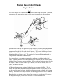
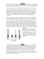
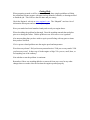
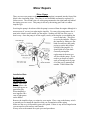
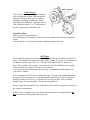
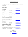
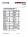
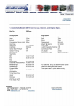
GEMINI/WESTERBEKE OWNERS SEMINAR
Introduction
1. Engines1 Personnel
2. Products
Basic Engine Theory
1. Diesel Engines
2. Transmissions
System Description/Checks
1 Fuel
2 Water, Fresh
3 Water, Raw
4 Exhaust
5 Electrical, DC
6 Getting Help
Minor Repairs
1. Water Pumps
2. Filter Changes
3. V-Belt Changes
4. Oil Types
5. Tool List
Scheduled Maintenance
1. Fluid Levels
2. Valve Adjustment
3. Cylinder Head Torque
4. Winterizing/Spring Commissioning
Spare Parts
1. Emergency Spares
2. General Spares
ENGINES1
History
Engines1 began its now 42-year venture as a sales/service support division of a local shipyard.
The shipyard had a small yacht repair facility in Norfolk, VA that was in need of engines and
parts to be competitive with engine repair.
Over the years as the business grew and the products were taken to market at a distribution level
it became clear that the 4 man department was more than just a support for the yard.
As time went on the “Norshipco Engine Division” became a self sufficient and self supporting
part of the company. In 1988 the distributorship was given a name of its own, Norshipco Marine
Sales or NMS. In 1998 the shipyard underwent an ownership change and the engine department
was sold to Western Branch Diesel, Inc. Engines1 opened for business in March of 1999.
Keeping the people through the change Engines1 “hit the ground running” and we have not
looked back.
Our products are engine room related. Gasoline inboard engines. Gasoline and diesel generator
sets for both marine and industrial. Marine transmissions. Engine and transmission controls.
High end top of the line AGM batteries, Inverters, Battery Chargers, Power supplies, Fire
suppression equipment, and a host of support products and parts for each product line.
Our staff has a combined experience of over 125 years, and most have a mechanical (motor
head) background.
As always, Engines1 is big enough to serve you, yet small enough to know you. Even though we
are not perfect we still believe that we are set apart by our level of customer service.
DIESEL ENGINE THEORY
Diesel engines differ from other internal combustion engines in a number of ways.
Compression ratios are higher than in spark-ignited engines. The charge taken into the
combustion chamber through the intake consists of air only, with no fuel mixture.
Injectors receive fuel under pressure from the fuel pump and deliver it into the
combustion chambers at the right time in equal quantities and at the proper condition to
burn. The heat of compressed air in the combustion chamber causes the fuel mixture to
ignite. The most modern diesel engine has a four-stroke cycle. The four strokes and the
order in which they occur are: intake stroke, compression stroke, power stroke, and
exhaust stroke.
INTAKE STROKE
During the intake stroke, the piston travels downward. The intake valve is open, and the
exhaust valve is closed. The downstroke of the piston draws air in from outside to enter
the cylinder through the open intake valve ports.
Some engines use turbochargers to increase air pressure in the engine intake manifold,
which forces the air into the cylinder. The intake charge consists of air only with no fuel
mixture.
COMPRESSION STROKE
At the end of the intake stroke, the intake valve closes and the piston starts upward on the
compression stroke. The exhaust valve remains closed. The air that was drawn into the
cylinder is squeezed into the combustion chamber at the top of the cylinder.
At the end of the compression stroke, the air in the combustion chamber has been forced
by the piston to occupy a much smaller space than the space at the beginning of the
stroke. The compression ratio is a comparison, or ratio, of the volume of air in a cylinder
before compression with its volume after compression. For example, a 16:1 compression
ratio means air is squeezed into one sixteenth of the space at the top of the stroke that it
occupied at the bottom of the stroke.
Compressing the air into a small space causes the temperature of that air to rise. Near the
end of the compression stroke, the pressure of the air above the piston is approximately
400 to 500psi, and the temperature of that air is approximately 540°C.
During the last part of the compression stroke, and the early part of the power stroke, a
small, metered charge of fuel is injected into the combustion chamber. Almost
immediately after the fuel charge is injected into the combustion chamber, the fuel is
ignited by the hot air and starts to burn.
POWER STROKE
During the power stroke, the piston is pushed downward with both the intake and exhaust
valves closed. By the time the piston reaches the end of the compression stroke, the
burning fuel causes a further increase in the pressure above the piston. As more fuel is
added and burns, the gases get hotter and expand more to push the piston downward and
to add momentum to the crankshaft rotation.
EXHAUST STROKE
During the exhaust stroke, the intake valves are closed, the exhaust valves are opened,
and the piston is on its upstroke. Burned gases are forced out of the combustion chamber
through the open exhaust valve ports by the upward travel of the piston and by the
pressure differential at the exhaust outlet.
.
Proper engine operation depends upon two things; first, compression for ignition and
second, that fuel be measured and injected into the cylinder in the proper quantity and at
the proper time.
It takes two revolutions of the crankshaft to complete a cycle. Therefore, as piston one
starts its power stroke, it turns the crankshaft through 90° or one quarter of a revolution
(for an eight cylinder engine) before the second piston in the firing order starts its power
stroke. The third piston follows the second piston, and so on until after two full
crankshaft revolutions all pistons have started or completed a power stroke.
MARINE TRANSMISSIONS
Marine transmissions fall generally into two groups, mechanical shift or hydraulic shift.
Mechanical transmissions connect the input from the engine to the output of the shaft by
means of a mechanically operated assembly such as a dog clutch or shift fork that
mechanically moves the gears into the selected position. Hydraulic transmissions
connect the input from the engine to the output at the shaft by means of a hydraulically
operated piston, which clamps the clutches or friction plates together locking the input
shaft to the output gear.
Since we are focused on the Westerbeke product in the Gemini, we will stick with the
mechanically operated transmissions. Westerbeke model 30B-Three engines have been
assembled with three model transmissions. The earlier models used a Hurth model
HBW100. The current engines use a Westerbeke JS gear or a Newage PRM gear. While
all are mechanical transmissions they differ in their operations.
The Hurth Gear uses a servo-automatically controlled helical gear. The servo-operated
multiple disc clutch system requires only minimum effort to shift. The Hurth gear is
immersion lubricated. And maintenance is restricted to oil level checks, fluid changes
and visual inspections.
The JS transmission is similar to the Hurth. It, however, uses a cone clutch to engage the
gears. The JS gear also uses the immersion lubrication method. This transmission cannot
be shifted from full ahead to full astern. All shifting must be done below 1200 rpm’s.
When shifting any modern mechanical transmission used by Westerbeke, the lever must
be moved in a snappy motion, slowly moving the lever may not engage the clutches.
Fluid checks are simple. Remove the dipstick, wipe it clean, reinsert into transmission,
remove and check. The fluid level should be at the top mark on the dipstick.
Any indication of a malfunction can be either seen or smelled from the oil on the
dipstick.
System Description/Checks
Engine Systems
Fuel
On a diesel engine one of the most misunderstood systems is the fuel system. Consisting
of two major and several minor parts the fuel system is generally the most neglected.
When fuel leaves the tank it is pulled toward the engine by a primary fuel pump and then
forced under pressure through the secondary filter to the injection pump. The injection
pump pressurizes the fuel and sends it to the injector. This event is timed to perfection
with the rising of the piston on the power stroke so the fuel sprays at an exact moment
during the pistons travel to the top. The atomized fuel mixes with the superheated air
charge and the combustion event takes place.
On a regular basis, every engine owner needs to perform a visual check of the fuel
system. Looking for minor fuel leaks, bent tubing, or corrosion one can correct a small
problem before it becomes a serious problem. However, do not limit your visual check to
the engine. Check the system all the way to the tank, even the fuel fill tube, tank vent
system, all clamps and hoses.
All Westerbeke engines are equipped with at least one secondary fuel filter. This is
located in a small bowl mounted to the engine. Engines that are several years old, and
use the round electrical fuel pump, also have a filter mounted in the bottom of the pump
housing. These need to be changed as often as your large primary fuel filter is changed.
Remember the two biggest enemies of your fuel system are dirt and water. If you take
the inexpensive step to prevent these it will save a lot more down the road.
Fresh Water
The engine’s fresh water system, also know as the closed cooling system consists of a
circulating pump, heat exchanger, expansion tank, thermostat, and several hoses. This is
the system that cools
your engine. Water is
pulled from the heat
exchanger and pushed
into the engine’s water
jacket by the circulating
pump. When the block
and heads are full a tiny
amount of water
continues to circulate to
help maintain a
consistent temperature
in the exhaust manifold
and bleed air trapped in
the system. As the
internal engine
temperature begins to
rise the thermostat
opens and allows the
water to be pushed out of the system by a cooler charge of water pulled from the heat
exchanger. This will happen until the thermostat has cooled down and closes. The
process will then begin again. The expansion or holding tank is integral with the exhaust
manifold. It holds water that functions as a safety net so as not to stress the system.
Coolant in the system is a mixture of anti-freeze and water. Depending on your local
cruising climate this mixture may vary. Generally it is 50/50 or 1 part water to 1 part
anti-freeze. If you use the environmentally friendly anti-freeze the mixture may vary and
the specs should be on the bottle.
Closed cooling system checks are simple. The hoses should be soft yet firm with no
mushy spots or brittle spots. There should be no cracks in the hoses or fittings. Clamps
should be tight. The coolant should be topped off in the overflow bottle to the “Full Hot”
mark. The mixture should be maintained if you have to add fluid. The engine
temperature should range from
185° to 200° F. Any temperature
outside this range will generally
point to a thermostat problem.
The coolant should be changed
every 2 to 3 years. Hours are not
as critical as time and
deterioration will occur. Check
the v-belt that turns your
circulating pump. It should be
flexible and show no signs of
cracking. The tension should be so that the belt will flex between ½” and ¾” from side to
side. Tighten the v-belt as necessary.
The last item is the expansion tank cap. It serves two functions, 1 to allow coolant to
escape as the liquid expands from heat, and 2 to allow coolant to enter the engine as the
system cools. It should be easy to see what will happen if either of these functions did
not occur. At the least, check the system monthly.
Raw Water
The raw water system’s primary function is to cool the water used in the closed cooling
system. The raw water system consists of a pump and a couple of hoses. Combined with
a through hull fitting and strainer mounted off the engine. These are all that is involved.
The raw water pump has a rubber impeller that is rotated in a housing. In this housing
there is a cam that squeezes the rubber blades down and forces the water out of the
pumps outlet through the hose, and into the heat exchanger. As the raw water passes
through the heat exchanger it travels through the inside of a set of tubes. On the outside
of these tubes is where the anti-freeze solution passes. Heat is picked up through the
tubes and carried away with the raw water. When it leaves the heat exchanger the raw
water passes into the exhaust elbow and is mixed with exhaust gas and dumped
overboard.
On an annual basis you need to check the impeller inside the raw water pump. The
blades should flexible and straight. If the blades are bent or “set”, the impeller needs to
be replaced. While the impeller is out, check the pump’s inner housing. It should be a
shade of brass in color. The body should not have any copper color inside. This
indicates electrolysis and needs to be corrected. The cam in the pump should be smooth
and the ends should not be broken. When checking the pump inspect the housing’s
exterior. The pump has weep holes to let water drain if a seal should fail. There should
be no signs of water coming from these holes. The hoses in this system should also be
free from cracks and kinks. Since some of the hose is wire inserted it will not be as soft
as the closed system hoses. However, hoses that are not wire inserted should be checked
as before.
Check your zinc! This is your only on
engine protection from electrolysis.
Change it frequently. The zinc should not
deteriorate beyond recognition. After
several zinc changes, or once a season,
remove the end cover off of the heat
exchanger and clean out any old zinc and
other debris.
Exhaust
The exhaust elbow, water lift muffler, through hull outlet, and a few feet of hose are the
parts that make up the exhaust system. Since we discussed the manifold it will not be
repeated here. The purpose of the exhaust system is to take the spent exhaust gas and
discharge it from the boat. As the exhaust leaves the cylinder it travels through the
exhaust manifold and then through the exhaust elbow. At the end of the elbow it is
mixed with the raw water from the engine. This mix goes into the water lift, or as
sometimes called, aqualift muffler. As the muffler fills with water the outlet becomes
blocked. When this happens the pressure from the exhaust gas forces or blows the water
out of the muffler and out of the boat.
This system check should include the hoses and clamps as before. Also check the
muffler for cracks. If you have a rubber muffler check it for cracks and hardness of the
rubber parts. Also check the exhaust elbow and the attaching clamp. Check the fitting at
the hull and the clamps.
One caution to always follow is not to over crank the engine. If the engine does not
start in the normal cranking period turn the seawater valve to the off position. Failure to
do so will fill the muffler and ingest water into the engine.
DC Electrical System
The engine’s electrical system operates on 12 volts dc. The major components are the
battery, starter, alternator, fuel pump, glow plugs and solenoid, switches and instrument
panel.
System checks should include battery fluid level and belt tension. Periodically check
electrical connections for tightness and clean any corrosion. Since troubleshooting and
repairing the electrical system can be complicated, repairs should be limited to those
contained in the owner’s manual. A qualified marine mechanic should do all other
repairs.
Getting Help
When preparing to make a call for service, following these simple guidelines will help
the technician to better prepare with parts and any manuals, bulletins, or drawings needed
to finish the job. This will save the tech time and you money.
Check the Engines1 web site at www.engines1.com. The “Shoptalk” area has a lot of
information about parts and service for your engine.
Have your model and serial numbers handy and record your engine hours.
When describing the problem be thorough. Describe anything unusual that took place
prior to or during the failure. Did the problem occur all at once or was it gradual.
Also note anything that you have tried to repair yourself along with any parts or items
that you have checked.
If it is a power related problem note the engine speed and temperature.
Were there any alarms? Did you hear any unusual noises? Did you see any smoke? Did
you loose any water? Is there any oil in the engine or bilge? Do you see, smell, hear, or
feel anything out of the ordinary?
Note whether or not the problem is consistent.
Remember if there was anything added to or removed from your vessel or any other
changes that were made since the last time the engine operated properly.
Minor Repairs
Water Pumps
There are two water pumps on the engine. The pump that is mounted into the front of the
block is the circulating pump. This pump is not rebuildable and must be replaced if a
failure occurs. The second is the raw water pump mounted to the right hand side behind
the timing gear case cover. This pump is driven by the timing gears and is a rubber
impeller type.
Servicing the pump is best done while the pump is removed from the engine although it is
not necessary if you are just replacing the impeller. To remove the pump remove the 4
nuts in the corners used to attach it to the engine. Nothing will fall out of the case so
don’t worry. Once the pump is off the engine, start by removing the screws holding the
cover to the body. This gives
access to the impeller. Remove
the impeller by taking two flat
blade screwdrivers and gently
prying up on the hub (center
section) of the impeller. It
should slide off of the shaft.
Generally an impeller
replacement is the most you
will do with the pump. If you
need to go deeper to replace
seals or bearings refer to page
68 of the service manual part
number 37600 Edition One.
Installation Hints:
Do not use any
gasket sealer on
the impeller cover
gasket. Smear the
gasket surface with
some light grease or
petroleum jelly.
When installing a
new impeller rub a
coat of light grease
on the blades.
Remove the impeller when you winterize your engine. Place a tag on the battery switch
to remind you to reinstall the impeller when you recommission in the spring.
Make sure the cover is flat and not grooved or pitted. If there is any surface imperfection
you can sand on a flat surface until smooth.
Always refer to the manual for repair specs and procedures.
Filter Changes
Oil Filters:
If there is one thing you should remember it is this: Your oil is the lifeblood of your
engine. Cheap oil or old and dirty oil will lead to premature engine failure. Westerbeke
has made changing the oil very simple.
To change the oil start and run the engine for a few minutes to get it warm. This will
help the oil to flow better. Locate the oil drain hose attached to the front area of the
engine. Remove the cap from the end of the hose and place the hose in a container that
will hold a gallon of fluid. Once the oil has drained replace the cap on the hose and
reattach to the engine.
Installation Hints:
Use genuine parts. Aftermarket parts may fit, but we have had failures due to
incompatibility of parts. Especially oil filters. There is more to consider besides thread
and gasket surface matches
Use high-grade oil and advise your service tech to do the same. The few dollars saved on
low-grade oil will cost 100 times more in the long run.
When replacing the oil filter smear some oil on the o-ring seal and fill the filter half way
with new oil.
Change the oil at least once a season or every 100 hours. However it is best to change it
twice. One of these changes should be done at winter lay-up. Old oil has gathered
chemicals and combustion byproducts that can cause premature bearing and ring failure.
Refer to the manual for more detailed instructions.
Fuel Filters:
The Westerbeke engine uses either one or two fuel filters mounted to the engine. The
secondary, on engine filter is located in a cup mounted on the oil filter side of the engine.
Unscrewing the metal ring and gently pulling the cup down will give access to the filter.
The filter should stay on the filter body. Pull the filter off of
the body. There are two o-rings on this housing, one to seal the
inside of the filter to the housing, and the other to seal the cup
to the housing. There is an illustrated drawing on pages 39, 40,
and 41 of the Owner’s Manual, edition three. If so equipped
the other filter is located in the base of the fuel pump. The
pump will be round (not square). To remove the filter use a
17mm wrench on the base cap nut turning about 90°. The base
will come straight down and the filter is inside the pump.
There will be fuel spilled out when changing this type of filter.
New Westerbeke filters come with a complete set of both orings and/or gaskets. If these parts are not in the new filter
packages, shop at some other store, you are not being sold
genuine parts.
Installation Hints:
When replacing fuel filters turn your battery switch to OFF.
Use a gentle touch. If you strong-arm small parts you will have
to replace more damaged pieces.
Westerbeke Engines are self-bleeding. After a fuel filter change hold your preheat button
in for a minute or so and the fuel system will fill itself. However when replacing your
large off engine mounted fuel filter/water separator it is always a good idea to fill this
with fuel.
After the old filters are removed, inspect the old filters for signs of problems.
V-Belt Changes
The V-belt on your engine turns the alternator
and circulating water pump. Belts should be
replaced when they show signs of cracking,
shredding, stretching, or hardening. When
replacing the belt all that is required is tension.
There should be about ½” to ¾” deflection on
the belt’s longest run from side to side.
Installation Hints:
Adjust tension as described above.
Check all pulleys for cleanliness. Remove any rust or debris that will lead to premature
failure.
After the belt has 5 to 8 hours of run time, readjust to proper clearance.
Oil Types
The Westerbeke engine uses petroleum-based oil. The API spec should be at least CC or
better. This rating can be found on the back of the oil bottle in a circle. It will not hurt to
use better oil such as spec CD or CG. The 30B Three engine holds 3.7 quarts or 3.5
liters. This includes a filter change. Remember your oil is the lifeblood of your engine.
Oil is not an area you want to cut corners to save money.
You can also find more information about oil type recommendation and capacities in
your owner’s manual.
Your transmission oil will vary by transmission type. If you have the Hurth transmission
it will use ATF or Dextron oil. If your transmission is the JS type it will use petroleum
based SEA 20W/20 or SAE 30. If you have the Newage gear uses ATF as with the
Hurth/ZF gear. Do not mix grades. Do not use multigrade oil.
Keep a couple of extra quarts of your oil brand on your vessel for emergency servicing of
the engine or transmission.
Synthetic oil is acceptable -be sure to follow the manufacturer's recommendations. Do
not use synthetic oil during the break-in period.
Tool List:
It is a good idea to carry enough tools on your vessel to handle most minor repairs while
underway or general maintenance items at the dock. A simple list of tools that do not
cost a great deal of money can save a lot of aggravation. Listed are the most common
tools that you may need. Your list may vary depending on your comfort level with your
repairs. Don’t be afraid to use your tools. Keep them stored in a dry place if possible or
coat them with some spray lubricant for storage.
Metric socket set from 8mm to 17mm. If possible get both shallow and deep well 3/8”
drive sockets.
Combination wrench set from 8mm to 17mm.
1 set of nut drivers (spin tights) in standard sizes from ¼” to ½”.
1 set of screwdrivers. Including a small and medium flat blade and a no.1 and no.2
phillips blade.
1 pry bar or large flat blade screwdriver.
An inexpensive multimeter or a simple self powered circuit tester.
Slip joint pliers (water pump pliers).
Standard pliers.
1 set of feeler gauges. Either standard or metric.
1 small oil filter wrench.
A 1-gallon fuel container, stored empty.
1 small and 1 medium size funnel.
1 bag of shop rags.
1 bottle of spray cleaner. Use the pump type. Long-term storage of the pressure type
may result in loss of pressure.
Owners Manual # 36906
Parts Manual # 37115
Technical Manual # 37600
Self prepared Maintenance Log.
Scheduled Maintenance
Fluid Levels:
When checking the engine oil make sure the engine has been shut down long enough for
the oil to drain into the pan. The dipstick is marked with a line to show full. Always
make sure your oil is at this level.
When checking the transmission oil is it a good idea to run the engine for a few seconds.
Shut the engine down and check the oil. The transmission dipstick is also marked with a
full line or ring on the dipstick. Always make sure the oil is at this level. Top the oil off
slowly so as not to overfill.
Antifreeze is checked at the overflow bottle. This should be done when the engine is at
full operating temperature. Maintain the level to the “Full Hot” mark on the bottle. Add
the antifreeze in the premixed form only. Do not add straight antifreeze to the engine.
It is also a good idea to check the fill level at the expansion tank periodically. On rare
occasion the fitting that attaches the clear hose from the overflow bottle to the expansion
tank has become clogged. This prevents fluid from flowing into or out of the engine to
the overflow bottle.
Valve Adjustment:
A detailed procedure for adjusting the valves is found on
page 33 of the Technical Manual. When adjusting the valves
it is a good idea to loosen the jam nut and back the lash screw
out slightly. This will insure that you get the adjustment
correct. While making an adjustment the feeler gauge should
not be bound tight between the rocker and valve. It should
have a slight resistance. When selecting feeler gauges you
might want to get the go/no-go type. Adjust both valves in a
cylinder at the same time.
Cylinder Head Torque:
The factory method for retightening the cylinder head bolts is listed on page 33 of the
technical manual. To properly retorque these bolts is it best to slightly
loosen the bolts first. Only loosen
the bolts about ¼ turn. Do not
remove them from the engine. You
can retighten the bolts one at a time.
It is important to note there are two
sizes of head bolts. Each size
requires a different torque. Also
note that there is a specified
sequence to tightening the bolts.
Follow the sequence so the head will
not warp. Perform this service at the
recommended intervals.
Winterizing/Spring Commissioning:
Many owners rely on their boat yards to winterize their engines or generators for them,
while some owners prefer to accomplish this task themselves. Below is a checklist of
items to be performed on your engine or your generator for winter lay-up.
Fresh Water Cooling System
The use of a 50-50 solution of antifreeze and fresh water is recommended for use in the
fresh water cooling system year round. This solution may require a higher concentration
of antifreeze, depending on the area's winter climate. This solution should be checked to
insure proper freeze protection.
If you need to add more antifreeze, drain an appropriate amount from the engine block
and add more mixture. Operate the engine to insure complete circulation throughout the
system. Recheck.
Lubrication System
With the engine warm, drain ALL the lubricating oil from the oil sump. Remove and
replace the oil filter; place some paper towels and a plastic bag around the filter to catch
the oil while removing it.
When installing the new oil filter, be sure to apply a small amount of oil on the sealing
"O" ring at the base of the filter. Fill the sump with the correct amount of oil for your
engine model (Ref: Operator's Manual or Technical Manual). Use oil with an A.P.I. Spec.
CC. Run the engine and check for proper oil pressure and insure that there are no leaks.
Do not leave old engine lubricating oil in the sump over the winter lay-up period.
Lubricating oil and combustion deposits combine to produce harmful chemicals, which
can reduce the life of internal engine parts.
Transmission
Drain the lubricant from your transmission and/or V-Drive. Refill with the proper
lubricant to the full mark on the transmission dipstick. Run the engine and shift the
transmission into forward and reverse one/two times. Stop the engine and check the
transmission oil level; add lubricant as needed. Check for leaks.
Fuel System
Top off your fuel tanks with #2 diesel fuel. Fuel additives should be added at this time to
control algae and condition the fuel. Care should be taken that additives used are
compatible with primary filter/separator used in the system. Change the element in your
primary fuel filter/separator if it contains one, and/or clean the separator sediment bowl.
Change the fuel filter elements on the engine and bleed the fuel system, as needed. Start
the engine and allow it to run for 5 - 10 minutes to insure that no air is left in the fuel
system and check for any leaks that may have been created in the fuel system during this
servicing, and correct as needed.
Sea Water Circuit
Close the thru hull seacock. Remove the raw water intake hose from the seacock. Place
the end of this hose into a 5-gallon bucket of clean fresh water. Before starting the
engine, check the zinc pencil found in the primary heat exchanger on the engine and
clean or replace it, if required. Clean your sea strainer, if one is installed in the inside of
the hull.
Start the engine and allow the raw water pump to draw the fresh water through the
system. When the bucket empties, stop the engine and refill the bucket with an
antifreeze solution slightly stronger than needed for winter freeze protection in your area.
Start the engine and allow all of this mixture to be drawn through the raw water system.
Once the bucket empties, stop the engine. This anti-freeze mixture should
protect your raw water circuit from freezing during winter lay-up, as well as providing
corrosion protection.
Remove the impeller from your raw water pump (some antifreeze mixture will
accompany it, so catch it in a bucket). Examine the impeller. Acquire a replacement if
needed and a cover gasket. Do not reinstall the impeller back into the pump until the
Spring commissioning.
Intake Manifold
With a clean cloth lightly soaked in oil, place it in the opening of the intake manifold so
as to block it closed. DO NOT shove the cloth out of sight into the intake manifold. If
you cannot see it next Spring, and you attempt to start your engine, you may need the
assistance of a servicing dealer. Take a note to remove this cloth prior to start-up. The
exhaust through hull can be closed in this same manner.
Propeller Shaft Coupling
Disconnect the propeller shaft coupling from the transmission. (If the boat remains in the
water during winter storage, this need not be done).
This is a good time to check the security of the coupling to the propeller shaft. Insure also
that the coupling set screws are tight and wired so as not to loosen. The engine alignment
to the propeller shaft should be checked in the Spring when the boat is placed back in the
water, and the mast stepped, and the rigging tuned.
Controls and Linkage
Check the security of control connections to the engine and transmission. Lubricate these
controls and insure that they move freely. Engines with pull-type shut-off levers should
be left in the "RUN" position during winter storage.
Starter Motor
Lubrication and cleaning of the starter drive pinion is advisable if access to the starter
permits its easy removal. Insure that the battery connections are shut off before
attempting to remove the starter. Take care to properly replace any electrical connections
removed from the starter.
Injectors
You may have noticed in your Westerbeke Technical manuals, that they call for
removing the injectors from the cylinder head and squirting some light lube oil down the
injector hole into the cylinders.
This is not necessary for the few months the engine is laid up for the winter.
However, if you anticipate a longer lay- up period (12 months +), please follow through
with this procedure. It will prevent the adhering of the piston rings to the cylinder walls.
Insure that you have the proper hardware to replace the sealing washers for the injectors
and return line connections.
Spares
This is a good time to look over your engine and see if external items such as belts or
hoses may need replacing, come Spring commissioning. Check over your basic spares kit
and order items not on hand, or replace those items used during the winter lay-up, such as
filters and zincs.
Batteries
If batteries are to be left on board during the winter storage period, insure that they are in
a state of full charge and will remain that way, to prevent them from
freezing. If not possible, it would be wise to remove them.
By following these few steps, you should afford your engine protection over the winter
lay-up. This will also help familiarize you with the maintenance needs of your engine.
If you have any questions regarding winter lay-up, call your local servicing distributor or
Engines1, we will be more than willing to try and answer any of your questions.
Spare Parts:
The best way to deal with disaster is to be ready for it. Westerbeke offers several
methods to help you keep spares on your vessel. Prepackaged kits, individual parts and
call as a need arises.
Westerbeke offers cruising kits for emergency or general maintenance purposes.
Following is a list of what the kits contain. As a general rule you will only purchase Kit
B if you are leaving the country for an extended cruise.
Kit A
•
•
•
•
•
•
•
Kit A Zinc (2)
Heat Exchanger Gasket
Fuel Elements (2)
Oil Filter
Belt
Fuel Hardware Kit
Impeller and Gasket Kit
Kit B
•
•
•
•
•
•
•
•
•
•
•
•
Zinc (2)
Heat Exchanger Gasket
Fuel Elements (2)
Oil Filter
Belt
Fuel Hardware Kit
Impeller and Gasket Kit
Glow Plug
Thermostat
Injector
Sea Water Pump Kit
Complete Gasket Set
The other prepackaged kit offered is a hose kit. This kit provides all of the preformed
hoses on your engine in a duffle bag.
Cooling Hose Kit
•
•
•
•
•
Thermostat to Manifold
Sea Water Pump to Exchanger
Exchanger to Fresh Water Pump
Manifold to Exchanger
Hose Clamps
General Spares:
Attached is a list of common parts for the Westerbeke engine. This list was printed from
the Engines1 web site. You will find several items of interest for your engine under the
“Shoptalk” tab on the menu bar. It would pay you to visit there every so often to see
what is new or changed.
However, along with the factory recommended spare parts it is always a good idea to
carry spare screws and bolts. Electrical tape and terminal ends will also help you out of a
jam. Oil, water, and antifreeze are a must for long range cruising. A few assorted hose
clamps fro ¼” hose to 3” hose sizes are a good idea.
The purpose of spare parts or emergency parts is to minimize any downtime. The best
news is that Westerbeke products are sold and serviced around the world. That means
that if you need a Westerbeke part you can get it close to your location.
Also attached is a contact list for Engines1. Feel free to contact us if you have any
questions or concerns or just to tell us a good story about your Westerbeke product or
experience.
ENGINES1 CONTACT LIST
To assist you in obtaining information from Engines1, we have listed below the name of key
personnel, their direct telephone number, e-mail address and the subjects they should be
contacted about.
Division Manager
Tim Walters
757-673-7209
Parts Manager
Cal Cooper
757-673-7201
Parts, engine, generator sales, return goods authorization
Parts Sales
Jack Bowe
757-673-7204
[email protected]
[email protected]
[email protected]
Technical and Warranty
757-673-7200
Part Sales, Service Questions, Technical Support and Warranty Administration
Secretary/Parts
Gerry Styles
757-673-7203
Part sales, Co-op advertising, general office
[email protected]
Government Sales/General Sales
Gary Gomer
757-673-7207
Government sales, Quotes
[email protected]
Outside Sales
Gary Ouellette
Cell
757-673-7208
804-221-4721
Outside Sales – Maryland, Delaware
Bill Pore
757-673-7132
Cell
757-373-3878
[email protected]
[email protected]
Power Supply Equipment (Batteries, Inverters, Chargers, Fire Suppression)
Harris Allen – North America, Caribbean
757-673-7202
Cell: 757-879-2066
[email protected]
All Orders:
Toll Free: 800-548-6252
FAX:
757-673-7211
Email: [email protected]
Web:
www.engines1.com