1
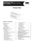
OPERATO S MANUAL
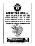
MARINE GASOLINE GENERATORS
22.5 SBEG and· SBEGA - &o~H:z
18.7 SBEG and SBEGA - 50Hz
20.0 SBEG and SBEGA - 60Hz
16.0 SBEG and SBEGA - 5·0Hz
Single and
CALIFORNIA PROPOSITION 65
WARNING
Exhaust gas from diesel and
gasoline engines (and some of
its constituents) are known to
the State of California to cause
cancer, birth defects, and other
reproductive harm.
A WARNING:
Exhaust gasses contain Carbon Monoxide, an odorless and
colorless gas. Carbon Monoxide is poisonous and can cause
unconsciousness and death. Symptoms of Carbon Monoxide
exposure can include:
• Throbbing in Temples
•Dizziness
• Muscular Twitching
•Nausea
• Vomiting
•Headache
• Weakness and Sleepiness •Inability to Think Coherently
IF YOU OR ANYONE ELSE EXPERIENCE ANY OF THESE SYMPTOMS,
GET OUT INTO THE FRESH AIR IMMEDIATELY. If symptoms persist,
seek medical attention. Shut down the unit and do not restart
until it has been inspected and repaired.
A WARNING DECAL is provided by WESTERBEKE and
should be fixed to a bulkhead near your engine or
generator.
WESTERBEKE also recommends installing CARBON
MONOXIDE DETECTORS in the living/sleeping quarters
of your vessel. They are inexpensive and easily
obtainable at your local marine store.
WARNING
Gone<alco;
Produce CAFIIlON MONOXIDE!j
Regular Mainlenanoe Aeqwed
·-
&/~'!~~
IlUI
--~
..
Gasoline with an ETHANOL content
higher than 10% (E10) is not allowed
and may void warranty.
Engines & Generators
SAFETY INSTRUCTIONS
INTRODUCTION
Read this safety manual carefully. Most accidents are
caused by failure to follow fundamental rules and
precautions. Know when dangerous conditions exist and
take the necessary precautions to protect yourself, your
personne~ and your machinery.
The following safety instructions are in compliance with
the American Boat and Yacht Council (ABYC) standards.
PREVENT ELECTRIC SHOCK
PREVENT BURNS - FIRE
A WARNING: Fire can cause injury or death!
•
Prevent flash fires. Do not smoke or permit flames or
sparks to occur near the throttle body, injector,
filter, fuel pump, or other potential sources of spilled fuel
or fuel vapors. Use a suitable container to catch all fuel
when removing the fuel lines, fuel filters, or other fuel
system components.
•
Do not operate with a Coast Guard Approved flame
arrester removed. Backfire can cause severe injury or
death.
Do not operate the engine with the air intake (silencer),
or flame arrester/filter screen removed.
A WARNING: Do not touch AC electrical connections
while engine is running. Lethal voltage is present at
these connections!
•
•
Shut off electrical power before accessing electrical
equipment.
Do not smoke or permit flames or sparks to occur near
the fuel system. Keep the compartment and the
engine/generator clean and free of debris to minimize the
chances of fire. Wipe up all spilled fuel and engine oil.
•
Be aware -
Use insulated mats whenever working on electrical
equipment.
PREVENT BURNS - EXPLOSION
•
Do not operate this machinery without electrical
enclosures and covers in place.
•
•
Make sure your clothing and skin are dry, not damp
(particularly shoes) when handling electrical equipment.
• Remove wristwatch and all jewelry when working on
electrical equipment.
• Do not: connect utility shore power to vessel's AC
circuits, except through a ship-to-shore double throw
transfer switch. Damage to vessel's AC generator may
result if this procedure is not followed.
•
• . Electrical shock results from handling a charged
capacitor. Discharge capacitor by shorting terminals
together.
A WARNING: Explosions from fuel vapors can cause
injury or death!
•
•
PREVENT BURNS - HOT ENGINE
A WARNING: Do not touch hot engine parts or
Do not fill the fuel tank(s) while the engine is running.
Shut off the fuel service valve at the engine when servicing
the fuel system. Take care in catching any fuel that might
spill. DO NOT allow any smoking, open flames, or other
sources of fire near the fuel system or engine when
servicing. Ensure proper ventilation exists when servicing
the fuel system.
•
•
•
Do not alter or modify the fuel system.
Be sure all fuel supplies have a positive shutoff valve.
Be certain fuel line fittings are adequately tightened and
free of leaks.
Make sure a fire extinguisher is installed nearby and is
properly maintained. Be familiar with its proper use.
Extinguishers rated ABC by the NFPA are appropriate
for all applications encountered in this environment.
Always check the engine coolant level at the coolant
recovery tank.
A WARNING: Steam can cause injury or death!
•
In case of an engine overheat, allow the engine to cool
before touching the engine or checking the coolant.
Follow re-fueling safety instructions. Keep the vessel's
hatches closed when fueling. Open and ventilate cabin after
fueling. Check below for fumes/vapor before running the
blower. Run the blower for four minutes before starting
your engine.
All fuel vapors are highly explosive. Use extreme care
when handling and storing fuels. Store fuel in a
well-ventilated area away from spark-producing
equipment and out of the reach of children.
•
•
exhaust system components. A running engine gets
very hot!
•
gasoline is highly flammable.
•
SAFETY INSTRUCTIONS
ACCIDENTAL STARTING
A WARNING: Carbon monoxide (CO} is a deadly gas!
A WARNING: Accidental starting can cause injury
or death!
•
To prevent accidential starting when servicing the generator, tum OFF the DC breaker or remove the 8 amp fuse
from the generators control panel.
•
To prevent accidential starting of the generator~
when servicing, tum the battery selector switch to the
OFF position.
•
Make certain all personnel are clear of the engine before
starting.
•
Make certain all covers, guards, and hatches are
re-installed before starting the engine.
•
Ensure that the exhaust system is adequate to expel gases
discharged from the engine. Check the exhaust system
regularly for leaks and make sure the exhaust manifolds
are securely attached and no warping exists. Pay close
attention to the manifold, water injection elbow, and,
exhaust pipe fittings.
•
Be sure the unit and its surroundings are well ventilated.
•
In addition to routine inspection of the exhaust system,
install a carbon monoxide detector. Consult your boat
, builder or dealer for installation of approved detectors.
•
BAnERY EXPLOSION
·A WARNING: Carbon monoxide (CO} Is an invisible
odorless gas. Inhalation produces flu-like symptoms,
nausea or death!
A WARNING: Battery explosion can cause injury
or death!
•
•
For additional information, refer to ABYC HT-22
(educational information on Carbon Monoxide).
Do not smoke or allow an open flame near the battery
being serviced. Lead acid batteries emit hydrogen, a
highly explosive gas, which can be ignited by elect:ical
arcing or by lit tobacco products. Shut off all electncal
equipment in the vicinity to prevent electrical arcing ·
during servicing.
Never connect the negative(-) battery cable to the
positive (+) connection terminal of the starter solenoid.
Do not test the battery condition by shorting the terminals
together. Sparks could ignite battery gases or fuel vapors.
Ventilate any compartment containing batteries to prevent
accumulation of explosive gases. To avoid sparks, do not
disturb the battery charger connections while the battery
is ·being charged.
•
Avoid contacting the terminals with tools, etc., to prevent
bums or sparks that could cause an explosion. Remove
wristwatch, rings, and any other jewelry before handling
the battery.
•
Always tum the battery charger off before disconnecting
the battery connections. Remove the negative lead first
and reconnect it last when disconnecting the battery.
•
Do not use copper tubing in exhaust systems. Exhaust
sulfur causes rapid deterioration of copper tubing
resulting in exhaust/water leakage.
•
Do not install exhaust outlet where exhaust can be drawn
through portholes, vents, or air conditioners. If the engine
exhaust discharge outlet is near the waterline. water could
enter the exhaust discharge outlet and close or restrict the
flow of exhaust. Avoid overloading the craft.
•
Carbon monoxide gas is present in exhaust fumes. Some
of the symptoms or signs of carbon monoxide inhalation
or poisoning are:
Vomiting
Muscular twitching
Dizziness
Intense headache
Throbbing in temples
Weakness and sleepiness
AVOID MOVING PARTS
A WARNING:.Rotating parts can cause injury
or death!
•
BAnERYACID
A WARNING: Sulfuric acid in batteries can cause
Do not service the engine while it is running. If a
situation arises in which it is absolutely necessary to
make operating adjustments, use extreme care to avoid
touching moving parts and hot exhaust system
components.
severe InJury or death!
•
When servicing the battery or checking the electrolyte
level, wear rubber gloves, a rubber apron, and eye
protection. Batteries contain sulfuri~ acid, whi:h is
.
destructive. If it comes in contact with your skin, wash It
off at once with water. Acid may splash on the skin or
into the eyes inadvertently when removing electrolyte
caps.
Engines & Generators
ii
SAFETY INSTRUCTIONS
• Do not wear loose clothing or jewelry when servicing
equipment; tie back long hair and avoid wearing loose
jackets, shirts, sleeves, rings, necklaces or bracelets that
could be caught in moving parts.
• Make sure all attaching hardware is properly tightened.
Keep protective shields and guards in their respective
places at all times.
• Do not check fluid levels or the drive belt's tension while
the engine is operating.
• Do not allow any swimming or activity around or near
the exhaust discharge opening for the generator while the
generator is operating. Carbon Monoxide poisoning or
death can occur.
ABYC, NFPA AND USCG PUBLICATIONS FOR
INSTALLING ENGINES AND GENERATORS
Read the following ABYC, NFPA and USCG publications
for safety codes and standards. Follow their recommendations.when installing your engine.
ABYC (American Boat and Yacht Council)
"Standards and Technical Information Reports for Small
Craft"
Order from:
ABYC
613 Third Street, Suite 10
Apriapolis, MD 21403
www.abycinc.org
NFPA - No.302 (National Fire Protection Association)
"Pleasure and Commercial Motor Craft"
Order from:
National Fire Protection Association
Battery March Park
Quincy, MA 02269
USCG (Umted States Coast Guard)
"regulatedions are under titles CFR33 and CFR46 of the
Code of Regulations"
Order from:
U.S. Government Printing Office
Washington, D.C. 20404
HAZARDOUS NOISE
A WARNING: High noise levels can cause hearing
loss!
• Never operate an engine without its muffler installed.
• Do not run the engine with the air intake (silencer) or
flame arrester removed.
• Do not run engines for long periods with their enclosures
open (when installed).
A WARNING: Do not work on machinery when you are
mentally or physically Incapacitated by fatigue!
OPERATORS MANUAL
Many of the preceding safety tips and warnings are repeated
in your Operators Manual along with other cautions and
notes to highlight critical information. Read your manual
carefully, maintain your equipment, and follow all safety
procedures.
GASOLINE ENGINE AND GENERATOR INSTALLATIONS
Preparations to install a gasoline engine or generator should
begin with a thorough examination of the American Boat and
Yacht Council's (ABYC) standards. These standards are from
a combination of sources including the USCG and the NFPA.
Sections of the ABYC standards of particular interest are:
H-2 Ventilation for Boats using Gasoline
· H-24 Gasoline Fuel Systems
P-1 Installation of Exhaust Systems
for Propulsion and Auxiliary Engines
P-4 .Marine Inboard Engines and Transmissions
EllAC and DC Electrical Systems on Boats
All installations must comply with the Federal Code of
Regulations (FCR).
www.abycinc.org
...
Ill
INSTALLATION
When installing WESTERBEKE engines and generators it is important that strict
attention be paid to the following information:
CODES AND REGULATIONS
Strict federal regulations, ABYC guidelines, and safety codes must be complied with
when installing engines and generators in a marine environment.
SIPHON-BREAK
For installations where the exhaust manifold/water injected.eXhaust elbow is close to
or will be below the vessel's waterline, provisions mu~t be made to install a siphonbreak in the raw water supply hose to the exhaust elbow. This hose must be looped a
minimum of 20" above the vessel's waterline. Failure to use a siphon-break when
the exhaust manifold/water injected exhaust elbow is near or below the loaded
water line of the vessel will result in raw water damage to the engine and possible
flooding of the vessel.
If you have any doubt about the position of the water-injected exhaust elbow relative
to the vessel's waterline under the vessel's various operating conditions, install a
siphon-break.
NOTE: A siphon-break requires periodic inspection and cleaning to ensure proper
operation. Failure to properly maintain a siphon-break can result in catastrophic
engine damage. Consult the siphon-break manufacturer for proper maintenance.
EXHAUST SYSTEM
The exhaust system's hose MUST be certified for marine use. Conugated Mmine
Exhaust Hose is recommended. The use of this type of hose allows for extreme bends
and tums without the need of additiinal fitting and clamps to accomplish these bends
and tums .In this regard, a single length of conugated exhaust hose can be used. The
system MUST be designed to prevent the entry of water into the exhaust system
under any sea conditions and at any angle of vessels heal.
A detailed Marine Installation Manual covering gasoline and diesel
engines and generators is supplied with every unit sold. This manual
.is also available in pdf format on our website to download
Website: www.westerbeke.com
.
IV
AVAILABLE FROM
YOUR WESTERBEKE
DEALER
SIPHON-BREAK WITH STAINLESS
LOOP FOR 1" HOSE
PART NO. 044010
INSTALLATION
EMISSION-RELATED INSTALLATION INSTRUCTIONS
"Failing to follow these instructions when installing a certified engine in a piece of non road
equipment violates federallilw (40 CFR 1068.105(b)), subject to fines or other penalties as described
in the Clean Air Act."
If your product is equipped with OBD (on board diagnostics) go to www.WESTERBEKE.COM and follow
the free interface software download instructions specific to your engine to obtain and install the
appropriate diagnostic software. The following is a list of OBD compliant products:
20.0 SBEGA
22.5 SBEGA
REFER TO THE DATA LOGGING PAGES IN THIS MANUAL.
To sample exhaust emissions on installed OBD compliant generators, gain access to the exhaust stream by
removing the test port plug on the exhaust elbow. Be sure to reinstall the plug securely when testing is
complete.
The Westerbeke generator that you purchased is certified fot constant-speed operation only. The use
of any Westerbeke product in any manner inconsistent with its intended use could be a violation of
Federal Law.
"If you install the engine in a way that mal{cs the engine's emission control information label hard to
read during normal engine maintenance, you must place a duplicate label on the equipment, as
del!cribed in 40 CFR 1068.105". Contact the factory for an additional engine emission control
information label if needed to comply with this rule.
To comply with 40 CFR 1048.105 (a) "Fuel line permeation. For nonmetallic fuel lines, you must
specify and use products that meet the Category 1 specifications for permeation in SAE J2260
(incorporated by reference in §1048.810)."
To comply with 40 CFR 1048.105 (c) "Diurnal emissions. Evaporative hydrocarbon emissions may
not exceed 0.2 grams per gallon of fuel tank capacity when measured using the test procedures
specified in §1048.501. Diurnal emission controls must continue to function during engine operation."
To comply with 40 CFR 1048.105 (d) "Running loss. Liquid fuel in the fuel tank may not reach
boiling during continuous engine operation in the final installation at an ambient temperature of 30
°C. Note that gasoline with a Reid vapor pressure of 62 kPa (9 psi) begins to boil at about 53 °C at
atmospheric pressure, and at about 60 °C for fuel tanks that hold pressure as described in
§1048.245(e)(1 )(i)".
To comply with 40 CFR 1048.245 (1) (i) "Use a tethered or self-closing gas cap on a fuel tank that
stays sealed up to a positive pressure of24.51\Pa (3.5 psi); however, they may contain air inlets that
open when there is a vacuum pressure inside the tank. Nonmetal fuel tanks must also use one of the
qualifying designs for controlling permeation emissions specified in 40 CFR 1060.240."
v
CARBON MONOXIDE "CO"I SAFE-CO GENERATORS
IMPORTANT INFORMATION
DESCRIPTION
Carbon monoxide "CO" is a component of engine exhaust. It
is a colorless, tasteless, odorless, lighter than air poisonous
gas that can kill you without any warning. CO poisoning is
one of the major safety risks associated with boating. It is a
threat that must not be underestimated.
Several standards for CO have been published, expressed in
parts per million "ppm" and hours of exposure:
Regulator
EPA
ACGIH
EPA
NIOSH
OSHA
ACGIH
NIOSH
NIOSH
(IDLH)
CO ppm
Exposure Hours
9
8
25
35
35
50
125
200
1200
8
1
8
8
0.5
0.0
0.0
1200 ppm is the so-called IDLH concentration·
IMMEDIATELY DANGEROUS TO LIFE AND HEALTH.
A city in California characterizes the effect of CO
concentration this way:
Parts per Million
25
100
200
Responses
Permissible exposure level, no
apparent toxic symptoms.
No poisoning for long period.
AUowable for several hours.
Should not be exposed above
this level for any period of
time. A possible mild frontal
headache in two to three hours.
As soon as CO leaves the exhaust outlet, the level is subject
to dilution in the open air. The closer a person is to the
exhaust outlet, the higher the concentration of CO.
In a closed space, such as the engine compartment
or underneath a stem swim platform, concentrations will
potentially rise to the undiluted level emanating from the
exhaust system due to a lack of fresh air to dilute the exhaust
gas. Therefore, one should never rely on dilution of the
exhaust to provide a margin of safety.
Westerbeke Safe-CO generators achieve reduction of CO
by precise control control of the engine's air/fuel ration
coupled with after treatment in a special catalyst. CO
emissions are not the same for every model because each
engine is different. Also, certain fuel system components are
commonized across several engine models being adequate
for some and extra-adequate for others, thus producing
different CO levels for different models.
The fuel system which accomplishes the required precise
air/fuel.ratio control is comprised of many different
components: purchased sub-assemblies, machined castings,
sensors, electronics and others. Because of the extreme level
of CO reduction, any variability in the functioning of any
these components can and will cause variability of the CO
output.
CO concentration also varies with load. Usually, but not
always, the worst case CO concentration occurs at maximum
load.
Even though Westerbeke Safe-CO generators are designed to
reduce normal levels of CO in the engine exhaust by approximately 99%, an exhaust leak of untreated exhaust would be
extremely dangerous. For this reason it is extremely important to install a CO detector ne(.lf the generator and to be sure
it is always turned on and functioning properly. If this detector sounds, do not tum it off, assuming it is a false signal.
You can not taste, smell, or otherwise detect CO. Leave the
detector on, tum off all engines and generators, evacuate the
boat leaving ports and hatches open, and seek professional
help.
Engines & Generators
vi
CARBON MONOXIDE "CO"/ LOW·CO GENERATORS
IMPORTANT INFORMATION
Catalyst performance will degrade over time. As the
generator accumulates operating hours, CO concentrations
will increase. The catalyst must be replaced every 2,000
hours of engine operation.
Verification of satisfactory CO levels must be done
seasonally or each 1,000 hours (which ever occurs first).
Verification involves actual sampling of exhaust gas with an
appropriate CO analyzer.
There are two locations where exhaust gas can be sampled.
Dry, but hot, exhaust can be sampled at the plugged tapped
hole in the exhaust elbow intended for back pressure
measurements. Measurements at this location may not be
practical in all instances due' to the high exhaust temperature,
temperature limits of the analyzer, safety concerns over
temperatures involved or the possibility of high levels of CO.
The other location, is the boat's exhaust outlet, which
contains entrained cooling water (except dry stack exhaust
systems). Only analyzers with probes should be used at this
location and it is critical that the probe not ingest water.
Probe-type analyzers have an air pump drawing a gas sample
through the probe. As a result, they tend to ingest water when
it is present. Be sure to aim the probe downwards with the
opening pointed in the direction of the water flow and just
out of the flow. Position the analyzer as high as possible with
the tubing leading to the probe running continuously downhill. Observe the usually translucent tubing between the
probe and the analyzer and be sure no,water is being
ingested. If any water is ingested into the analyzer, it must be
repaired or replaced and recalibrated.
Whenever taking the time to verify proper CO concentration
from the exhaust with a CO analyzer, always take the
opportunity to use the analyzer to "sniff' around the engine
looking for CO from exhaust leaks. Pay close attention to the
connection of the cylinder head to the exhaust manifold, the
exhaust manifold to_the water injected exhaust elbow, and all
- subsequent downstream exhaust components and hoses.
- Remember, exhaust gas that has not yet passed through the
catalyst is raw, untreated exhaust and is very high in Cd
content.
Analyzers usually require periodic calibration. Follow the
instructions that come with the analyzer very carefully
regarding calibration.
The following are manufacturers that offer CO analyzers:
Extech, TIF, Testa, TSI, Bacharach, Fluke, Monoxor, Pyrite,
Zellwgwer Analytics, Industrial Scientific Corp, GFG, TPI,
Teledyne and others. Westerbeke recommends analyzers with
a probe connected to the analyzer by a length of transparent
tubing. They are slightly more expensive than those with the
sensor built into one end of the analyzer, but they allow you
to sample the exhaust coming out of the boat's exhaust outlet.
D Refer to MEASURING BACK PRESSURE, CO SENSORS ,and
EXHAUST SYSTEM MAINTAINANCE., in the back pages of
this manual.
When measuring CO at the exhaust outlet be aware of the
ambient CO level by also measuring CO away from and
upwind of the exhaust outlet, especially in marinas. the CO
level at tqe exhaust will be influenced upwards by the
ambient level.
Engines & Generators
vii
EMISSIONS
This genset meets the requirements of California's Exhaust
Emissions Standards as stated on the nameplate.
California users of this genset should be aware that
unauthorized modifications or replacement of fuel, exhaust,
air intake, or speed control system components that affect
engine emissions are prohibited. Unauthorized modification,
removal or replacement of the engine label is prohibited.
Federal Emissions Compliance Period: The Federal
Emissions Compliance Period referred to on the nameplate
indicates the number of operating hours for which the engine
has been shown to meet Federal Emissions requirements.
Catagory C== 250 hrs, B==500 hrs,m A =lOOO.hrs.
You should carefully review the Operators Manual and
Installation Manual and any other information you receive
with your genset. If you are unsure that the installation, use,
maintenance, or service of your genset is authorized, you
should seek approval from your WESTERBEKE dealer.
California genset users may use the table below as an aid in
locating information related to the California Air Resources
Board requirements for emissions control.
EMISSIONS CONTROL INFORMATION TABLE
Emissions Warranty Information
The California emissions control warranty statement is located in the same
packet, if information as this manual when the genset is shipped from the
factory.
Engine Fuel Requirements
The engine is certified to operate on unleaded gasoline. See FUEL
RECOMMENDATIONS.
Engine Valve Adjustment
See MAINTENANCE SCHEDULE.
Engine Ignition Timing
See MAINTENANCE SCHEDULE.
Engine Lubricating-Oil Requirements
See ENGINE OIL RECOMMENDATIONS.
Engine Adjustments
ECU.
Engine Emission Contol System
.The engine emission control system consists of engine design and precision
manufacture.
Catalyst
See MAINTENANCE SCHEDULE.
Oxygen Sensor
See MAINTENANCE SCHEDULE.
Back Pressure
See MAINTENANCE SCHEDULE.
/"W'/WESTERBEKE
l Engines & Generators
viii
TABLE OF CONTENTS
Safety and Emissions Data ....................................v-vm
20KW SBEG/22.5KW SBEG Parts Identification .......... 2
Introduction ....................................................................3,4
Fuel, Engine Oil and Engine Coolant.. .......................... 5
Preparations for Initial Start·Up ...................................6
Operating Instructions.....................................................7
Stop/Start Procedure ..................................................... 7
Remote Panel/Wiring ................................................... 7
Break·ln Procedure/Daily Operation ............................. 8
Safety Shutdown Sensors/Switches .............................. 9
Maintenance Schedule .................................................. 10
Cooling System ............................................................... 12
Changing .CC>olant.. ..................................................... 12
Thermostat .................................................................. 13
Zinc Anode ................................................................. 13
Heat Exchanger .......................................................... 13
Raw Water Intake Strainer ......................................... 14
Raw Water Pump ........................................................ l4
Fuel System ..................................................................... 15
Gasoline/Water Separator and Filter .......................... 15
Engine Fuel Filter ....................................................... 15
Bleeding the Fuel System .......................................... 16
Electronic Fuel Injection (EFI) .................................. 17
Engine Lubrication Oil ................................................... 18
Changing the Engine Oil... ......................................... 18
Replacing the Oil Filter .............................................. 18
Oil Pressure ..................................................................... 19
Testing Oil pressure .................................................... f9
Timing Belt Inspection/Installation ............................ 20
Engine Adjustments .......................................................22
Spark Plugs ................................................................. 22
Drive Belt Adjustment ............................................... 22
Valve Clearance Adjustment ...................................... 23
Ignition timing ............................................................ 23
Torquing the Cylinder Head Bolts ............................. 23
Electronic Fuel Injection ..............................................24
Starter Motor ...................................................................26
Testing ........................................................................ 26
Alternator Testing .......................................................... 27
Alternator! Testing ...................................................... 28
Battery Care ............................................................... 29
Wiring Diagrams ............................................................30
Engine Troubleshooting (Chart) ...................................34
Electrical Troubleshooting (Chart) .............................. 36
Software/Data Logging ..................................................37
SBEG Troubleshooting ....................................................31
Generator Information .................................................. .41
SBEG • Single/Three Phase ...........................................42
Voltage Regulator Adjllstments .................................. .43
AC VoHage Connections ...............................................44
AC Voltage Connections/Three Phase ...................... .45
SBEG Troubleshooting (Chart) ......................................47
Internal Wiring· Diagrams ..............................................48
Shore Power Transfer Switch .......................................49
Engine/Generator Speciflcations ................................ .so
Lay•Up and Recommissioning.............. .. .................... 52
Measuring Exhaust·sack·Pressure .............................53
Exhaust System Maintenance ......................................54
Remote Oil Filter Assembly ..........................................55
Torque Speclflcations ....................................................56
Metric Conversions ........................................................57
Suggested Spare Parts ..................................................58
20KW SBEG/22.5KW SBEG PARTS IDENTIFICATION
SCHRADER VALVE
FUEL PRESSURE REGULATOR.
CAP
ELECTRONIC FUEL
COOLANT FILL
AIR TEMP
INJECTOR (EFI)
PRESSURE CAP)
SENSOR -...____--
OXYGEN
SENSOR
(WB)
OXYGEN SENSOR
(NB)
. ZINC
ANODE
ISOLATOR MOUNT
FRONT
DC ALTERNATOR
HEAT
EXCHANGER
DISCHARGE
SYPHON BREAK
CONNECTION
COOLANT FILL
COIL/BALLAST {MANIFOLD PRESSURE
REGISTER
· CAP)
OXYGEN SENSOR
n:.!M..-----AIR TEMPERATURE
SENSOR
h\""111~--THERMDSTAT ASSEMBLY
CONTROL PANEL
OIL PRESSURE
lllri'-----SENSOR
RAW WATER
PUMP
EMERGENCY
STOP SWITCH
(DC BREAKER)
REAR
fUEL COOLER
IN·LET FUEL FILTER
RIGHT·SIOE
Engines & Generators
2
INTRODUCTION
WESTERBEKE customers should also keep in mind the
timtt span between printings of WESTERBEKE product
software and the unavoidable existence of earlier
WESTERBEKE manuals. In summation, product software
provided with WESTERBEKE products, whether from
WESTERBEKE or other suppliers, must not and cannot
be relied upon exclusively !18 the definitive authority on
the respective product. It not only makes good sense
but is imperative that appropriate representatives of
WESTERBEKE or the supplier in question be consulted
to determine the accuracy and currentness of the
product software being consulted by the customer.
This WESTERBEKE Generator is a product of
WESTERBEKE's long years of experience and advanced
technology. We take great pride in the superior durability and
dependable performance of our engines and generators.
Thank you for selecting WESTERBEKE.
In order to get the full use and benefit from your generator, it
is important that you operate and maintain it correctly. This
manual is designed to help you do this. Please read this
manual carefully and observe all the safety precautions
throughout. Should your generator require servicing, contact
your nearest WESTERBEKE dealer for assistance.
This is your Operators Manual. A Parts Drawing is also
provided and a Service Manual is available from your
WESTERBEKE dealer. If you are planning to install this
equipment yourself, contact your WESTERBEKE dealer for
WESTERBEKE'S Installation Manual.
SERIAL NUMBER LOCATION
The generator serial number and model number are located
on a decal on the generator housing. Take the time to enter
the information on the blank decal provided below as this
will provide a quick reference when seeking technical information and/or ordering repair parts.
WARRANTY PROCEDURES
~~~~~~P-1~
. 50 HZ. 60
Your WESTERBEKE Warranty is in~;luded in a separate
folder. If you have not received a customer identification
card registering your warranty 60 days after submitting the
warranty registry form, please contact the factory in
writing with model information, including the unit's serial
number and commission date.
.
MODEL---~----
RPM·--------~-
KVI ___________ _
1..,.,1WESTERBEKE
I
.
KVA -----------
Engines & Generators
VOLTS-~~ .• ·--Customer Identification
WESTERBEKE OWNER
AMPS--··,----ENG. HP ------ENG. SER. NO.
MAIN STREET
HOMETOWN, USA
Model
GEN. SER. NO.
Ser. #
PF/PHASE ----
Expires
I
WIRES _____ ---RATING _______ _
PRODUCT SOFTWARE
Product software, (tech data, parts lists, manuals, brochures
and catalogs), provided from sources other than
WESTERBEKE are not within WESTERBEKE'S
CONTROL.
INSUL CLASS __
TEMP. RISE---BATIERY ------
C.t.O. ---------Fill in the information for your reference.
~
l!iiiO~iiiii~jiii!iii~iiijiji#fiiii;iiiiiliiii=Jjjiii$fiiii~iiii.~~o
Engine I.D. Plate
Engines & Generators
3
INTRODUCTION
ORDERING PARTS
PROTECTING YOUR INVESTMENT
Whenever replacement parts are needed, always provide the
generator and engine model and serial numbers. In addition,
include a complete part description and part number for each
part needed, see the separately furnished Parts Drawing.
Also insist upon WESTERBEKE packaged parts because
will fit or generic parts are frequently not made to the same
specifications as original equipment.
Care at the factory during assembly and thorough testing
have resulted in a WESTERBEKE generator capable of
many thousands of hours of dependable service. However the
manufacturer cannot control how or where the generator is
installed in the vessel or the manner in which the unit is
operated and serviced in the field. This is up to the
buyer/owner-operator.
NOTES, CAUTIONS AND WARNINGS
NOTE: Six important steps to ensure long generator life:
As this manual takes you through the operating procedures,
maintenance schedules, and troubleshooting of your
generator, critical information will be highlighted by
NOTES, CAUTIONS, and WARNINGS. An explanation
follows:
• Proper engine and generator installation and alignment.
• An efficient well-designed exhaust system that includes
an anti-siphon break to prevent water from entering the
engine.
• Changing the engine oil and oil filters every IOO
operating hours.
NOTE: An operating procedure essential to note.
A
• Proper maintenance of all engine and generator
components according to the maintenance schedule in
this manual.
CAUTION: Procedures, which if not strictly
observed, can result in the damage or destruction of
the engine or generator.
• Use clean, filtered unleaded fuel.
• Winterize your engine according to the LAY-UP AND
RECOMMISSIONING section in this manual.
A
WARNING: Procedures, which if not properly
followed, can result in personal injury or loss of life.
DIAGNOSTIC SOFTWARE
A Diagnostic Software Kit #05541 0 is available for purchase
from your Westerbeke Distributor. The kit contains discs
having Diagnostic Software EClO, CEC10,0BD1;EC20 and
ECll. Also in this kit is an Interface Cable to connect
between the unit's ECU and your laptop.
NOTE: A carbon monoxide warning decal has been provided
by WESTERBEKE. Affix this decal in a visible location in the
engine room.
SPARES AND ACCESSORIES
The software discs cover all our Low CO models, D-NET
and Multi-Port models. The software is an important tool
to use in monitoring system operation and in diadnosis of
operating issues,
Certain spare parts will be needed to support and maintain
your WESTERBEKE generator or engine when cruising (see
SUGGESTED SPARE PARTS). Often even simple items such
as proper fuel and oil filters can be difficult to obtain along
the way. WESTERBEKE will provide you with a suggested
spares and accessories brochure to assist you in preparing an
on-board inventory of the proper WESTERBEKE parts.
With some models, the software is needed to change Hertz
operation of the engine and AC voltage output readings on
the LCD Display in conjunction with AC voltage output
changes in the field.
UNDERSTANDING THE GASOLINE ENGINE
INSTALLATION MANUAL
The gasoline engine driving an AC generator is in many
ways similar to a gasoline automobile engine. The cylinders
are verticle in-line, and the engine's cylinder head has an
overhead camshaft which is chain-driven.The engine utilizes
a solid-state distributor which is horizontally mounted and
camshaft driven. The engine incorporates a pressure type
lubrication system, and a fresh water-cooled engine block
which is thermostatically controlled. To a large degree, the
generator's engine requires the same preventive maintenance
that is required of a gasoline automobile engine. The most
important factors to the generator's longevity are proper
ventilation, maintenance of the fuel system, ignition system,
and cooling system and generator back-end.
Publication #043268 provides detailed information for
installing generators.
CARBON MONOXIDE DETECTOR
WESTERBEKE recommends mounting a carbon monoxide
detector in the vessels living quarters. Carbon monoxide,
even in small amounts, is deadly.
The presence of carbon monoxide indicated an exhaust leak
from the engine or generator or from the exhaust
elbow/exhaust hose, or the fumes from a nearby vessel are
entering your boat.
If carbon monoxide is present, ventilate the area with clean
air and correct the problem immediately!
Engines & Generators
4
FUEL, ENGINE OIL AND ENGINE COOLANT
GASOLINE
ENGINE COOLANT
WESTERBEKE recommends a mixture of 50% antifreeze and
50% distilled water. Distilled water is free from the chemicals
that can corrode internal engine surfaces.
A
CAUTION: Use unleaded 89 Octane gasoline or
higher. Ethanol gasoline must not exceed E10 (10%).
Gasoline with higher percentages of Ethanol are not
acceptable for use in these models and can void the
warranty.
The antifreeze performs double duty. It allows the engine
to run at proper temperatures by transferring heat away from
the engine to the coolant. It also lubricates and protects the
cooling circuit from rust and corrosion. Use a good quality
antifreeze that contains supplemental cooling additives (SCAs)
that keep the antifreeze chemically balanced, crucial to long
term protection.
Gasoline with an ETHANOL content
higher than 10% (E10) is not allowed
and may void warranty.
The water and antifreeze should be premixed before being
poured into the cooling circuit. WESTERBEKE recommends
Prestone (pre-mixed)
NOTE: Use the new environmentally-friendly, long lasting,
antifreeze that is now available.
When fueling, follow U.S. Coast Guard procedures, closing
hatches and companionways to prevent fumes from entering
the boat and cabins. Be sure to ventilate after fueling.
A proper 50/50 mixture as recommended will protect the
engine coolant to temperatures of -40°F.
Care Of The Fuel Supply
COOLANT RECOVERY TANK
Use only clean fuel! The clearance of the components in
your fuel injection pump is very critical; invisible dirt
particles which might pass through the filter can damage
these finely finished parts. It is important to buy clean fuel,
and keep it clean. The best fuel can be rendered
unsatisfactory by careless handling or improper storage
facilities. To assure that the fuel going into the tank for your
engine's daily use ·is clean and pure, the following practice is
advisable:
A coolant recovery tank kit is supplied with each generator.
The purpose of this recovery tank is to allow for engine
coolant expansion and contraction during engine operation.
Some loss of coolant may occur as a result of evaporation
and the effects of exhaust manifold working temperature.
NOTE: This tank, with its short run of plastic hose, is best
located at or above the level of the engine :S manifold.
\
\(
Purchase a well-known brand of fuel.
Install and regularly service a good, Coast Guard approved
metal bowl type filter/water separator between the fuel tank
and the engine.
ENGINE OIL
Use a heavy duty engine oil with an API classification of SJ,
SL, SM or SN. Change the engine oil and filter after an
initial 50 hours of engine break-in operation. Then follow
the oil and filter change intervals as specified in the
MAINTENANCE SCHEDULE in this manual.
An oil viscosity of SAE 15W-40 or SAE lOW-40 is
recommended for this engine in all conditions and all
seasons.
Westerbeke Corporation does not approve or disapprove the
use of synthetic oils. If synthetic oils are used, engine breakin must be performed using conventional oil. Oil change
intervals must be as listed in the MAINTENANCE
SCHEDULE section of this manual and not be extended if
synthetic oils are used.
NOTE: The information above supersedes all previous
statements regarding synthetic oil.
NOTE: The engine compartment should have a gasoline fume
detector/alarm properly installed and working.
Engines & Generators
5
PREPARATIONS FOR INITIAL START-UP
PLASTIC COOLANT
RECOVERY TANK
MANIFOlD PRESSURE CAP
R BLEED
PETCOCK
)
THIS LINE RETURNS
COOLANT TO THE ENGINE
PRESTART INSPECTION
OIL DIPSTICK
EXHAUST MANIFOLD
Before starting your generator for the first time or after a
prolonged layoff, check the following items:
• Visually examine the unit. Look for loose or missing
parts, disconnected wires, unattacred hoses, and check
threaded c~nnections. Search for any gasoline leaks.
• Check the engine oil level: add oil to maintain the level at
the full mark on the dipstick.
• Check load leads for correct connections as specified in
the wiring diagrams.
• Check the fuel supply and examine the fuel filter/separator
bowls for contaminants.
• Be sure no other generator or utility power is connected to
the load lines.
• Check the DC electrical system. Inspect wire connections
and battery cable connections.
• Be sure that in power systems with a neutral line that the
neutral is properly grounded (or ungrounded) as the system
requires, and that generator neutral is properly connected
·to the load neutral. In single phase systems an incomplete
or open neutral can supply the wrong line-to-neutral
voltage on unbalanced loads.
NOTE: The starting battery must be totally dedicated to the
generator and maintained by the generator's DC charging
alternator and no other source.
• Check the coolant level in both the plastic recovery tank
and at the mani(old.
• Make certain the raw water thru-hull is open.
NOTE: After the initial running of the generator, the air in
the engine's cooling system will be purged to the coolant
recovery tank. Open the air bleed petcock to ensure that
the cooling system is purged of air. After shutdown and
after the engine has cooled, the coolant from the recovery
tank will be drawn into the engine's cooling system to
replace the purged air.
A
CAUTION: When starting the generator, it is
recommended that ai/.AC loads. especially large
motors•. be switched OFF until the engine has come
up to speed and. in cold climates. starts to warm up.
This precaution will prevent damage caused by
unanticipated operation of the AC machinery and will
prevent a cold engine from stalling.
Before subsequent operation of the generator, the engine's
manifold should be topped off and the coolant recovery
tank's level brought to 1/4 full.
Engines & Generators
6
CONTOL PANEL • START/STOP PROCEDURE
TO START: (DC CIRCUIT BREAKER ON)
Simply press the rocker switch to the start position and release
(the switch will revert to its center position) the engine will
START electronically. A GREEN LED on the switch will
indicate the engine is running.
NOTE: There is a few second delay while the ECU self-tests
before the start switch responds.
DC CIRCUIT BREAKER
TO STOP
Press the rocker switch to the STOP position and release.
The GREEN LED will go out indicating the engine has
shutdown.
CONTROL PANEL • OPERATING
GENERATOR CONTROL PANEL
The start/stop rocker switch is the only functional component
on the generator control panel used to start and stop the
generator.
The start/stop rocker switch is a three position switch with
momentary contacts in the (START) and (STOP) position and
a stationary contact function in the center (NORMAL). This
position allows the generator to run once started and also
enables the remote start/stop panel(s) to control the starth;;top
functions of the generator.
The (START) position starts the generator and once released
reverts to the center position. The (STOP) position stops the
engine in normal operation as well as in an emergency
situation. This position is also used to prime the fuel system
when necessary.
Failure to Start
The start cycle will automatically terminate after 6-8 seconds of
cranking. Three crank cycles can be attempted before the ECU
initiates a SPEED fault and prevents further crank cycle attempts.
Invistigate the cause of this no-start, correct it and reset the ECU.
OIL PRESSURE
ENG TEMP
Prolonged cranking can result in the exhaust filling with
water and backing into the engine.
The LED fault shut down display board has four separate LED
lights to display to the operator the cause of the generators
automatic shut down. The four LED displays are: low oil
pressure, high engine operating temperature, high exhaust
temperature and engine over-speed/under-speed (flashes).
Should the generator shut down from one of these faults, the fault
LED will remain illuminated. To reset the LED, the DC breaker
on the control box must be turned OFF and then back ON.
NOTE: The CHECK ENGINE LED (SBEGA Models only)
indicates a possible emissions control issue. Immediate
action should be taken to troubleshoot and correct this
problem.
OVER/UNDER
SPEED
EXH TEMP
The Ext Alarm indicates a faulty fire suppression circuit. By-pass
the circuit to determine the fault (the fire suppression circuit must
be closed whentl;te circuit is running).
The. 8 Amp Fuse protectS the Control Panel from High Ampeage
or Short Circuit
The 15 Amp DC Circuit Breaker protects the Kl, K2, K3
relays (closed circuit) ftom high amperage or short circuit.
Sometimes after servicing the fuel system or changing the fuel
filter, air can accumulate in the fuel line or the throttle body and
prevent starting. Schrader valves located on the high pressure
pump module and the fuel rail are used to remove this trapped
air. Refer to the BLEEDING THE FUEL SYSTEM in this manual.
Abnormal Stop
(Refer to the SAFETY SHUTDOWN SWITCHES)
7
REMOTE STOP/START PANEL
PN 049148
DESCRIPTION (with Fault Display)
0
A remote start/stop panel is available that allows for the
engine/generator to be contolled from any location on the
boat.
The remote panel connects to the main panel using an
extension harness (maximum length of 100' ). Once installed,
the engine/generator can be started and stopped from either
the remote or the main panel.
lV\T,f WESTERBEKE
3.94
D
Simply press the rocker switch to the to the START position
and release (the switch will revert to its center position) and
the engine will START electronically. A GREEN LED on
the switch will indicate the engine is running.
before the start switch responds.
Stopping
Press the rocker switch to the STOP position and release-.
The GREEN LED will go out indicating the erikine has
shut down.
T
STOP
Starting (DC CIRCUIT BREAKER ON)
NOTE: There is a few second delay while the ECU self-tests
0
0
Refer to page 7 (CONTROL PANEL START/STOP
PROCEDURE) for additional instructions and warnings.
REMOTE PANEL HARNESS: 15' Pn 049210
30' Pn 049211
50' Pn 049667
75' Pn 049668
Abnormal Stop
1oo· Pn 049669
(Refer to the SAFETY SHUTDOWN SWITCHES)
REMOTE STOP/START PANEL WIRING DIAGRAM
#18 ORG
#18 GRN
IJ
0
U.J
0:
"'..J
"'
rX
0
~
12 •
#18 WHT/BLK/REO
~u
@;
~ t;
II
Iii 0
#18 WHT/BLK/BLU
""
."'-
#20
ldJ
WHT/BLK/BRN
6
#20 WHT/BLK/YEL
r h
zQ} t--
®CD
O.P.
L-
I0
3 POSITION
STOP
T
) 't
#18 WHT/BLK/RED
1J
"6
I
>
.
"'-
#20 WHT/BLK/GRY
#20 WHT/BLK/GRN
RUN
INDICATOR
START
2
jo.S. [, T W. T.jo.P.,
T66
O.S.
f--'
SIDE
START/STOP sw.
CENTER OFF
~
E.T.
-0!4l(JJ
VI[WtO fROM WIR[
,n
W.T.
t
2
3
"-
~
0
r-
<(
0..
0..
</)
(/)
1-
w
w
0:
1-
"'
)-
V>
X
·o:
0:
V)
4
5
6
V>
a..
..J
0
Engines & Generators
7a
8
:>:
"'z
w
:::0:
X
w
9
"'w
w
"w
>
0
BREAK-IN PROCEDURE/THE DAILY OPERATION
NOTE: Some unstable running may occur in a cold engine.
BREAK-IN PROCEDURE
Thi~ condition should lessen as normal operating temperature
is reached and loads are applied.
After the generator has been started, check for proper
operation and then encourage a fast warm-up. Run the
generator between 20% and 60% of full-load for the first
10 hours.
A CAUTION: Do not operate the generator for long
periods of time without a load being placed on the
generator.
A CAUTION: Do not anempt to break-in your
generator by running without a load.
GENERATOR ADJUSTMENTS
After the first 10 hours of the generators operation, the load
can be increased to the full-load rated output, then
periodically vary the load.
Avoid overload at all times. An overload is signaled by
smoky exhaust with reduced output voltage and frequency.
Monitor the curr~nt being drawn from the generator and keep
it within the generators rating. Since the generator operates at
1800 rpm to produce 60 hertz or 1500 rpm for 50 hertz,
control of the generator's engine break-in is governed by the
current drawn from the generator.
Once the generator has been placed in operation, there may
be governor adjustments required for engine speed (hertz)
during the engine's break-in period (first 50 hours) or after
this period.See ENGINE SPEED (HERTZ) ADJUSTMENT
under ENGINE ADJUSTMENTS).
NOTE: After the first 50 hours of generator operation, check
the maintenance schedule for the 50 hour service check.
To protect against unintentional overloading of the generator,
the generator's output leads should be routed through a
circuit breaker that is rated at the rated output of the
generator.
NOTE: Be aware of motor starting loads and the high current
drawn required for starting motors. The starting amperage
drawn can be 3 to 5 times normal running amperage. See
GENERATOR INFORMATION in this manual.
CHECK LIST
Follow this check list each day before starting your generator.
• Record the hourmeter reading in your log (engine hours
relate to the maintenance schedule).
• Visually inspect the generator for fuel, oil, or water leaks.
• Check the oil level (dipstick).
• Check the coolant level in the coolant recovery tank.
• Check your fuel supply.
• Check the starting batteries (weekly).
• Check drive belts for wear and proper tension (weekly).
• Check for abnormal noise such as knocking, vibration and
blow-back sounds.
• Confirm exhaust smoke:
When the engine is cold- white smoke.
When the engine is warm - almost smokeless.
When the engine is overloaded - some black smoke.
8
SAFETY SHUTDOWN SENSORS AND SWITCHES
SAFETY SHUTDOWN SWITCH/SENSORS
Oil Pressure Sensor
The engine is protected by four automatic shutdown circuits.
Should a shutdown occur, do not attempt to restart without
finding and correcting the cause. Refer to the heading
Engine starts, runs and then shuts down in the ENGINE
TROUBLESHOOTING section of this manual.
An oil pressure sensor is located off the engines oil gallery.
Oil pressure on the sensor affects the DC voltage through tl1e
sensor to the ECU. Should the voltage reach a preset value,
the ECU will interpret this as a low oil pressure issue and
open the K2 run relay, stopping the generator. The oil
pressure LED on the panel will illuminate,
The following is a description of these automatic shutdown
circuits:
Water Temperature Sensor
A water temperature sensor is located at the thermostat
housing. This sensor sends a DC voltage to the ECU that it
interprets as engine antifreeze coolant temperature. Should
this voltage reach a set value, the ECU will interpret this as
high antifreeze coolant temperature and open the K2 run
relay, stopping the generator. The engine temp. LED on the panel
will then illuminate.
TEE FITTING
WITH 1/BNPT
ACCESS PLUG
OIL PRESSURE
SENSOR
Engine DC Circuit Breaker
The generator's engine DC circuit is protected by a rocker
type DC 20 amp breaker mounted on the control box. 77zis
also serves as an Emergency Stop Switch. Excessive DC
current draw or DC electrical overload anywhere in the
instrument panel wiring or engine wiring will cause the
breaker to trip to the OFF position. In this event, the DC
power to the ECU will be interrupted, stopping the generator.
No panel LED will illuminate. Check and repair the source
of the problem. After repairing the fault, reset the breaker and
restart the generator.
NOTE: Referto the GENERATOR IMFORMATION page for
a description of the of the AC CIRCUIT BREAKER.
High Exhaust Temperature Switch
High/Low RPM Shutdown
An exhaust temperature switch is located on the water
injected exhaust elbow. Normally closed, this switch will
open and the ECU will interpret this as a high exhaust
temperature and open the K2 run relay, stopping the
generator. The exhaust temperature LED on the panel will
illuminate. The switch opens at 260-270F (127-132C). This
switch resets (contacts close) at approximately 225F (107C).
The ECU monitors engine speed by the AC voltage
produced by the MPU. Should this voltage reach a preset
value, the ECU will interpret this as an overspeed (2175 rpm
approximately) and open the K2 relay, stopping the
generator. The panel overspeed LED will illuminate. Should
the MPU produce a low AC voltage that the ECU interprets
as an underspeed condition, the ECU will open the K2 relay
and stop the generator. The overspeed LED will then blink.
I'
HIGH. EXHAUST
TEMPERATURE SWITCH ·
MOUNTED ATTHE
EXHAUST ELBOW
9
MAINTENANCE SCHEDULE
A
WARNING: Never attempt to perform any service while the engine is running. Wear the proper safety equipment such as goggles
and gloves, and use the correct tools for each job. When servicing/replacing DC components, turn off the DC circuit breaker on the
control panel, or turn off the battery switch.
SCHEDULED MAINTENANCE
EXPLANATION OF SCHEDULED MAINTENANCE
I
DAILY CHECK BEFORE START-UP
Coolant Level
Check at recovery tank, if empty, check at manifold. Add coolant if needed.
Engine 011 Level
Oil level should indicate between MAX and LOW on dipstick. Do not overfill!
Fuel/Water Separator (owner iostalled)
Check for water and dirt in fuel. Drain filter if necessary. Replace filter every 250 operating
hours or once a year.
Fuel Supply
Fresh unleaded gasoline with an octane. rating of 89 or higher. Lower octane will affect
engine performance. 10% ethanol maximum.
*Visual Inspection of Engine
Check for fuel, oil and water and exhaust leaks. Check that the water injected exhaust elbow
securing v-clamp is tight. Insure there are no exhaust leaks around the elbow. Inspect wiring
and electrical connections. Look for loose bolts/hardware and possible corrosion.
Drive Belts
Inspect raw water pump-alternator belt and water pump belt drive. Adjust tension as needed,
then check monthly.
'INITIAL 50 HOURS OF OPERATION
*Spark Plugs
Clean/re-gap.
Engine Oil and Filler
Initial engine oil and filter change at 50 hours, then change both every 100 hours.
*Exhaust System
Initial check at 50 hours, then every 250 hours or once a year. Carefully inspect for leaks.
Check that the exhaust hoses are properly attached and that the securing clamps are tight.
Check the integrity/mounting security of the water injected exhaust elbow.
*Air Screen/Flame Arrestor
Remove, clean and re-install screen pack. Inspect rubber sealing ring and replace if
necessary, then once a year.
*Valve Adjustment
Check adjustment of valves. Check again at 500 hours.
*Inlet Fuel Filter
Initial change; then every 250 hours or once a year.
*Fuel Filler
Initial change, then every 250 hours or once a year.
*Cylinder Head Bolls
Re-torque (cold), no further re-torque required.
I
EVERY 50 OPERATING HOURS OR MONTHlY
*Drive Belts
(Fresh Water/Raw Water Pumps)
Starting Batteries
Inspect for proper tension (3/8' to 1/2" deflection) and adjust if needed. Check belt
for slipping, cracking and wear. Adjust tension or replace as needed. Replace cover.
Check electrolyte levels Make sure cables and connections are in good order. Clean
off corrosion if needed. Apply petroleum jelly to terminals for corrosion protection.
Electric Fuel Pump
Inspect for leaks, ensure fuel and electrical connections are clean and tight.
Inspect and clean zinc anode. Replace if necessary. Note the condition, then determine
your own inspection schedule.
Zinc Anode
I
EVERY 100 OPERATING HOURS OR YEARlY
Engine Oil and Filler
Change engine oil and filter.
*Air Screen/Flame Arrestor
Remove, clean and re-install screen pack. Inspect rubber sealing ring and replace if
necessary.
*WESTERBEKE recommends this service be performed by a knowledgeable mechanic.
Engines & Generators
10
MAINTENANCE SCHEDULE
NOTE: Use the engine hounneter to log your engine hours or record your engine hours nmning time.
SCHEDULED MAINTENANCE
EXPLANATION OF SCHEDULED MAINTENANCE
I
EVERY 250 OPERATING HOURS OR YEARLY
*Exhaust Elbow/Exhaust System
*Fuel Filler and 0-Rings
*Inlet Fuel Filler
*Generator
Check the structual integrity of the water injected exhaust elbow casting. Check the integrity
of the exhaust system attached to the elbow. All hose connections should be secure. No
chafing. No exhaust leaks. Hoses and muffler are in good serviceable condition.
NOTE: An exhaust leak will cause exposure to carbon monoxide!
Remove and replace fuel filter and all sealing a-rings.
Remove and replace inlet fuel filter.
---------''-------------------------Check that AC connections are clean and secure. Ensure wires have no chafing.
See GENERATOR INFORMATION.
*Hoses
Engine hoses should be firm and tight. Replace if hoses become spongy, brittle or
delaminated. Check and tighten all hose clamps as needed.
*Ignition Timing
Check timing and adjust as needed. ·
Vibration IsolatorS/Engine Mounts
Check vibration isolators, brackets and mounting hardware. Replace as needed.
*Heat Exchangl!r
Open heat exchanger end cap(s) and clean out debris.
Replace gasket and 0-rings if needed.
I
EVERY 5oo. OPERATING HOURS oR YEARLY
*Raw Water Pump
Remove the pump cover and inspect the pump assembly for wear, especially cam and wear
plates. Replace the impeller and gasket. Lubricate the impeller when re-assembling.
*Exhaust System Catalyst
Inspect for proper operation. Replace at 2000 operating hours.
IEVERY 500 OPERATING HOURS OR EVERY TWO YEARS
*Ignition Wires/Ignition System
Inspect for deterioration. Test resistance.
*Coolant System
Drain, flush and re-fill the cooling system with appropriate antifreeze mix. Replace the
thermostat and coolant pressure cap.
*Valve Clearances
. *Starter Motor
•co in Exhaust
Adjust valves. (incorrect valve clearance will result in poor engine performance.)
Check solenoid and motor for corrosion. Remove and lubricate. Clean and lubricate the starter
motor pinion drive
Test sample with CO analyzer.
EVERY 1000 OPERATING HOURS OR OR EVERY FIVE YEARS
*Heat Exchanger
Remove and replace the timing belt. NOTE: Failure to replace the timing belt at the
recommended interval could result in timing belt failure resulting in major damage
to the engine.
Remove the heat exchanger for professional cleaning and pressure testing.
*Diverter Valve
• Oxygen Sensor
Replace #054500).
Inspect.
*Engine Timing Belt
I
EVERY 2000 OPERATING HOURS
*Oxygen Sensor
* Exhaust System Catalyst
Test- see Service Manual, replace if needed.
Remove and replace exhaust catalyst.
A WARNING: Never attempt to perform any service while the engine is running. Wear the proper safety equipment
such as goggles and gloves, and use the correct tools for each job. When servicing/rep/acing DC components, turn off
the DC circuit breaker on the control panel.
*WESTERBEKE recommends this service be performed by a knowledgeable mechanic.
Enqines & Generators
11
COOLING SYSTEM
DESCRIPTION
CHANGING COOLANT
Westerbeke marine engines are designed and equipped for
fresh water cooling. Heat produced in the engine by combustion and friction is transferred to fresh water coolant which
circulates throughout the engine. This circulating fresh water
coolant cools the engine block, its internal moving parts and
the engine oil. The heat is transferred externally from the
fresh water coolant to raw water by means of a heat
exchanger, similar in function to an automotive radiator. Raw
water flows through the tubes of the heat exchanger while
fresh water coolant flows around the tubes; engine heat
transferred to the fresh water coolant is conducted through
the tube walls to the raw water which is then pumped into
the exhaust system where finally it is discharged overboard.
In other words, the engine is cooled by fresh water coolant,
this coolant is cooled by raw water, and the raw water carries
the transferred heat overboard through the exhaust system.
The fresh water coolant and raw water circuits are
independent of each other. Using only fresh water coolant
within the engine allows the cooling water passages to stay
clean and free from harmful deposits.
The engine's coolant must be changed according to the
MAINTENANCE SCHEDULE. If the coolant is allowed to
become contaminated, it can lead to overheating problems.
A CAUTION: Proper cooling system maintenance is
critical; a substantial number of engine failures can be
t'iiH:ed back to cooling system corrosion.
·
Drain the engine block by removing the drain plug located
just above the lube oil filter and opening the manifold
pressure cap. Flush the system with fresh water, then start the
re-fill process.
NOTE: The drain plug on the heat exchanger can also be used
to drain emdne coolant.
A WARNING: Beware of the hot engine coolant.
Wear protective gloves.
Refilling the Coolant
FRESH WATER CIRCUIT
After replacing the engine block drain plug, close the heat
exchanger's coolant petcock. Then run. the engine and
slowly pour clean, premixed coolant into the manifold.
NOTE: Refer to ENGINE COOLANT section for the recommended antifreeze and water mixture to be used as the fresh
water coolant.
NOTE: Open the air-bleed petcock on the heat exchanger.
When a steady flow of coolant appears at the petcock, close
the petcock and fill the sy$tem until the manifold remains full.
Fresh water coolant is pumped through the engine by a
circulating pump, absorbing heat from the engine. The
coolant then passes through the thermostat into the manifold,
to the heat exchanger where it is cooled and returned to the
engine block via the suction side of the circulating pump.
When the engine is started cold, external coolant flow is
prevented by the closed thermostat (although some coolant
flow is bypassed around the thermostat to prevent the exhaust
manifold from overheating). As the engine warms up, the
thermostat gradually opens, allowing full flow of the engine's
coolant to flow unrestricted to the external portion of the
cooling system.
Monitor the coolant in the manifold and add as needed. Fill
the manifold to the filler neck and install the manifold pressure cap.
Remove the cap on the coolant recovery tank and fill with
coolant mix to halfWay between LOW and MAX and replace
the cap. Run the engine and observe the coolant expansion
flow into the recovery tank.
After checking for leaks, stop the engine and allow it to cool.
Coolant should draw back into the cooling system as the
engine cools down. Add coolant to the recovery tank if
needed. Clean up any spilled coolant.
Coolant Recovery Tank
The coolant recovery tank allows for engine coolant
expansion and contraction during engine operation, without
the introduction of air into the cooling system. This tank
should be located at or above the engine manifold level and
should be easily accessible.
NOTE: Periodically check the condition of the manifold
pressure cap, its rubber seals and the vacuum return valve.
Ensure the passage from the filler neck to the recovery tank
connection is kept clear.
COOLANT EXPANSION
PRESSURE CAP
/
12
COOLING SYSTEM
THERMOSTAT
A thermostat controls the coolant temperature as the coolant
continuously flows through the closed cooling circuit. When
the engine is first started the closed thermostat prevents coolant
from flowing (some coolant is by-passed through the thermostat
to prevent the exhaust manifold from overheating). As the
engine warms up, the thermostat gradually opens. The
thermostat is accessible and can be checked, cleaned, or
replaced easily. Carry a spare thermostat and gasket.
THERMOSTAT
If the zinc anode needs replacement, hold the hex boss into
which the zinc anode is threaded with a wrench while
loosening the anode with another wrench. This prevents the
hex boss from possibly tearing off the exchanger shell. After
removing the zinc, note the condition of it. If the zinc is in
poor condition, there are probably a lot of zinc flakes within
the exchanger. Remove the end of the heat exchanger and
clean the inside of all zinc debris. Always have a spare heat
exchanger end gasket in case the present one becomes
damaged when removing the end cover. Replace the sealing
gasket (refer to your engine model's heat exchanger end
gasket part number), 0-ring, cover, and install a new zinc
anode.
NOTE: The threads of the zinc anodes are pipe threads and do
not require sealant: sealant should not be used as it may
insulate the zinc from the metal of the heat exchanger
housing preventing electrolysis action on the zinc.
(APPLY SEALANT
TO BOTH SIDES)
THERMOSTAT TEST
If you suspect a faulty thermostat, place it in a pan of water and
bring to a boil. A working thermostat should open about 1/2"
ZINC ANODE
A zinc anode (or pencil) is located in the raw water cooling
circuit within the heat exchanger. The purpose of the zinc
anode is to sacrifice itself to electrolysis action taking place
in the raw water cooling circuit, thereby reducing the effects of
electrolysis on other components of the system. The condition
of the zinc anode should be checked monthly and the anode
cleaned or replaced as required. Spare anodes should be carried
on board.
HEAT EXCHANGER
Cool raw water flows through the inner tubes of the heat
exchanger. As the engine coolant passes around these tubes,
the heat of the internal engine is conducted to the raw water
which is then pumped into the exhaust system and
discharged. The engine coolant (now cooled) flows back
through the engine and the circuit repeats itself.
The engine coolant and raw water are independent of each
other; this keeps the engine's water passages clean from the
harmful deposits found in raw water.
Heat Exchanger Service
NEW
REPLACE
After approximately 1000 hours of operation, remove, clean
and pressure test the engine's heat exchanger. (A local
automotive radiator shop should be able to clean and test the
heat exchanger.)
CLEAN & REUSE
NOTE: Operating in silty and/or tropical waters may require
that a heat exchanger cleaning be performed more often than
every 1000 hours.
NOTE: Electrolysis is the result of each particular installation
and vessel location, not that of the generator.
Engines & Generators
13
COOLING SYSTEM
RAW WATER INTAKE STRAINER
RAW WATER PUMP
NOTE: Always install the strainer at or below the waterline so
The raw water pump is a self-priming, rotary pump with a
non-ferrous housing and a Neoprene impeller. The impeller
has flexible blades which wipe against a curved cam plate
within the impeller housing, producing the pumping action.
On no account should this pump be run dry. There should
always be a spare impeller and impeller cover gasket aboard
(an impeller kit). Raw water pump impeller failures occur
when lubricant (raw water) is not present during engine
operation. Such failures are not warrantable, and operators
are cautioned to make sure raw water flow is present at
start-up. The raw water pump should be inspected
periodically for broken or tom impeller blades. See
MAINTENANCE SCHEDULE.
the strainer will always be self-priming.
A clean raw water intake strainer is a vital component of the
engine's cooling system. Include a visual inspection of this
strainer when making your periodic engine check. The water
in the glass should be clear.
Pefform the following maintenance after every 100 hours of
operation:
1. Close the raw water seacock.
2. Remove and clean the strainer filter.
3. Clean the glass.
4. Replace the sealing washer if necessary.
5. Reassemble and install the strainer.
6. Open the seacock.
7. Run the engine and check for leaks.
Changing the Raw Water Pump Impeller
Close the raw water intake valve. Remove the pump cover
and, with the aid of two small screwdrivers, carefully pry the
impeller out of the pump. Install the new impeller and gasket.
Move the blades to conform to the curved cam plate and
push the impeller into the pumps housing. When assembling,
apply a thin coating of lubricant to the impeller and gasket.
Open the raw water intake valve.
NOTE: Also follow the above procedure after having run hard
aground.
If the engine temperature gauge ever shows a higher than
normal reading, the cause may be that silt, leaves or grass
may have been caught up in the strainer, slowing the flow of
raw water through the cooling system.
COVER
A CAUTION: If any of the vanes have broken off the
RAW WATER INTAKE STRAINER
OWNER INSTALLED (TYPICAL)
impeller, they must be found to prevent blockage in the
cooling circuit. They often can be found in the heat
exchanger.
14
FUEL SYSTEM
GASOLINE
Changing Filter Element
Use unleaded 89 Octane or higher. Ethanol blend not to
exceed ElO (10%). When fueling, follow U.S. Coast Guard
regulations, close off all hatches and companionways to
prevent fumes from entering the boat, and ventilate after
fueling.
1. Shut the fuel supply.
NOTE: The generator compartment should have a gasoline
fume detector/alarm properly installed and working.
3. Unscrew the fuel bowl from the housing and allow the
bowl to come away from the housing.
GASOLINE/WATER SEPARATOR AND FILTER
4. Remove and replace the filter element and clean the
bowl.
5. Replace all sealing 0-rings.
2. Ensure there is no pressure in the fuel system by bleeding
off any existing pressure using a Schrader valve on the
throttle body and the fuel cell. Use a pressure testing kit
as shown on the next page.
A primary fuel filter of the water separating type must be
installed between the fuel tank and the engine to remove
water and other contaminant's from the fuel before they can
be carried to the fuel system on the engine.
6. Press on a new filter and replace the filter bowl.
7. Open the fuel supply. Inspect for leaks.
Most installers include a type of filter/water separator with
the installation package as they are aware of the problems
that contaminant's in the fuel can cause.
INLET FUEL FILTER
1. Shut off the fuel supply to the generator. Disconnect the
fuel supply line to the inlet filter and unscrew the filter
from the pump inlet. Take care to catch any fuel that may
be present.
These gasoline filters must have metal bowls (not "seethrough") to meet U.S. Coast Guard requirements. The metal
bowls have drain valves to use when checking for water and
impurities. This filter must be 10 microns or smaller.
2. Thread on the replacement inlet filter and connect the
fuel supply line. Use care when connecting and
tightening the fuel supply line so as not to distort the
inlet filter. This can cause an air leak.
FUEL PUMP
Periodically check the fuel connections to and out of the pump
and make sure that no leakage is present and that the fittings
are tight and secure. The engine mounted fuel pump is
maintenance free.
3. Tum on the fuel supply to the generator and start the
generator. Ensure that there are no leaks
NOTE: Follow the fuel system maintenance. The fuel system
should be properly bled of air following the procedures outlined on the following page to ensure all air is bled from the
engine fuel system. Air in the fuel system will affect engine
operation.
ENGINE FUEL FILTER
Periodically check the fuel connections and the bowl for
leakage. Replace the filter element after the first 50 hours
then follow the MAINTENANCE SCHEDULE.
A WARNING: Shut off the fuel valve at the tank
when servicing the fuel system. Take care in catching
any fuel that may spill.
#052099
FUEL CELL
ELEMENT
#047006
D-RING
OWNER INSTALLED
FUEL WATER
SEPERATOR
ENGINE FUEL FILTER
(WESTERBEKE PART #49602)
Engines & Generators
15
THIS FUEL SYSTEM SHOULD BE BLED DURING
EACH OIL AND OIL FILTER CHANGE TO ENSURE
THAT AIR HAS NOT ACCUMULATED IN THE
FUEL SYSTEM.
REFER TO THE FOLLOWING PAGE.
FUEL SYSTEM
BLEEDING THE FUEL SYSTEM
If the engine cranks but fails to start or starts and then shuts
down, there may be air in the fuel system. Use the following
procedure to purge air from the fuel system.
5. Repeat step 2, this time purging the air completely from
the throttle body. The pressure should be 40psi in the
throttle body after purging the system.
1. Connect a fuel pressure gauge kit (Snap-On MT 3378) or
NOTE: The system can develop 40psi without being fully
purged. The system is only fully purged when no bubbles
are visible in the purge line.
equivalent to the Schrader port on the fuel cell.
A CAUTION: Follow the manufacturers
6. Remove the pressure gauge set, and cap all Schrader
valves.
7. Insure that all wire connections are secure and that there
are no leaks in the fuel system .
instructions for the safe use of the pressure gauge
kit when purging high pressure fuel systems.
.
.. ,
2. While holding the STOP switch in the prime (depress)
position, bleed the air from the fuel cell. The fuel cell is
purged when no air bubbles are visible escaping from the
bleed line.
3. Remove the pressure gauge kit from the fuel cell and
connect it to the Schrader valve at the throttle.
4. Open the valve on the fuel pressure gauge line. Do not
prime system without the fuel gauge purge valve open or
air can be forced back into fuel cell. If this happens,
repeat steps 1, 2, and 3 to remove trapped air from the
fuel cell.
#042221
-==--
FUEliNJECTDR
FUEL
PRESSURE
GAUGE
I
I
/
/
ADAPTER
#052099
FUEL CEll
.-
,.-
"SNAP-ON-TOOL" PROVIDES AN
EXCELLENT PRESSURE GAUGE KIT
FOR PRESSURE TESTING AND
BLEEDING SCHRADER TEST PORTS
....---
FUEL FILTER
FUEl CEll
DRAIN PLUG
(3/16 AllENHEAD)
BLEEDING THE FUEL SYSTEM
Engines & Generators
16
ELECTRONIC FUEL INJECTION (EFI}
FUEL PRESSURE REGULATOR
SCHRADER VALVE
0/VERTER VALVE
STtPPER MOTOR-----
AIR SCREEN/
FlAME ARRESTOR
MAP SENSOR
COOLANT
RETURN
DESCRIPTION
The above illustration shows the throttle body assembly that
attaches to the intake manifold.
An electronic control unit (ECU) controls the fuel injector
and the stepper motor.
The ECU is supplied with engine operating conditions from
sensors that monitor intake air temperature, engine coolant
temperature, map sensor (intake manifold absolute pressure),
engine rpm and battery voltage.
The ECU interprets this information to determine the
appropriate injector pulse rate and throttle opening position.
A high pressure fuel pump supplies fuel to the area around
the injector and the regulator maintains the fuel pressure in
that area at 35 - 40 PSI maximum.
The injector is a solenoid operated pintle valve that meters
fuel into the intake manifold depending on engine operating
conditions and generator amperage load determined by the
ECU.
Air flow into the intake manifold is controlled by the ECU
operation of the throttle plate via the stepper motor. Throttle
plate positioning for proper air flow into the engine is
accomplished through the ECU interpretation of engine
operating conditions. The Schrader valve is used to
monitor/check fuel pressure around the fuel injector.
DIVERTER VALVE
The diverter valve mounted on the electric fuel pump shown
in the illustration must be replaced every 1000 operating
hours, or every 5 years.
Engines & Generators
17
ENGINE LUBRICATING OIL
DESCRIPTION
A
WARNING: Used engine oil contains harmful
contaminants. Avoid prolonged skin contact. Clean skin
and nails thoroughly using soap and water. Launder or
discard clothing or rags containing used oil. Discard
used oil properly.
Use a heavy duty engine oil with an API classification of SJ,
SL, or SM.
Westerbeke Corporation does not approve or disapprove the
use of synthetic oils. If synthetic oils are used, engine
break-in must be performed using conventional oils. Oil and
filter changes must be as listed in the Maintenance Schedule
of the Operators Manual.
REPLACING THE OIL FILTER
Use a SAE lOW-40 or SAE 15W-40 for all operating
temperature ranges.
When removing the used oil filter, you may find it helpful to
punch a hole in the upper and lower portion of the old filter
to drain the oil into a container before removing it. This helps
to lessen spillage. An automotive filter wrench should be
helpful in removing the old oil filter. Place some paper towels
and a plastic bag around the filter when unscrewing it to catch
any oil that's in the filter. Inspect the old oil filter as it is
removed to make sure that the rubber sealing gasket comes
off with the old oil filter. If this rubber sealing gasket remains
sealed against the oil filter adapter, gently remove it. When
installing the new oil filter element, wipe the filter gasket's
sealing surface on the oil filter adapter free of oil and apply a
thin coat of clean engine oil to the rubber sealing gasket on
the oil filter. Screw the filter onto the threaded oil filter stub,
and tighten the filter firmly by hand.
A
CAUTION: Do not allow two or more brands of
engine oil to mix. Each brand contains its own
additives; additives of different brands could react in
the mixture to produce properties harmful to your
engine.
CHANGING THE ENGINE OIL
The engine oil should be warm. Remove the oil drain hose
from its attachment bracket and lower it into a container and
allow the oil to drain, or attach a pump to the end of the drain
hose and pump the old oil out. Make sure the oil drain hose
is properly secured in its holder after all of the old oil has
been drained.
NOTE: Use genuine WESTERBEKE oil filters. Generic filters
are not recommended.
REFILLING THE OIL SUMP
Always observe the old oil as it is removed. A yellow/gray
emulsion indicates the presence of water in the oil. Although
this condition is rare, it does require prompt attention to
prevent serious damage. Call a competent mechanic if water
is present in the oil. Raw water present in the oil can
be the result of a fault in the exhaust ·system attached to the
engine and/or a siphoning through the raw water cooling
circuit into the exhaust, filling into the engine.
Add fresh oil through the valve cover. After refilling the oil,
run the engine for a few moments while checking the engine's
oil pressure. Make sure there is no leakage around the new
oil filter or from the oil drain system, and then stop the
engine. Then check the quantity of oil with the lube oil
dipstick. Fill to, but not over, the FULL mark on the dipstick.
--amml11/161
SOCKET
1/4" NPT
FilTER
OIL SUMP DRAIN HOS
SEALING GASKET
APPLY CLEAN OIL
TIGHTEN BY HAND
Engines & Generators
18
OIL PRESSURE
NOTE: WESTERBEKE recommends that the following engine
adjustments be performed by a competent engine mechanic.
The information below is provided to assist the mechanic.
DESCiliPTION
The lubricatlng system is a pressure feeding system using an
oil pump.·TJ1e engine oil is drawn from the oil sump by the
oil pump, which drives the oil, under presslire, .through the
oil filter, oil cooler and various lubricating points to the
engine. The oil then returns to the oil sump to repeat the
continuous cycle. When the oil pressure exceeds the specific
pressure, the oil pushes open the relief valve in the oil pump
and returns to the oil sump, keeping the oil pressure within
its specific range.
LOW OIL PRESSURE
the 8pecified safe minimum oil pressure is 4.3 + 1.4 psi
(0.3. -0.1 kg/cm2). A gradual loss of oil pressure usually
indicates worn bearings: For additional information on low
oil pressure readings, see the engine troubleshooting chart.
OIL PRESSURE SENDER
An oil pressure sender #049197 is fitted to the engine oil
TESTING OIL PRESSURE
gallery. This sends a voltage signal to the control ECU that
it interprets as oil pressure. Should this voltage signal fall to
a present value, the ECU will shut the unit down and
illuminate the oil pressure LED on the control panel.
To test the oil pressure, remove the h~x plug from the oil
manifold and install a mechanical oil pressure gauge in its
place. After warming up the engine, set the engine speed at
1800 rpm and read the oil pressure.
OIL PRESSURE
BETWEEN 50 AND 60 PSI AT 1800 RPM
NOTE: A newly started (cold) engine may have an oil
pressure up to 70 or 80 psi. A W~IJJled engine can have
an oil pressure as low as 30 psi. Oil pressure will vary
depending on the load placed on the generator.
Ohm VALUE 240·270
AIR SCREEN I FLAME ARRESTER
The air screen/ flame arrester should be inspected and
cleaned. Inspect the rubber sealing and replace if worn or
cracked. Clean the screen in a water soluble cleaner such as
gunk.
NOTE: FAILURE TO KEEP THE AIR SCREEN CLEAN CAN RESULT
IN A HIGH INTAKE MANIFOLD VACUUM THAT MIGHT DRAW
LUBE OIL INTO THE INTAKE.
A WARNING: The generator should never be started
AIR SCREEN
FLAME ARRESTER
or operated without the alrscreen/flame arrester in
place.
19
TIMING BELT
DISASSEMBLY/INSPECTION
ABNORMAL WEAR
(FLUFFY STJWIO)
RUBBER
EXPOSED
UPPER
TIMING BELT
COVER
3. Replace the belt if any of the above conditions exist.
TIMING BELT TENSIONER AND IDLER PULLEY
Check the timing belt tensioner and idler pulley for smooth
rotation and abnormal noise. Replace if necessary.
NOTE: Do not clean the tensioner with cleaning fluids. If
necessary, use a soft rag to wipe it clean, and avoid
scratching it.
·
lARK THE FORWARD ROTATION
OF THE BELT TO PREVENT
INCORRECT INSTALLATION IF THE
BELT IS TO BE RE-USED.
I
I
'I
TIMING BELT
TENSIONER
TIMING BELT PULLEY AND CAMSHAFT PULLEY
Inspect the pulley teeth for wear, deformation, or other
damage. Replace if necessary.
NOTE: Do, nqt clean the pulley with cleaning fluids.
necessary, use a rag to wipe it clean.
DISASSEMBLY
1. Remove the tensioner spring after loosening the
tensioner lock bolt.
2. Remove the timing belt.
fl
CRANKSHAFT~·
-~.
PUllEY
~·"';;e
~/.'J .. ;
NOTE: Do not allow oil or water to contaminate the timing
belt. Do not twist, tum inside out, or bend the belt.
TIMING BELT INSPECTION
TIMING BELT COVER (LOWER AND UPPER)
1. Replace the timing belt if there is any oil, grease, or
moisture on it.
2. Check for damage, wear, peeling, cracks, and hardening.
Replace if necessary.
Inspect the timing belt covers for damage or cracks. Replace
if necessary.
Engines & Generators
20
TIMING BELT
INSTALLATION
MATING MARK
i
DIRECTIO~
1. Align the timing mark on the timing belt pulley and
camshaft pulley with the marks.
2. Remove all the spark plugs. This is to prevent
compression when rotating the timing belt.
ARROW
I
~
IF RE-USING THE TIMING
BELT, INSTALL IT IN THE
DIRECTION OF THE APPLIED
ARROW- FORWARD ROTATION.
MATING MARK
5. Install the timing belt on the crankshaft pulley and the
camshaft pulley from the tension side (the right side as
viewed from the front of the engine) so that tension is
retained.
6. Loosen the tensioner lock bolt so that the tensioner spring
applies tension.
7. Tum the crankshaft twice in the direction of rotation. This
will apply equal tension to each side of the timing belt.
3. Install the timing belt tensioner and spring.
4. Position the timing belt tensioner all the way to the
intake side, and temporarily secure it by tightening the
lock bolt.
TENSIONER
LOCK BOLT
TIMING BELT
TENSIONER AND SPRING
A
CAUTION: Water or oil on the timing belt
severely reduces the service life of the belt. keep the
timing belt sproket and tensioner free of oil and grease.
These parts should never be cleaned. Replace if
seriously contaminated with dirt or oil. If oil is evident
on these parts, check the front case, oil pump seals,
and camshaft oil seals for a possible leak.
Engines & Generators
21
ENGINE ADJUSTMENTS
SPARK PLUGS
DRIVE BELT ADJUSTMENT
The spark plugs should be cleaned and re-gapped after the
first 50 hours of break-in operation. Then replace the spark
plugs every 250 hours of engine operation. Spark plugs play
an important part in the LOW CO system operation.
The drive belt must be properly tensioned. Excessive drive
belt tension can cause rapid wear of the belt and reduce the
service life of the fresh water pump's bearing. A slack belt or
the presence of oil on the belt can cause belt slipping, resulting in high operating temperatures.
A WARNING: Do not remove the spark plugs while
The 22.5Kw and 20KW generators have two drive belts, one
drives the DC alternator and the-other drives the raw water
pump. The tension adjustment procedure for both belts is as
follows:
the engine is hot. Allow the engine to cool before
removing them.
Spark Plug Gap: 0.28-0.31 in. (0.7- 0.8 mm)
A
Spark Plug Torque: 10-15 lb-ft (1.5- 2.31 kg-m)
WARNING: Never attempt to check or adjust the
drive belt's tension while the engine is in operation.
NOTE: Loctite Anti-Seize applied to the threaded portion of
the spark plugs will retard corrosion, making future removal
of the spark plugs easier.
1. Remove the belt guard.
2. To adjust the DC alternator drive belt, loosen the pivot
bolt and adjusting arm bolts.
To adjust the raw water pump/fresh water pump drive
belt, loosen the two raw water pump mounting bolts.
INSPECTING
THE SPARK
PLUGS
3. With the belt(s) loose, inspect for wear, cracks and frayed
edges, and replace if necessary.
4. To loosen or tighten the DC alternator drive belt, slide the
alternator in or out as required, then retighten its two
mounting bolts.
CHECK FOR CARBON
~BUILD UP AND BURNING
-
t
f
GAP
To loosen or tighten the raw water pump/fresh water
pump drive belt, slide the raw water pump in or out as
required, then retighten its mounting bolts.
5. The drive belts are properly adjusted if it can be deflected
no less than 3/8 inch (lOmm) and no more than 112 inch
(12mm) as the belt is depressed with the thumb at the
midpoint between the two pulleys on the longest span of
the belt.
HIGH TENSION CORDS (IGNITION WIRES)
Check all the high tension ignition wires every 500 operating
hours and reolace after 1,000 hours of engine operation.
High engine compartment temperatures will lead to the
deteriorate the wires.
NOTE: Maintain a 22 lb pressure to the belt's outer face
for proper belt operation. Spare belts should always be
carried on board.
6. Operate the generator for about 5 minutes, then shut
down the generator and recheck the belt(s) tension.
Check the resistance of each wire. Do not pull on the wire
because the wire connection inside the cap may become
seperated or the insulator may be damaged. When removing
the wires from the spark plugs, grasp and twist the moulded
cap, then pull the cap off the spark plug.
7. Replace the belt guard.
The resistance value is 410 ohm per inch of wire.
CHECKING
RESISTANCE
22
ENGINE ADJUSTMENTS
NOTE: WESTERBEKE recommends that the following engine
adjustments be performed by a competent engine mechanic.
VALVE CLEARANCE ADJUSTMENT
IGNITION TIMING
NOTE: Retorque the cylinder head bolts before adjusting the
1. Attach a digital timing light to the #1 spark plug and mark
the front crankshaft timing groove and the timing mark on
the scale embossed on the engine's front cover.
Each timing mark represents 2°.
engine's valves. See TORQUING THE CYLINDER HEAD
BOLTS.
1. Remove the rocker cover and gasket.
2. Posit\on the No.1 piston at Top dead Center (TDC) of its
compression stroke. Adjust the Intake and Exhaust valves
for cylinder# 1 and the Intake valve for cylinder #2 and
the Exhaust valve for cylinder #3. Rotate the crankshaft
360° and adjust the remaining valves.
TIMING
GROOVE
#1 Intake
#2 Intake
CRANKSHAFT
PULLEY·
2. Startthe engine and warm the engine to its normal
operating temperature.
3. Using the digital timing light, check the ignition timing
first with the vacuum hose disconnected
the distributor and then with it connected. Compare timing with the
specifications below. Adjust the timing as needed.
from
Timing Specifications: 16" BTDC at1800 rpm ± 1"
(vacuum advance hose disconnected)
#3 Exhaust
33" BTDC at1800 rpm ±1"
(vacuum advance hose connected)
TORQUING THE CYLINDER HEAD BOLTS
After the initial break-in period (approximately 50 hours), the
cylinder head bolts should be re-torqued.
Tighten the cylinder head bolts according to the sequence
shown. Make sure the engine is cold when this is done, and
loosen one head bolt one-half tum and then tighten it
between 51-SSib-ft (8.2-8. 8m-kg) Then proceed to the next
head bolt in the sequence. Tighten the RS (rocker cover stud)
securely.
3. Replace the rocker cover and the rocker cover gasket.
ROCKER COVER TORQUE: 2.9- 5.11b·ft (0.4 • 0.7 kg-m)
4. Adjust all valves to 0.012 (0.30mm) with the engine hot.
~0.012(0.30mm)
Engines & Generators
23
ELECTRONIC CONTROL UNIT (ECU)
CURRENT MODELS
DESCRIPTION
The ECU (Electronic Control Unit) is factory programmed
and requires no adjustment. No adjustments in the field can
be made to the programming other than engine speed for 50
or 60 hertz operation. The ECU controls starting, engine
operation, safety shutdown features and stopping the engine.
The 10 pin communications port is used by the factory to
input the operating program into the ECU. This connection
can be used with available software Diagnostic Software Kit
(#055410) to monitor the operation of the Low CO system
and also with the same software to change engine speed for
50 or 60 hertz operation.
The ECU is normally programmed for 60 hertz operation
unless specified otherwise. If it is necessary to change the
hertz setting of the ECU, the available software has to be
used to change this program setting in the ECU. It can not be
done any other way.
Setting/Changing Engine Speed
The engine speed can be set for generator operation at either
60Hz (1800 rpm) or 50Hz (1500 rpm). Once the AC voltage
output for the generator has been reconfigured as described
in the BE Generator section of this manual, proceed as
follows:
1. Open the control box on the generator. Shut OFF the DC
breaker on the control.
2. Access the opening on the ECU by removing the plug.
Connect your laptop (with the software installed) using
the communications cable included in the kit to the ECU
and tum the laptop ON.
NOTE: The arrow on the communications cable
connecting plug for the ECU must face the harness
connections for the ECU.
STOP/START PANEL
CONTROL BOX
3. Tum the DC breaker to the ON position.
4. Using the ECll software, start communications. Follow
the HELP menu instructions for HELP US using the
PC Interface. Program the ECU for the hertz that the
generator is being converted to.
NOTE: The PC Inteiface can be left conected to confirm
proper rpm during testing. Always stop the generator
and turn OFF the DC breaker before disconnecting the
communications cable from the ECU.
5. Along with a hertz change/engine speed, the AC output
configuration of the generator will need to be changed to
correspond to the new hertz the generator will now be
programmed for. AC configurations are illustrated in this
manual for both single and three phase models.
6. Along with the reconfiguring of the generators AC
output, the generator's AC circuit breaker will need to
be changed to correspond to the new amperage rating of
the generator. Single phase AC breakers are listed in this
manual.
NOTE: AC circuit breakers are not supplied with the
3 phase model.
Engines & Generators
24
ELECTRONIC FUEL INJECTION
EARLIER MODELS
DESCRIPTION
Setting/Changing Engine Speed
The ECU (Electronic Control Unit) is factory programmed
and requires no adjustments by the generator operator. It
controls all starting, operating and safety shutdown features
on the engine. The Gain Pot is set at #50 midpoint for
optimum system response.
The engine speed can be set for operation at either 60Hz
(1800 rpm) or 50Hz (1500 rpm) to correspond to the engine
speeds for a 4 pole AC generator.
1. Tum OFF the Control Box DC breaker and move the #1
dipswitch on the ECU of the OFF position for 60 hertz
and ON for 50 hertz operation.
2. When changing the engine speed/generator hertz, a
corresponding change is made to the AC voltage output
configuration of the generator. The AC voltage output
configurations are illustrated in this manual for both
single and-three phase models.
Dipswitch #1 is used to charge the generator frequency.
ON is for 50 hertz and OFF is for 60 hertz operation. The
remaining switches #2, #3 and #4 service no function.
The vacant program connector is used by the factory to input
the operating program into the ECU. This connector can be
used with software to monitor the operation of the Low CO
system. Contact your MD to obtain the software kit.
3. The AC breaker in the control box will also need to be
changed to correspond to the amperage rating change
of the generator that this Hert:zJAC voltage output
configuration change will produce. The AC breakers
are listed in this manual.
The electrical connections from the engine electrical harness
are made to the ECU through two plug connections, one 23
pin and one 35 pin and may therefore vary in number
according to the generator model. For further details, consult
the engine circuit wiring diagram in this manual.
The ECU is normally set for operation at 60 Hz unless
specified otherwise, and is internally configured for a 4 pole
generator. If it is necessary to replace the ECU, make sure it
is configured by label for the generator in use.
4. Once all of the above has been accomplished, the
generators AC breaker should be turned OFF and the
unit test run. Hertz and AC output should be monitored.
The AC voltage (if needed) can be adjusted using the
voltage pot on the regulator.
ECU ADJUSTMENTS
Stability Trim (Gain)
S. There is a GAIN adjustment on the ECU that usually
gives the best system reaction to amperage load changes
when set between #40-#60.
When changing engine speed, or if an engine hunting
condition should occur, the gain pot may require adjustment.
There is no specific set point for this adjustment and it is
normally set to the middle of its range or to a point in its
range which obtains optimal engine speed response without
any tendency of hunting.
NOTE: The Electrical Control Unit (ECU) for current
generators is shown on the following page. Adjustments
on this page are for earlier model generators.
NOTE: A higher GAIN adjustment can induce unstable
engine operation. In such cases, lessen the GAIN
adjus{ment.
With the test run performed and adjustme.-rts are made as
needed, tum ON the AC breaker and load test the generator.
ECU ELECTRONIC
CONTROL UNIT
(EARLIER MODELS)
REPLACING THE ECU
Remove the control box cover. Before attempting to remove
the ECU, tum OFF the 20 amp DC control panel breaker.
Unplug the two engine harness connections. Then unscrew
the four side screws securing the ECU and remove it from
it's holder. To install a new ECU, reverse the procedure.
DIPSWITCHES
Engines & Generators
25
STARTER MOTOR
START
. BATTERY
SWITCH
BAITERY
IGNITION
TERJIIIINAL S
TESTING WITH AN ELECTRICAL JUMPER
REFER TO THE ILLUSTRATION BELOW
NEGATIVE
Remove the Terminal S wire from the ignition and attach
the lead from the electrical jumper. Leave the + positive
·battery att~ched and clip the jumper aligater fitting to that
·terminal. The push button should crank the starter.
TYPICAL
DIAGRAM
·If the push button fails to crank the starter and the batteries
wiring and wired connections have been checked, the starter
needs to be removed for service.
NOTE: This electrical jumper can befabricaied using a
standard push button and two connecting wires.
TROUBLESHOOTING/INSPECTION
Prior to testing, make certain the ships batteries are at full
charge and that the starting system wiring connections
(terminals) are clean and tight. Pay particular attention to
the grol.lnd wire connections on the engine block.
To check the wiring, try cranking the starter for a few
cycles, not more than three crank cycles at a time, then run
your hand along the wires and terminals looking for warm
spots that indicate resistance. Repair or replace any trouble
spots.
Using a multimeter, test the voltage between the positive
terminal stud on the start solenoid and the engine block
(ground).
TO REMOVE FOR SERVICE
1. Tum off the DC battery switch.
·2. If necessary, remove any components to gain full access
to the starter motor.
3. Label and disconnect the wiring from the starter. (Do not
allow wires to touch, tape over the terminals).
4. Remove the starter mounting bolts.
:5. Remove the starter from the engine. ln s'ome cases the
starter will have to be turned to a different angle to clear
obstructions,
NOTE: WESTERBEKE uses an ignition proof starter
approved by the U.S. Coast Guard. If it is necessary to
replace the starter, purchase a new starter from a
WESTERBELE dealer/distributor.·
If you read 12 volts, the starter is faulty.
If nothing happens at all, the solenoid is not getting
current. Check the battery and inspect the wiring
connections. It is also possible that the solenoid is defective.
STARTER/SOLENOID TESTING
.(+) POSITIVE
TERMINAL
REFER TO THE WIRING
DIAGRAM IN THIS MANUAL
FOR WIRE CONECTIONS
Engines & Generators
26
ALTERNATORS TESTING/TROUBLESHOOTING
VOLTAGE REGULATOR
The integral voltage regulator is an electronic switching
device which senses the system voltage level and switches
the voltage applied to the field in order to maintain a proper
system voltage.
The regulator design utilizes all-silicon semi conductors and
thick-film assembly techniques. After the voltage has been
adjusted to the proper regulating valve, the entire circuit is
encapsulated to protect the circuit and the components from
possible damage due to handling or vibration.
ALTERNATOR TROUBLESHOOTING
#12 BLACK TO
GROUND. AT STARTER
Use this troubleshooting section to determine if a problem
exists with the charging circuit or with the alternator. If it is
determined that the alternator or voltage regulator is faulty,
have a qualified technician check it.
51 AMP ALTERNATOR
DESCRIPTION
A WARNING: A working alternator runs hot. A failed
The following information applies to the standard alternators
that are supplied with WESTERBEKE'S Engines and
Generators.
alternator can become very hot. Do not touch the
alternator until if has cooled.
ELECTRICAL CHARGING CIRCUIT
continued
The charging system consists of an alternator with a voltage
regulator, an engine DC wiring harness, a mounted DC
circuit breaker and a battery with connecting cables. Because
of the use of integrated circuits (IC's), the electronic voltage
regulator is very compact and is mounted internally or on the
back of the alternator.
It is desirable to test the charging system (alternator and
voltage regulator) using the wiring harness and electrical
loads that are a permanent part of the system and will then
provide the technician with an operational test of the
charging system as well as the major components of the
electrical system.
Battery Care
Review the manufacturer's recommendations and then
establish a systematic maintenance schedule for your
engine's starting batteries and house batteries.
D Monitor your voltmeter for proper charging dming
engine operation.
D Check the electrolyte level and specific gravity with a
hydrometer.
D Use only distilled water to bring electrolytes to a proper
level.
ALTERNATOR DESCRIPTION
D Make certain that battery cable connections are clean and
The stator is connected to a three-phase, full-wave bridge
rectifier package which contains six diodes. The bridge
converts the AC generated in the stator to a DC output for
battery charging and accessories,
Power to the regulator and the field of the integral regulator
alternator is provided by the field diode (or diode trio)
package contained in the alternator.
These alternators produce a rated output of 50 or 51 amps.
rated output is achieved at approximately 6000 alternator
rpm at an ambient temperature of 7SOF (23.8°C). The
alternators are designed to operate in an ambient temperature
range of -40° to 212°F (-40° to 100°C).
D
tight to the battery posts (and to your engine).
Keep your batteries clean and free of corrosion.
A WARNING: Sulfuric acid in lead batteries can
cause severe burns on skin and damage clothing. Wear
protective gear.
BATTERY
The recommended "dedicated" battery used for the engine's
starting 12 volt DC control circuit should be 800--1000 Cold
Cranking Amps (CCA) rated.
27
ALTERNATORS TESTING/TROUBLESHOOTING
PRELIMINARY INSPECTION
3. Thrn off the engine. Inspect all wiring and connections.
Before starting the actual alternator and voltage regulator,
testing the following checks are recommended.
Ensure that the battery terminals and the engine ground
connections are tight and clean.
4. If a battery selector switch is in the charging circuit,
ensure that it is on the correct setting.
1. Make cert3.in your alternator is securely mounted.
2. Check the drive belt for proper tension. Replace the belt
if it is worn or glazed.
5. Thrn on the ignition switch, but do not start the
engine.
3. Check that all terminals, connectors and plugs are clean
and tight. loose or corroded connections cause high
resistance and this could cause overcharging,
undercharging or damage to the charging system. Badly
corroded battery cables could prevent the battery from
reaching a fully charged condition.
4. Check the condition of the battery and charge if
necessary. A low or discharged battery may cause false
or misleading readings on the in-vessel tests.
6. Check the battery voltage. If the battery is in good
condition, the reading should be 12 to 13 volts.
NOTE: An isolator with a diode, a solenoid, or a battery
selector switch is usually mounted in the circuit to isolate
the batteries so the starting battery is not discharged
along with the house batteries. If the isolator is charging
the starting battery but not the house battery, the
alternator is Ok and the problem is in the battery
charging circuit.
MEASURING
BATTERY VOLTAGE
(IGNITION ON
ENGINE OFF)
TESTING THE ALTERNATOR
Testing The Output Circuit
A CAUTION: Before starting the engine make
1. Connect the positive probe to the output terminal B and
connect the negative probe to the ground terminal E on
the alternator.
2. Wiggle the engine wiring harness while observing the
voltmeter. The meter should indicate the approximate
battery voltage, and should not vary. If no reading is
obtained, or if the reading varies, check the alternator
output circuit for loose or dirty connections or
damaged wiring.
3. Start the engine.
4. Repeat the same measurement, the negative probe to E,
the positive probe to B with the engine running. The
voltage reading should be between 13.5 and 14.5 volts.
If your alternator is over or under-charging, have it
repaired at a reliable service shop.
certain that everyone is clear of moving parts! Keep
away from sheaves and belts during test procedures.
1. Start the engine.
2. After the engine has run for a few minutes, measure the
starting battery voltage at the battery terminals using a
multimeter set on DC volts.
a. If the voltage is increasing toward 14 volts, the
alternator is working; omit Steps 3 through 8 and go
directly to "Checking the Service Battery".
b. If the voltage remains around 12 volts, a problem
exists with either the alternator or the charging circuit;
continue with Steps 3 through 8.
5. If the previous test reads only battery voltage at
terminal B use the meter to measure the DC excitation
terminal. If 12 volts is not present at exciter terminal
R, inspect the wiring for breaks and poor connecti:ms.
Jump 12 volts from a 12 volt source (such as the
battery) and operate the alternator. If voltage output is
13-14 volts, then the alternator is OK.
MEASURING
BATTERY
~~..,.VOLTAGE
ENGINE RUNNING
28
ALTERNATORS TESTING/TROUBLESHOOTING
TESTING THE
OUTPUT CIRCUIT
ENGINE RUNNING
5. If no reading is obtained, an open exists in the
alternator-excitation lead or in the excitation circuit of
the regulator. Disconnect the lead from exc. terminal R.
Connect the positive multimeter probe to the excitation
lead and the negative multimeter probe to ground
terminal E. If the multimeter now indicates an
approximate battery voltage, the voltage regulator is
defective and must be replaced. If no voltage is
indicated, check the excitation circuit for loose or dirty
connections or damaged wiring.
TO STARTER
SOLENOID
CHECKING THE SERVICE BATTERY
Check the voltage of the service battery. This battery should
have a voltage between 13 and 14 volts when the engine is
running. If not, there is a problem in the service battery
charging circuit. Troubleshoot the service battery charging
circuit by checking the wiring and connections, the solenoid,
isolator, battery switch, and the battery itself.
When the problem has been solved and before the alternator
is back in operation, take the time to tighten and clean the
terminal studs. Also clean the connecting terminals from the
wiring harness.,
BATTERY
TESTING THE EXCITATION CIRCUIT
1. Connect the positive (+) multimeter probe to the
excitation terminal R on the alternator and the negative
(-) probe to the ground terminal E on the alternator.
2. Thrn the ignition switch to the on position and note
the multimeter reading. The reading should be 1.3 to
2.5 volts (see illustration).
ALTERNATOR REPAIR
If tests indicate a failed alternator, it will need to be
disassembled and repaired. Any good alternator service
shop can do the job.
NOTE: Before renwving the alternator for repair; use a
voltmeter to ensure that 12 volts DC excitation is present
at the EXC tenninal if the previous test showed only battery voltage at the B output terminal.
If 12 volts is not present at the EXC tenninal, trace the
wiring and look for breaks and poor connections.
3. If the reading is between .75 and 1.1 volts, the
rotor field circuit probably is shorted or grounded.
4. Ifthe reading is between 6.0 and 7.0 volts, the rotor
field circuit probably is open.
29
20KW AND 22.5KW SBEGA GENERATOR
WIRING DIAGRAM #53467
ALTERNATOR
OPTIONAL
BATTERY SW1 TCH
KI RELAY
!CRANK I
<BY CUSTOMERI
r----0---c
I
tl
HL /REO· I 'GA
30
D•I•J---f-t---<lECU.J~-8
SJARHR SOL
ORG-18GA
K2 RELAY
CRUNl
.
ALT.UC
BLK·16GA
Blll·lliGA
BLK·IBGA
8LK·IIiGA
Blll· 16GA
BLK·14GA
REDIV10·16GA
IGN.C01l• R[O/VI0·16GA
'---J-+--4tCB.PI·l
A'£0/VIO·tBGA
COIL WIRE
OIJ--++---<~ECU.Ji!'·l! GRN· reG A
RELAY
!HEATER I
K3
VIO/WHT·IIiGA £Cil.JI -3
U•ct>J - - - J - t - - - 4 £ C U - J2· 211
OIU!ILU- ltiGA
DISTRIBUTOR
f 01 STR I
SPARK PLUGS
K4 RELAY
!FUEL PUMPl
o;oc=+:::::_---411:8.P1·7 GRY·IBGA
l:J
_
!CB.PI-14 WHTIBtKIBAH·ItiGA
~- "'H-----4
4G,t., ltB.P I· 3
Qo:>:s:l----t---<l£CIJ.J2·J2
18lii·20GA
IBlll·lOGA
'8lM·20GA
NAP.I
AIR.T£MP.l
MAG.PU.2
'BLII·lOGA
£CT.2
BLII·18GA
U•CHMP.2
8LK·18GA
[CU.J1·11
8AN-20GA
[CILJI ·6
IHTIREO· 18GA
OIL PRESSURE SENDER
COP_SENDERI
SENS_GND
""" \
\
TB HEATER
COMPONENTS LOCATED
ON ENGINE 1 BLOCK
cHEATER!
I
I
I
I
I
I
I
THROTTLE
STEPPER
MOTOR
!STEPPER I
I
WHTIBlii/R[D 18GA
I
I
,___ _---
I
01 L
VIO·"GA
u;e.PI·I~,__--9--bll"l
pliiSTSCUHR£
sw I TCH l
WHT /VIO-l iGAICB. T51B-l o-----,,ct--f!Il { OP-
IlLII
I~GA
I:PT10NAL ~
ll!lAy ADAPTI!R
I
IPIN 1122741
COMPONENTS LOCATED ON
INTAKE THROTTLE BODY
..__MAX
WH!IIIAI..L.OWAII.I! CIIIRENT.
ruEL
IHJ(CTOR
( IHJI
I •
I~>!(-!-'.!.....!..'."-'
I
I
I
30
./
/
20KW AND 22.5KW SBEGA GENERATOR
WIRING DIAGRAM #~3467
-------·-1
ECU J2
::
BLU·IIGA
8LII:·I6U
St(PP[R.I
:::
:::
ST£PP[R.2 8RN·I8GA
0
IIIJECTOA.I
ST£PPEA.4 WilT ·I BGA
0
WBOZ.•
0
ORG·ItGAAElU KI.IS
STEPP(R.J T(L •IBfiA
0
0
KZ.U
0
0
0
0
0
BLK·I66A
BATT.GNO
RED·IfU
ICB.PI·!
WHT/R(D-186ol
ICB.PI·•
WtiT/8UIGRT·20GA
GRN·Ie6A
0
0
0
llA·tS
ICB.PI·f
WHTI8LI(/8LU·20GA
ltl•85
DJI: 8LU•I8Ga
1802.5
BLK/WHT·ZOU
0
0
0
0
0
0
~
-
~~~~~~~~~0~1-~2===~~T~/B~l~M/~V~IO~-~~O=G=A==
11802-1
ECT.I
6ANIY(L·20GA
OP.SENDER.SENS.6ND WHT/8LK·IIGA
WHT/GRN·ZOU
Q----1-/--<IAIR.TENP.t lfHTIBLU•206A
0~3=~==~~··~·~-P~U~-~~~~T~/T~[:L·~I~O&~A~--~
ICB.PI·II WHTI8LJI:IGRM·I8GA
Q--ff---------------------_..., (X. 1[ MP. I
L _____ _
CONNECTIONS LOCATED ON ECU
EXHAUST TEMP SWITCH
<EX_TEMPl
GANtr[L·ZOGA
[CU JI·U
WilT 18LKIV IO•ZD6A
ECU Jl-15
R£0/VIO·IiGA
Al LEXC
UN·Ii&A
ECU JZ·IG
8LK/WHT·206A
ECV JI·Z2
WHT /8LK/ORG-l06A
ECU Jl-8
COMPONENTS LOCATED ON EXHAUST SYSTEM
Engines & Generators
31
WHTIGRT • lOU
20KW AND 22.5KW SBEGA GENERATOR
WIRING DIAGRAM #53467
COMPONENTS' LOCATED ON ENGINE BLOCK
r I R£80Y
CONNECT I OH
CONNECT TO DRY CONTACTS ONLY
NOT A POWER SOURCE t
REMOVE JUNPER WHEN
CONNECTING F I REBOY
,---·--------40P.SWITCH.l
WIHIYI()·I&GA
WESTERBEKE P IN 534 51
Sl
INTERCONNE.CT BOARD
<I CB I
OVERIUNO£A SP[[O U:D
I
1
1
TS I _A
[KHAUST TEMP l[D
TS I.B
fiRfBOY
CONNECTION
WAT[A T(NP LED
PI
OIL PRESSURE t£0
PRO-r tr
START SWITCH OUTPUT
START t NPUT ( f ROlli SWITCH I
STOP
I NPIH CI"'!Oll SWITCH I
t I ZV
SVPPL Y
our
RHAJ
fROM fU[L PUPIIP
RUN INDICATOR LED
INPUT
VA( SENSOR
STOP SWITCH OUTPUT
GROUND
I
I
--::::-::
I
OP.'JWIT!
~-::.
I
::::_::::
II
::::~:::
I
[CU.JI •
.
------.::::_:::: '
[CU POW[ II
f IREBOY OUTPUT
-
RHAY COil POWER SUPPl J
DEC OO[A A
-.::::-.::: •
£CU. Jl
(CU. Jl
________., ICA.JII
~--
RUM RELAY INPUT
IC2.87
-.::::-.:::
BATTERY • INPUT
(C.U. Jl ·
[tV. Jl
-<~)
II[LA1 LOAO POWER SUPPt Y
ECU.J2 ·
..-:..::..
-
C
BAll.GH
1
::::_::::
DEC ODER 8
DEC OO£A
~---.::::_::::
8ATT•C
----l,l---
IHT /Bli\:/AEO·II!IGo\
TS
MIl+
CJ
J Q
I I
.
<
•
0
.
c~
MIL-
Ll
Ll
Q
C;J
.
~
~
R[OIIWHT·I6GA
N
I
o-------:. BAll .
_,
FUSE
~
~
~
a
~
p AN£L BOX
GROUND
T
STUD
R
I =
=Z
4=
=3
HOUR METER
---{:;1-
""
MIL LIGHT
YELLOW
GRN·II!IGA
ICB.SZ·l
o--1-k=:::J
STAAT
LOUT WHT /VI0·16GA
IC8.0LT.TGR Y£l·16GA
,---------ICB~Dl
• rzv
LED DISPLAY BOARD
START/STOP
SWITCH
ICB.DLY .GNO WHT 18LK· I&GA
TINE RELAY
'---------'--ICB.DLY.IN VIO-I&GA
32
20KW and 22.5KW SBEG GENERATOR
I
WIRING DIAGRAM #49232
r---c~L_ilVo EARLiER MODELS
~
~~~
=~
~~.=,,.=...-.. -----+--~~~0J~·~j~
--.=,,=...=
... ----~----~5~~
··II
!
---:!
lril
II
c~
..--Hrf-<~--l'!..
.§
~
!
"'-='-'"
~
n
~
= =
~
J
e
~ ~! ~
--
1HM-tl
N
DIM
;m!r
ii!:
;!I:
/1Nfi·O~
-------------...
~
i
:
~
:1
"
~
I
l
33
,,
·tl
ENGINE TROUBLESHOOTING
The following troubleshooting tables are based upon certain
engine problem indicators and the most likely causes of the
problems.
When troubleshooting indicates an electrical problem, see the
ELECTRICAL SYSTEM WIRING DIAGRAM as these may
reveal other possible causes of the problem which are not
listed below.
PROBLEM
Engine does not
crank.
PROBABlE CAUSE
1. Voltage drop at starter solenoid
2.
3.
4.
5.
Engine starts, runs
but then shuts
down.
6.
7.
8.
9.
10.
1.
2.
3.
4.
5.
6.
Engine starts, runs
but does not come
up to speed.
7.
1.
2.
3.
4.
5.
6.
7.
8.
9.
10.
terminal.
Engine circuit breaker has tripped.
8 amp fuse/holder is faulty.
Battery is low or dead.
Loose battery connections.
Faulty wire connection.
Faulty start switch.
Faulty starter relay.
Faulty starter solenoid.
Raw water filled cylinders.
Faulty shutdown switch.
(oil pressure, coolant or exhaust
temperature).
Dirty fuel/water separator filter.
Faulty speed sensor.
Low oil level in sump.
Faulty fuel pump.
High engine water or
exhaust temperature.
Air in the fuel system.
Faulty mag. pick-up sensor.
ECU faulty.
Fuel pump.
Fuel supply to engine restricted.
Throttle actuator binding.
Actuator or electrical connections
faulty.
AC generator overload./short.
Air intake restricted.
Exhaust restricted.
Air in fuel system.
NOTE: The engines control system (electrical) is protected by
a I 5 amp circuit breaker and a 8 amp buss fuse located on
the control panel. The generator has an AC circuit breaker at
the control panel which should be in the off position when
performing troubleshooting. .
A CAUTION: When servicing or replacing DC components.
turn off the 20 amp DC circuit breaker.
PROBABlE CAUSE
PROBlEM
Engine cranks but
fails to start.
1. Out of fuel.
2. Bad ignition coil.
3. Faulty spark plug.
4. Unplugged distributor wire.
5. Faulty electrical connection.
6. Air in the fuel system.
Engine hunts.
1. ECU gain adjustment needed.
2. Faulty fuel pump.
3. Mag. pick-up sensor needs adjustment.
4. Low DC battery voltage.
5. Generator overload.
6. Valves need adjustment.
Engine misfires.
1. Poor quality fuel. (lower than 89).
2. Incorrect timing.
3. Dirty flame arrester.
4. Cracked distributor cap.
5. Faulty ignition wires.
6. Throttle actuator linkage binding.
7. High exhaust back-pressure.
8. Valve clearances are incorrect.
Engine backfires.
1. ·Spark plug wires are connected wrong.
2: Incorrect timing.
3. Dirty flame arrester.
4. Cracked distributor cap.
5. High exhaust back-pressure.
Engine overheats.
1. Coolant loss. Pressure test
2.
3.
4.
5.
cooling system. Refill.
Faulty raw water pump impeller.
Belts are loose or broken.
Raw water pump worn.
Faulty thermostat.
6. Heat exchanger restricted.
34
ENGINE TROUBLESHOOTING
PROBLEM
Low oil pressure.
PROBABLE CAUSE
PROBLEM
1. Low oil level.
Blue exhaust smoke
discharge from the
engine.
2. Wrong SAE type oil in the engine.
3. Faulty or wrong type oil filter.
4. Relief valve is stuck.
2. High lube oil level.
3. Crankcase breather hose is clogged.
4. Valves are worn or adjusted
5. Piston rings are worn
or unseated.
Black exhaust smoke
discharge from the
engine.
1. Dirty oil or wrong SAE type oil in the
engine.
2. Relief valve is stuck.
No DC charge to the
starting battery.
1. Lube oil is diluted.
incorrectly.
5. Faulty oil pump.
6. Faulty engine bearings.
7. Faulty oil filter.
High oil pressure.
PROBABLE CAUSE
1. Dirty flame arrester.
2. Lube oil is diluted.
3. Valves are worn or incorrectly
adjusted.
4. Piston rings are worn or unseated.
5. Cankcase breather hose is clogged.
1. Loose/corroded battery charge
circuit connection(s).
2. Faulty alternator regulator.
3. Faulty DC alternator.
Poor Performance
at generator speed.
4. Slipping alternator drive belt.
1. Fuel pump clogged. Remove and
replace.
2. Throttle body filter screen dirty.
3. Fuel filter contaminated.
5. Broken alternator drive belt.
CHECK ENGINE LIGHT (YELLOW)
When the Check Engine Light is illuminated, the PC Interface Diagnostics will indicate the problem.
NOTE: To properly troubleshoot the Check Engine Light, the PC Inteiface Diagnostics MUST be
used to properly determine the fault cause.
PROBABLE CAUSE
PROBLEM
WideBand 02 Sensor.
1. Sensor Failure.
2. Sensor wiring issue.
Crossing Stoich.
1. Sensor failure.
2. Sensor wiring issue.
3. Air intake obstructed.
02 Sensor out of range.
1. Air intake obstructed.
NOTE: To extinguish the Check Engine Light once the fault is corrected. The unit must be put
through three (3) consecutive successful start and stop sequences, each having a run period of
approximately four (4) running minutes.
If your product is equipped with OBD (on board diagnostics) go to www. WESTERBEKE.COM and follow
the free .in_ter~ace so~ware download instructions specific to your engine to obtain and install the
appropnate dtagnosttc software. The following is a list of OBD compliant products:
20.0 SBEGA
22.5 SBEGA
To sm~ple exhaust emissions on installed OBD compliant generators, gain access to the exhaust stream by
removmg the test port plug on the exhaust elbow. Be sure to reinstall the plug securely when testing is
complete.
35
ELECTRICAL TROUBLESHOOTING CHART
The following test procedures will require the use of a multimeter and the
engine's wiring diagram (in this manual). Also refer to the relay testing
page. WESTERBEKE recommends that these tests be peiformed by a
qualified technician. CAUTION: When servicing or replacing DC
components, tum off the 20 amp DC circuit breaker.
PROBLEM
Engine does riot crank ...... .
TESTING
(12 VDC is battery+ voltage measured to ground)
Test for 8+ (12v) at the circuit breaker to the PC
board terminal T4.
If OK ...a,..
INSPECTION/SOLUTION
Check for bad connections at the engine harness
connector P1, Pin 1, the #14 red wire, or at the
battery+ on the starter. Check the connections at
the PC board terminal 4 and at the circuit breaker
Test for 8+ {12v) at the circuit breaker to the panel Look for a bad connection from the circuit breaker
fuse end and to the PC board terminal T1.
to the fuse or at the PC board terminal T1.
If OK ...a,..
Replace the circuit breaker.
Test for 8+{12v) from the fuse end to the PC board Inspect the connections at the fuse or PC board
terminal T2.
terminal T2. Replace the fuse.
If OK ...a,..
Test for 8+{12v) at the crank relay K1 terminal 30.
If OK ...a,..
Test for 8+ {12v) at the start/stop switch terminals
2 and 10.
If OK ...a,..
Test for B+ (12v) at the start switch terminal 1
when the switch is activated.
Check for a bad connection at the engine harness
connector P1, pin #3. Check the DC voltage at
terminal #30 at the K1, K2, K3 and K4 relays.
Look for bad connections at the panel connector
S2, pin 1, white/black/red wire to the terminal
PC board or at the start/stop switch terminals 2
and 10.
Replace the start switch.
If OK ...a,..
Test for B+ {12v) at crank relay K1, terminal 86.
Check bus fuse {8 amp).
If OK ...a,..
If OK ...a,..
Test for 8+{12v) at crank relay K1 terminal 85.
Activate the start switch and after a few seconds
the voltage should drop below .5 volts.
Inspect for a bad connection at relay K1 terminal 8
orange wire or at ECU connector J2, Pin #8
If OK ...a,..
Activate the start switch, after 4-5 seconds B+{12v) Look for a bad connection at relay K1.
should be present at terminal 87 on relay K1.
If OK ...a,..
Activate the start switch, after 4-5 seconds check for Look for a bad connection at crank relay K1,
8+{12v) at the start solenoid.
terminal 85 orange wire or at the ECU
If OK ...a,..
connector J2, pin #8.
Inspect the starter.
Check the connections at crank relay K1 terminal
87, yellow/red wire or at the start solenoid.
Engine cranks but fails to start ...
Test for B+ {12v) at terminals 30 and 86
on the K2 run relay
Check for bad connections at both terminals.
Replace the K2 relay.
If OK ...a,..
Test for 8+ (12v) at run relay K2, terminal 85 and
activate the start switch. Voltage should be less
than 5 volts.
Inspect the connections at relay K2, terminal 85,
or at the ECU connector J2, pin 19.
If OK ...a,..
Activate the start switch, test for B+{12v) at
relay K2 run relay, terminal 87.
Replace the K2 relay.
NOTE: For other possible causes (failure to start) such as .fuel pump, speed sensor (MPU),
ignition, etc, refer to the these sections in this manual.
36
ELECTRICAL TROUBLESHOOTING CHART
The following test procedures will require the use of a multimeter and the
engine's wiring diagram (in this manual). Also refer to the relay testing
page. WESTERBEKE recommends that these tests be peiformed by a
qualified technician.
PROBLEM
TESTING
(12 VDC is battery+ voltage measured to ground)
INSPECTION/SOLUTION
--------
Engine cranks but fails to start ...
Test for B+ (12v) at terminals 30 and 86
on the K2 run relay
If OK ..,a..
Check for bad connections at both terminals.
Replace the K2 relay.
Test for B+ (12v) at run relay K2, terminal 85 and
activate the start switch. Voltage should be less
than 5 volts.
If OK ..,a..
Inspect the connections at relay K2, terminal 85,
or at the ECU connector J2, pin 19.
Activate the start switch, test for B+(12v) at
relay K2 run relay, terminal 87.
Replace the K2 relay.
NOTE: For other possible causes (failure to start) such as fuel pump, speed sensor (MPU),
ignition, etc, refer to the these sections in this manual.
Engine starts, runs but shuts down ..... Test for voltage across the oil pressure sensor
terminals, with the engine running voltage should
be less than 1.0 volts.
If OK ..,a..
Test for voltage across the exhaust temperature
switch, when the engine shuts down, it should
read zero (0) volts.
If OK ..,a..
The engine temperature sensor maybe faulty.
If OK ..,a..
Fireboy suppression circuit maybe faulty.
Faulty oil pressure sensor. Replace sensor/switch.
Faulty exhaust temperature switch. Replace switch.
Loss of coolant thru exhaust elbow.
High exhaust temperature.
Test sensor, refer to component testing in this
manual.
By-pass Fireboy connection at terminal block.
Install a jumper between #4 and #3.
IMPORTANT
SYSTEM MONIT.ORING SOFTWARE AND DATA LOGGING
CONTINUED
A diagnostic Software Kit #055410 is available through your Westerbeke Master Distributor. The Master Distributor
can be located on the Westerbeke website at www.westerbeke.com. An interconnect cable is provided with the kit to
connect between the ECU in the generator's control box and your laptop to use this software.
The software will be a very important tool for monitoring system operation to ensure the system is operating at its
optimum. Also for locating any operating issue and for the very important task of Data Logging used to help determine
a cause for engine/system malfunction. For the models listed in this manual, the engine MUST be running for the
software to communicate with the system ECU. When troubleshooting an engine/system malfunction, start data
Logging as soon as the engine is started and running. Then view the data being displayed in the various boxes on the
PC Interface.
The Data fil~ can be opened in most speadsheet forms such as Microsoft Excel.
After installing the PC Interface Software on your laptop, shut OFF the DC breaker on the generator's control box.
Attach one end of the communications cable to one of your laptop ports and attach the other end to the 10 pin
connector on the ECU. Make sure the arrow on the communications cable plug is facing towards the ECU harness
connection plugs.
Tum ON your laptop and the DC breaker on the control box.
LED DISPLAY
Engines & Generators
37
DATA LOGGING (TROUBLESHOOTING AID)
Test procedures for Data Logging with Gasoline Diagnostic Software-PC Interface
DESCRIPTION
USING THE DATA
The Diagnostic software is a valuable tool in diagnoising
engine problems. It should not replace basic troubleshooting
techniques or common sense. Some of our products such as
the 5.0 and 6.5 SBEG and 8.0 to 14.0 SBEG, along with
non-OBD 20.0 and 22.5 SBEG do no have an idle mode.
That means that the engine must be running before the PC
interface can begin communication. Models such as the
OBD versions like 20.0 and 22.5 SBEGA do have an idle
mode and PC interface can begin communications before the
engine is actually running. Once you have determined which
type you have, the following procedures will help gather
valuable information.
All of the data that is being recorded is also being displayed
on the PC Interface in the various boxes. The following
information applies whether you are looking at the data file
after it has been recorded or watching it live in the PC
Interface. The data file can be opened in most spreadsheet
software such as Microsoft Excel.
Start off by collecting data from the time that the engine is
started. If you have a genset that has the idle mode, start the
PC interface communicating and data logging before you
start the engine. If you have an engine that does not have an
idle mode, start the PC Interface as soon as possible after the
engine is running. Let the engine warm up for about 10 to 15
minutes before trying to apply an AC load. Monitor and
record AC volts and amps if possible.
After the engine is warmed up, start applying an AC load by
turning on various devices. Let the unit run at each load
change for a couple of minutes so that the unit is stable.
Monitor and record AC volts and amps if possible at each
load site. Continue to as AC load until the unit is at or near
full power rating. Power is determined by multiplying the
AC voltage times the AC amperage. This will determine if
the unit is overloaded or not.
Simple enough, this is the speed that the engine is running. If
the genset is set up to operate at 60 Hz, then the engine needs
to run at 1800 rpm (belt driven units may be different). If the
unit is set up for 50 Hz operation then the engine speed will
be 1500 rpm.
When a genset is governing properly, you should see
reading slightly above and below the desired speed. Even a
well tuned engine will vary a little. The point is you should
see readings above and below the desired speed. If you see
speed readings remain more than 20 rpm above or below
the desired speed for a prolonged period of time, there
could be a problem, especially if this is noticed with no
AC load applied.
If the speed is too high with no AC load applied, check the
data box labeled Stepper Pos. (steps). The throttle is
controlled by a stepper motor. Usually the step count for the
engine running with no AC load is typically in the 20-30
steps range. A couple of steps above or below this range
does not indicate a problem. However, if the step count is in
the single digit numbers or even showing a zero, the problem
maybe that the throttle body assembly may be out of
calibration or not functioning properly. The stepper motor
can only go to a position that it thinks is zero. If the
calibration is off, the stepper cannot move the throttle closed
enough to slow the engine down. An engine that has this
problem will run at the proper speed once some AC load has
been added. However, when that load is dropped, the speed
will be too high, and in some cases may cause the engine to
over-speed and shut down.
If the engine speed is too low with no AC load applied, there
is probably a totally different problem. Again, look at the
Stepper Position. Is the speed low but steps are high? This
would mean that the throttle is being opened to compensate
for loss of speed but the speed is not coming up. Check to
make sure that the fuel level is full in the fuel system (no air)
and that the fuel is good and the filters are clear. Check to
make sure that the air intake screens are clean. Check to
make sure that the spark plugs have not fouled. Bleed the
fuel system to remove any air.
The data that is being collected is self explanatory and
simple to follow. For example, the· engine temp, air temp,
oil pressure, and battery volts would be easy to understand,
other items may be less familiar.
Speed
After loading up the genset, begin to reduce the AC load.
Allow the unit run at each load site for a couple of minutes
to stabilize. Continue to reduce the AC load and monitor
voltage and amperage until there is no AC load on genset.
This will give a technician a baseline of what is happening
when the engine is running under a controlled load
condition.
Finally, after running the controlled baseline test, this might
sound strange, but sometimes the customer might know a
particular scenario that will cause a problem for the unit.
Sometimes we hear customers say that the unit runs fine for
awhile and when the air conditioner shuts oft; something
happens. Try repeating the scenario that the customer mentions. Always startty recording date from the start up for a
least a couple of minutes with no load on the generator to
get a starting point. Then continue to record data until the
problem shows up.
If you have a unit with no idle mode, and the unit shut down
under some kind of fault, the date log will automatically stop
and save the file. If you have a unit with an idle mode, and
the unit was to shut down under some kind of fault, you will
have to manually stop the data log to save it. Or i11 the case
of shutting of the DC circuit breaker, this will also cause the
date log to stop and save itself.
38
DATA LOGGING (TROUBLESHOOTING AID)
If the engine speed is okay when running with no AC load,
but once underway with some AC load being aplied the
speed drops and stays below the desired speed, first check the
AC power by multiplying the total AC amperage times the
AC volts to get the kilowatts. If this number is higher than
what the unit is rated for, then it is overloaded., Shut off
some of the devices until the speed returns to normal and
check the power again. If there is only a small AC load
applied and the speed cannot maintain, follow the same
suggestions from the previous paragraph.
Pressure (kPa)
This is the pressure that exists in the intake manifold. At
no-load, the kPa will be lower than at full load. The wider
the throttle plate is open, the closer it gets to atmosphere
which is about 100 kPa. Typically a genset running at
no-load will see a kPa value around 30, while at full load it
would be around 90 kPa. If the kPa is stuck at 70 and never
moves then there is a problem with either the MAP sensor or
the wiring to the MAP sensor, as 70 is a default value that is
in the code.
WB Heater Set-point
This is the set-point in millivolts of the heater temperature in
the Wideband 02 Sensor. Curently in all the units that do not
have an idle mode, the set point is 893. In other units the
set-point will vary but wll be displayed in this box.
WB Current Temp
This is the actual value in millivolts of the heater temperature
in the Wideband 02 Sensor. Ifthe heater is working properly,
you will typically see values stay within 20 millivolts of the
set-point. The higher the number is, the colder the heater is.
Typically a reading in the 4000 area means that the heater is
not working at all. If the value is swinging dramatically
above and below the set-point, the sensor is probably failing.
The sensor should be replaced.
Lambda
Lambda represents the ratio of the amount present in a
combustion chamber compared to the amount that should
have been present in order to obtain "perfect" combustion.
Thus, when a mixture contains exactly the amount of oxygen
required to bum the amount of fuel present the ratio will be
one to one and lambda will equal1,000. If the mixture
contains too much oxygen for the amount of fuel (a lean
mixture), lambda will be greater then 1,000. If a mixture
contains too little oxygen for the amount of fuel (a rich
mixture), lambda will be less than 1,000.
Perfect combustion requires an air/fuel ratio of approximately
14.7:1 (by weight) under normal condtions. Thus a lean
air/fuel ratio of, say, 16: 1 would translate to a lambda value
of 1.088. (To calculate, divide 16 by 14.7.) A lamba of .97
would indicate an air/fuel ratio of 14.259:1 (derived by multiplying .97 by 14.7).
In these applications lambda readings should be 1,000.
Because of the combustion involved this number will constantly be changing, ideally you should see the value of
lambda fluctuating slightly above and below the I ,000 target.
Immediately after a startup, it is typical to see a rich readings
for lambda. This is part of the startup process and usually
takes a couple of minutes for sensors to warm up and take
control of the air fuel mixture.
If you see a problem in this area first check the Wideband
heater values to make sure that the heater is working.
Remember that it takes about three minutes after starting an
engine for it to be totally in control. Physically remove the
sensor and check it for corrosion and build up of deposits
from the water being injected through the exhaust. Salt water
deposited on the sensor will be very damaging. If there is any
evidence of build up, replace the sensor. Determine the cause
for raw water getting on this sensor.
After checking the senor and the genset is running too rich,
check the air intake screens and spark plugs to make sure
they are clean and functioning properly. If the genset is
running too lean, check the fuel levels and the quality of the
fuel. Water in the gas is no good and will cause the genset to
run lean.
Ip Current
Is the electrical value equivalent of the lambda reading.
There is not much to learn from this number.
Lambda PW Trim
Is the fueling trim precentage that the wideband oxygen
sensor is contributing. In most cases 15% is the maximum.
Wideband P, I & D Term
These values are the Wideband Sensor Heater Temperature
control terms. These values will be constantly changing. It is
more important to look at the WB Current Temp value.
Lambda P & I Term
These values are the lambda value controlling terms. Their
job is to keep the lambda reading at 1,000 enriching or
leaning the fueling.
NB STT (Narrowband Short Term Trim)
If your genset is equipped with a narrowband oxygen sensor,
this will be the value of its contribution. Maximum
contribution is 1%.
Stepper Pos (steps)
The throttle shaft is controlled by a stepper motor. The value
displayed is in steps, zero steps being the closed position.
Most units will run at no load in the 20 to 30 steps range,
these values will vary from engine to engine.
Pulse Width
This is the fueling duration in milliseconds (ms). The value
will be lower at no load than at full load.
Main Fuel Comp (%)
This is the fueling compensation that is derived from a value
in the fuel table, which is based on the engine rpm and the
MAP pressure.
Engines & Generators
39
DATA LOGGING (TROUBLESHOOTING AID)
Frequency Option
This the value of the speed selector on the ECU, whether it
is 50 or 60 Hz. Some interfaces may not show this column
but will display the Frequency Option in the Title area at the
top on the data log.
The Generator Frequency
The Generator Frequency is a function of engine speed. For
most applications, 50 Hz operation is with an engine speed
of 1500 rpm, while 60 Hz operation is with an engine speed
of 1800 rpm.
Air Temp and Engine Temp Comp (%)
This is the fueling compensation based on the air temperature
and engine temperature. This value can be both positive and
negative. This value is added or subtracted from the main
fuel compensation value.
Speed P, I & D Terms
These values reflect the engine speed governing process.
These values are constantly changing and it is very hard to
get any information from them, you should see these values
constantly changing. If for some reason there are all zeroes in
these columns than the engine is probably not running.
De-rated P Term
This code provided for the P(Proportional) Term, in the
speed PID control, to be de-rated right after start-up for a
short period of time. This allows the engine to warm up
without having an aggressive P value which could cause
hunting or instability when the engine is cold. On some older
units there is also a trim pot on the top on the EUC that can
manually de-rate the P value. This will be reflected in this
box.
NOTE: Belt drive applications will be different, check your
owners manual for engine speed.
Engines & Generators
40
GENERATOR INFORMATION
USE OF ELECTRIC MOTORS
Generator Maintenance
The power required to start an electric motor is considerably
more than is required to keep it running after it is started.
Some motors require much more current to start them than
others. Split-phase (AC) motors require more current to start,
under similar circumstances, than other types. They are
commonly used on easy-starting loads, such as washing
machines, or where loads are applied after the motor is
started, such as small power tools. Because they require 5
to 7 times as much current to start as to run, their use should
be avoided, whenever possible, if the electric motor is to be
driven by a small generator. Capacitor and repulsioninduction motors require from 2 to 4 times as much current
to start as to run. The current required to start any motor
varies with the load connected to it. An electric motor
connected to an air compressor, for example, will require
more current than a motor to which no load is connected.
• Maintaining reasonable cleanliness is important.
Connections of terminal boards and rectifiers may become
corroded, and insulation surfaces may start conducting if
salts, dust, engine exhaust, carbon, etc. are allowed to
build up. Clogged ventilation openings may cause
excessive heating and reduced life of windings.
• For unusually severe conditions, thin rust-inhibiting
petroleum-base coatings should be sprayed or brushed
over all surfaces to reduce rusting and corrosion.
• In addition to periodic cleaning, the generator should be
inspected for tightness of all connections, evidence of
overheated terminals and loose or damaged wires:
• The drive discs on single bearing generators should be
checked periodically if possible for tightness of screws
and for any evidence of incipient cracking failure~ Discs
should not be allowed to become rusty because rust may
accelerate cracking. The bolts which fasten the drive disc
to the generator shaft must be hardened steel SAE grade
8, identified by 6 radial marks, one at each of the 6
comers of the head.
·
In general, the current required to start 115-Volt motors connected
to medium starting loads will be approximately as follows:
MOTOR SIZE
(HP)
1/6
1/4
1/3
1/2
3/4
1
AMPS FOR
RUNNING
(AMPERES)
3.2
4.6
5.2
7.2
10.2
13
AMPS FOR
STARTING
(AMPERES)
6.4 to 22.4*.
9.2 to 32.2*
10.4 to 72.8*
14.4 to 29.2*
20.4 to 40.8*
26 to 52
• The rear armature bearing is lubricated and sealed; no
maintenance is required. However, if the bearing becomes
noisy or rough-sounding, have it replaced.
• Examine bearing at periodic intervals. No side movement
of shaft should be detected when force is applied. If side
motion is detectable, inspect the bearing and shaft for
wear. Repair must be made quickly or major components
will rub and cause major damage to generator.
*NOTE: In the above table the maximum Amps for Starting is
more for some small motors than for larger ones. The reason
for this is that the hardest starting types (split-phase) are not
made in larger sizes.
AC CIRCUIT BREAKER
The AC Breaker is mounted on the control box. This is
where the AC connections from the ships service connect to
the generators AC output. The breaker helps protect the
generator from an amperage overload. Should an overload
occur, the breaker will trip, disconnecting the AC amperage
load from the vessel. The breaker must be manually re-set to
re-connect the ships service.
Disconnect this breaker when performing
maintenance/repair to the generator.
Breaker Part no.
Because the heavy surge of current needed for starting
motors is required for only an instant, the generator will not
be damaged if it can bring the motor up to speed in a few
seconds. If difficulty is experienced in starting motors, tum
off all other electrical loads and, if possible, reduce the load
on the electric motor.
REQUIRED OPERATING SPEED
Run the generator first with no load applied, then at half the
generator's capacity, and finally loaded to its full capacity as
indicted on the generator's data plate. The output voltage
should be checked periodically to ensure proper operation of
the generating plant and the appliances it supplies. If an AC
voltmeter or amp meter is not installed to monitor voltage
and load, check it with a portable meter and amp probe.
20Kw ...... #042300
16Kw ...... #042718
NOTE: When the vessel in which the generator is installed
contains AC equipment of 120 volts only, it is recommended
that the generator's AC terminal block be configured to
provide one 120 volt AC hot leg for the vessel's distribution
panel. This will ensure good motor starting response from the
generator.
Engines & Generators
41
22.5Kw....... #039493
18Kw. ......... #052606
THE SBEG GENERATOR
SINGLE AND THREE PHASE
DESCRIPTION
CIRCUIT BREAKER
This generator is a four-pole, brushless, self-excited generator
which requires only the driving force of the engine to produce
AC output. The copper and laminated iron in the exciter stator
are responsible for the self-exciting feature of this generator.
The magnetic field produced causes an AC voltage to be
induced into the related excitor rotor windings during rotation.
Diodes located in the exciter rotor rectify this voltage to D<;
and supply it to the windings of the rotating field. This creates
an electromagnetic field which rotates through the windings of
the main stator, inducing an AC voltage which is supplied to a
load. An AC voltage is produced in the auxiliary windings of
the main stator and is, in tum, supplied to a voltage regulator.
The regulator produces a DC voltage to further excite the
exciter stator windings, enabling the generator to produce a
rated AC output. The voltage regulator senses AC voltage output and adjusts DC excitation to the exciter stator winding
according to amperage load the generator is furnishing to
maintain a constant voltage output.
A circuit breaker is installed on all WESTERBEKE
generators. This circuit breaker will automatically disconnect
generator power in case of an electrical overload. The circuit
breaker can be manually shut off when servicing the
generator to ensure that no power is corning into the boat.
DRIVE DISC PlATE
HUB
ARMATURE
GENERATOR
HOUSING
GENERATOR
/BACK END
~
DIODE ASSEMBlY.
CIRCUIT BREAKER
PTO
Engines & Generators
42
VOLTAGE REGULATOR ADJUSTMENTS
Description
Stability
The voltage regulator is an advanced design which ensures
optimum AC alternator performance. It is equipped with
complete protection circuitry to guard against operating
conditions that could be detrimental to the AC alternator.
This potentiometer permits variation of the regulator's
response to generator load changes so as to limit
overcompensation and obtain a minimum recovery time to
the normal voltage output.
In order to adjust the regulator stability the alternator must be
running at no-load and the output must be monitored.
Tum the STAB adjust slowly clockwise until the voltage
starts to fluctuate. At this point rotate the STAB adjust
counterclockwise until the voltage is stable within 1 or 2
tenths of a volt.
Amp-Hertz
These two adjustments are used in conjunction with the two
protection circuits in the voltage regulator that are indicated
by the illumination of a colored LED lights.
6.3 BUS FUSE
PROTECTS THE REGULATOR BOARD 1. Delayed overload protection (yellow LED).
FROM AN ELECTRICAL OVERLOAD
2. Low speed protection (red LED).
Volts
This potentiometer is used to adjust output voltage. At proper
engine operating speed the output voltage should be held at
±1% from a no-load condition to a full rated generator output
and from power factor 1.0 - 0.8 with engine drive speed
variations up to -6%. Prior to starting the engine, tum the
VOLT and STAB trimmers (using a mini phillips screwdriver) fully in a counter clockwise (Minimum) direction
until you feel them hit their stops. Tum the AMP and HERTZ
trimmers completely clockwise (Maximum) in the same
manner. With the generator running at no-load, at normal
speed, and with VOLT adjust at minimum, it is possible that
output voltage will oscillate. Slowly rotate the VOLT
adjust clockwise. The voltage output of the alternator will
increase and stabilize. Increase the voltage to the desired
value. In this situation, only the green LED will stay lit.
"'
0
w
_,
"'
;;;
a;
Hertz
~
Stab
r=
0"'
0...
Amp
Vol!
VOlTAGE REGUlATOR DIAGRAM
43
Both systems have an intervention threshold which can be
adjusted using the respective potentiometer. Each of the two
circuits are able to cause an adequate reduction in excitor
voltage to safeguard the excitor windings and prevent their
overheating.
The overload protection system has a delay which permits
temporary overloading of the generator during times such as
motor start-up or other similar load surge demands. The
regulator also has a third LED (green), that glows during
generator operation to indicate conect operation of the
regulator with the generator.
GENERATOR AC VOLTAGE CONNECTIONS
AC VOLTAGE CONNECTIONS
Generator Frequency
NOTE: The frame ground wire (white/green) must be
properly positioned when changing the AC output
configuration of the AC terminal block. For making
connections to the AC terminal block, use terminal ends for
1/4 inch studs that will accept multi strand copper wire sized
for the amperage rating from the hot lead connection. The
frame ground wire is white or white with a green strip. It
connects between the neutral stud and the generator frame.
Frequency is a direct result of engine/generator speed:
1800 rpm= 60 hertz; 1500 rmp =50 hertz.
NOTE: The white/green ground wire may be removed in those
installations where the AC circuit has a separate neutral and
ground circuit. This will prevent the unit from being a ground
source in the vessel.
BE SINGLE PHASE
120/240V- 60Hz
AVR
::.:::
AVR
230V- 50Hz
120V- 60Hz
AVR
...1
co
AVR
,-----.. ::.:::
...1
co
0
0
SBEG AC BREAKERS
PART NUMBERS
20.0 KW #042300
16.0 KW #042718
22.5 KW #039493
18.7 KW #052606
N
N
N
L1,
A JUMPER IS RHIUIRED
l
l
I
I
~
: AC
I
I BREAKER
FOR 120V- 60 Hz
I AC
, BREAKER
I
I
GROUND
REGULATOR
20 KW BED SHOWN
CIRCUIT BREAKER
N
Engines & Generators
44
GENERATOR AC VOLTAGE CONNECTIONS
DESCRIPTION
BLK AVR
The regulator is equipped with seven numbered terminals (0
to 6) and their related brass jumpers. The illustrations show
connection points and jumpers for the 3 phase configuration
of the generator. The sensing leads connect between pin # 1
and pin #2 on the AC terminal block and connection #2 and
#0 on the voltage regulator board.
CASE GND
U1
V1
L1
L2
U1
V1
L1
L2
NOTE: Series Delta requires the installation of a jumper on
the regulator board between tenninal Band 10.
L3
GRN AVR
L3
GRN GND
BLK AVR
CASE GND
180- 160 v
170-270 v
BE THREE PHASE (SIX WIRE)
--1.60
__ , Hz
3 PHASE VOLTAGE REGULATOR
PARALLEL WYE (STAR)
SERIES WYE (STAR)
SERIES DELTA
~
Ll
~
L2
~
L3
N
L·N -120 VAC 10 60 Hz
L·N-110VAC 10 60Hz
L·L- 450 VAC 30 60Hz
L·N- 265 VAC 10 60Hz
BE THREE PHASE (TWELVE WIRE)
L·L - 240 VAC 30 60 Hz
L2, L3·N- 120 VAC 1060Hz
A. SERIES DELTA- Note the
repositioning of the ground
lead from neutral to gener·
ator housing.
J. Jumper using #10 AWG
Wire.
45
GENERATOR AC VOLTAGE CONNECTIONS
BE THREE PHASE 6 STUD /12 WIRE TERMINAL BLOCKS
NOTE: For output leads from the AC terminal block used terminal ends for 114" studs that
accept multi-strand copper wire sized for the average rating from the hot lead connection.
N
0
L1
L1
2+3
0
L2
L2
6+7
L3
0
9
10+11
"SERIES Y"
480V/60Hz
380V/50Hz
2+3
0
L2
6+8
2
N
L3
--
10+12
L3
0
"DOUBLE. DELTA"
!
120 - 240V/60Hz
115 - 230V/50Hz
(3 wire split single phase)
0
6+8
DELTA"~
·."PARALLEL
120V/60Hz
115V/50Hz
"SINGLE PHASE"
L2
N
L1
1 + 10
4+7
0
6+9
0
240V/60Hz
230V/50Hz
"SINGLE PHASE"
0
9+11
"SERIES DELTA"
208V/60Hz
190V/50Hz
4+7
L3
0
10 + 11
•'PARALLEL Y"
L1
L2
0
6+7
N
9+11
4+8
12
L1
I•
L1
--
0
8+ 11
6+9
lo
N
2+5
--
1 +.10
0
·*'"DOUBLE DELTA".
240V/60HZ
230V/50Hz
(2 wire ;single phase)
8 + 11
oj
3 + 12
0
GENERATOR AC VOLTAGE CONNECTIONS BE SINGLE PHASE
120V ·60HZ
0
AVR AVR
230V·5DHZ
AVR
AVR
0
0
N
~
0
a>
TERMINAL
BOARD
N
L1
L2
AVR
115V ·50HZ
-11
.
I.
I
I
1-:::-~
L1 L2
N i..1
Engines & Generators
46
CIRCUIT
BREAKER
I
I
__)
L1 N
SBEG TROUBLESHOOTING
NOTE: AC GENERATOR TROUBLESHOOTING MUST
BE PERFORMED WITH THE ENGINE OPERATING AT 60HZ.
FAULT
PROBABLE CAUSE
NO AC VOLTAGE OUTPUT AT NO LOAD.
1. Short or open in the
main stator winding.
2. Shorted varister
on exciter rotor.
3. Four or more shorted or
open diodes on exciter rotor.
4. Open in exciter
stator winding.
5. Open in rotating
field winding.
RESIDUAL VOLTAGE PRODUCED AT
NO LOAD 15- 20 VOLTS AC.
1. Blown 6 AMP fuse
auxiliary circuit feed to AVR.
2. Faulty voltage regulator
3. Shorted or open main
stator auxiliary winding.
LOW AC VOLTAGE OUTPUT AT
NO LOAD 60 -100 VAC.
1. Reset voltage potentiometer.
2. Open or shorted diodes in
exciter rotor 1 to 3 diodes.
3. Faulty voltage regulator
4. Short in rotating field winding.
HIGH AC OUTPUT VOLTAGE
150 VAC OR HIGHER.
1. Faulty voltage regulator.
UNSTABLE VOLTAGE OUTPUT.
1. STB pod on regulator
needs adjustment.
AC VOLTAGE DROP UNDER LOAD
60 -100 VOLTS AC.
1. Diode(s) on exciter rotor
breaking down when load is
applied (inductive) 1-3 diodes.
5. Short in exicter stator.
2. Faulty voltage regulator.
r------------,
EXCITER
STATOR
RED
RED
ROTOR FIELD
1-------1
I
4 1
+
I
STATOR
I3
RED
:z.•
L-
L-----r----------J
-
-
-
-
-
-
-
-
-
J
I
I
AUX
- - - - - _I
FUSE
:s.a.li.MP
w
:::>
_,
""
®
W2
®
U1
RED
Vl
W1
BLACK
RED
BLUE
EXCITER ·CIRCUIT VOLTAGE
8.0VDC NO LOAD TO 17.0VDC FULLY LOADED
GREEN
AUXILUARY CIRCUIT VOLTAGE
215VAC NO LOAD TO 22.2VAC FULLY LOADED
YELLOW
Engines & Generators
47
INTERNAL WIRING SCHEMATICS
r--·----------,
SINGLE PHASE
EXCITER
STATOR
REO
r-----~----------,
I
I
I
I
I
I
I
I
I
I
I
EXCITER
ROTOR
I
I
I
I
I
ROTOR FIELD
RED
I
I
I
I
I
I
I
I
I
I
I
r-------1
I
STATOR
1
REO
RED
I
AUX
_ _ _ _L-----~------~---J
_____ J
L ~-
I
1
I
- - - - - -1
®
W2
®
6.3 AMP
FUSE
w
_,
::::>
"'
V1
U1
RED
30
::l
W·
BlACK
>-
GREEN
-!;
~
RED
Hertz
Amp
Stab
~
BlUE
von
.,_
YELLOW
THREE PHASE
r -
-
-
-
-
-
-
-
-
-
-
-
6 WIRE RECONNECTABLE
,
EXCITER
~-----i- ---------~ U2-~~----·li--_:~~-l
I
I
I
1
1 V2
l
1
..---------, 1
I
ROTOR
I
I
I
I
I
I
I
I W2
I
I
I
I
I
IGREE:N'-JI•••I-j--_:>~-----
FiEil-f-i••-~'--~---,
1
L-----~----------J
L -
-
-
-
-
-
-
-
-
-
J
REGUlATOR
6.3
~MP
u
"":5
"'
FUSE
3:
0
.J
4:!
>--
w
3~
mw
....
;;
-
~
'i.j
'E
.,_
Hertz
Amp
Slab
Volt
BLUE
YELLOW
Engines & Generators
48
@
0:
@
0:
i'E
l'l'
"'
SHORE POWER TRANSFER SWITCH
NOTE: Ship to shore switches are available·
:~t y;u~-WESTERBEKE dealer.
SINGLE LINE 120 VOLT SYSTEM
Genemtor
~
t_~--__,
Notice the repositioning of the white wire ground load on the
terminal block to the generator case.
GENERATOR'
Ship to Shore Switch (3 Pole)
PN 32b08 40 Amps/Pole
PN 32009 80 Amps/Pole
PN 32010125 Amps/Pole
PN 32133 200 Amps/Pole
zc:
~!
~
.N
L1
!i.
~
0
a:
<:1.
~
~
31:
Ill
i:
GENERATOR/SHORE
SWITCH
.J
- - ....
/
I
=
~·1 ~:~Load
r.
l ----;
__ ..,
~
.,
z
,---.,.---3~--~;-{:3
'
lr•
(GRN)
I'
'------4-{.5
(NEUTRAL)!
.-----'-'K7
equipment.
~
L
/..,
~
120 VOLT/60 HZ THREE
WIRE CONFIGURATION
--,,
\
<D
(_
,___ _,. I
•,.j
lXI
I
~'
~·.....---~
..
&
!
::1
•
er
z
1': ,.,.
:
z
\:__..,
a:
~
I
~-+--.
."-'·
'
.-;........
/
- .....
....
L2
~
fi
-
':;'
~
__..,
/
'---~-.L1
Ground
(GRN)
(WHT)
•
N)
I
/
- SHIP'S
-GROUND
Switching Shore Power to Generator Power
before switching shore power to generator power or
vice-versa because voltage surges Induced by switching
with heavy AC loads on the vessel being operated may
cause 'damage to the exciter circuit components in the
generator.
CAUTION: Damage to tile generator can result If
utility shore power and genemtiii.iiutput are connected
at tbe same time. This type of generator damage Is not
covered under the warranty; it Is the Installer's
responsibility to make sure all AC connections are
corrilct•
I
\
tL1
SHORE
GROUND
6 I
SHORE POWER
A
3
·Ill
l:-1--1--Neutre.!_ .._ N
'
~
N
A CAUTION: Heavr motor leads should be shut off
NOTE: This diagram shows connections for a
two wire, 120V system from the generator with
a three wire -120V boat system.
Generator
-:;-
SHIP'S
LOAD
-,
' _....
120-volt system from the generator with three wire,
120-volt boat system.
If the installet: connects shore power to the vessel's AC
circuit, this must be done by means of the Shore Power
Transfer Switch. Set the transfer switch shown in the
diagrams to the OFF position. This switch prevents
simultaneous connection of shore power to generator output.
_
2 I
.....
NOTE: Diagram shows connections for a two wire,
~
Shore Power
'
· ~L1
I
.... .... I'
......
N0240·VoH
Ground
1·
SHIPS LOAD
(no 240V equipment)
II•
.
.
Notice the repositioning of the white wire ground load on the
terminal block to the generator case.
Shore Power
49
WESTERBEKE 20.0KW TO 22.5KW SBEG ENGINE SPECIFICATIONS
ENGINE SPECIFICATIONS
IGNITION SYSTEM
Engine Type
Gasoline, four-cycle, four-cylinder,
fresh water-cooled, Vertical, in-line
overhead mechanism
General
Battery ignition 12V negative ground.
Distributor with ignition module and igniter.
Ignition coil and spark plug.
Governor
1.0% speed regulation
Distributor
Combustion Chamber
Multi-sphere type
Solid state type with signal generator and
ignitor.
Bore & Stroke
3.38 x 3.70 inches (86.0 x 94.0 mm).
Tirning
33° BTDC at 1800 rpm+ or -1°
(vacuum advance connected)
Piston Displacement
133.26 cubic inches (2184 cubic centimeters)
Th rattle Body
Firing Order
1-3-4-2
Electronic fuel injection with
Electronic Governor
Direction of Rotation
Clockwise, when viewed from the front
Dwell
63° at 1800 rpm
Compression Ratio
8.6:1
Inclination
Continuous 26°
Temporary 30°
FUEL SYSTEM
Horsepower Outlet
35hp at 1800rpm
28hp at 1500rpm
Weight
20.0Kw
741 lbs (336 kgs)
22,5Kw
771 lbs (349 kgs)
(These engine weights are approximate)
Fuel Consumption
(at full amperage load
approximate gph (lph)
20.0Kw 2.0 gph
22.5.Kw 2.2 gph
16.0Kw
18.7Kw
6.31ph
7.0 lph
TUNE-UP SPECIFICATIONS
Compression Pressure
(Limit of difference
between cylinders)
Valve Timing
198.1 psi (14 kg/em') at 400 rpm
General
Electronic fuel injection
Fuel
Unleaded gasoline with an octane rating of 89
or higher. Loss of power may result from a
lower Octane use. Ethanol blend no higher
than 10% (E1 0)
Fuel Lift Pump (wet)
Electric-lift capacity of 6ft (18mm)
Fuel Filter
(on engine)
Replaceable cartridge-screw on
Air Cleaner
(flame arrester)
Metal screen type - cleanable
AirFlow
(engine combustion)
69.5 cfrn (1.9 cmm)
COOLING SYSTEM
Intake Opens 2° BTDC
Intake Closes 53° ABDC
Exhaust Opens 57" BBDC
Exhaust Closes -2° ATDC
General
Fresh water-cooled blcck, thermostaticallycontrolled with heat exchanger.
Operating Temperature
170-190° F (77- 88° C)
Fresh Water Pump
Centrifugal type, metal impeller, belt-driven
Valve Seat Angle
Intake 45°
Exhaust 45°
Raw Water Pump
Positive displacement, rubber impeller,
belt driven
Valve Clearance
(engine warm)
Intake 0.012 inches (0.3 rnm)
Exhaust 0.012 inches (0.3 rnm)
Raw Water Flow,
at 1800 rpm
6.7 gpm (25.3 lpm)
Prark Plug Gap
0.028 - 0.033 in (0.7 - 0.8 mm)
9.0 qts (8.5 liters)
Engine Timing
33° BTDC at 1800 rpm+ or -1°
(vacuum advance connected)
System Capacity
(coolant)
Engines & Generators
50
WESTERBEKE 20.0 KW TO 22.5KW SBEG ENGINE SPECIFICATIONS
LUBRICATION SYSTEM
General
Pressure fed system
Oil Filter
Full flow, paper element. spin-on type
Sump Capacity
(Not including filter)
4.0 qts. (3.71iters)
(plus filter)
Operating Oil Pressure
(Engine hot)
55- 75 psi (3.8- 5.2 kg/em')
Oil Grade
API Specification of SJ, SL or SM
SAE 15W-40 or 1OW-40
AC GENERATOR {Single Phase)
Brushless, four-pole, revolving field.
Sealed lubricated single bearing design.
Reconnectable single phase for 120/240 volts
with solid state voltage regulator.
Voltage - Single Phase
120 or 120/240 Volts - 60 Hertz
220 Volts - 50 Hertz.
Voltage Regulation
±2% no load to full load.
Frequency Regulation
1.0% no load to full load.
Rating (Volts AC)
ELECTRICAL SYSTEM
Start Battery
General - Single Phase
20.0KW- 60 Hz
12-Volt, (-) negative ground
Battery must be totally dedicated to the
generator and maintained by the generators
own engine DC charging alternator
Battery Capacity
800 - 1000 Cold Cranking Amps rated (CCA)
Starter
12 Volt, (-) negative ground
DC Charging
12 VDC belt driven alternator
DC Charging
Cranking Amps
175 - 200 amps
120 volts
120/240 volts
166 amps
166/83 amps
16.0KW- 50 Hz
230 volts
69 amps
22.5.KW - 60 Hz
120 volts
120/240 volts
187 amps
187/93 amps
18.7KW- 50 Hz
230 volts
78 amps
AC GENERATOR {3 Phase)
General - 3 Phase
Brush less, six-pole, revolving field. Sealed
lubricated single bearing design. 12 lead
reconnectable for low voltage WYE and for
Delta. Solid state voltage regulator with
protection circuitry
GENERATOR COOLING
Air Requirements
(60 Hertz@ 1800 rpm)
450 cfm (12.74 cmm)
Engine Combustion Air
Requirements
(60 Hertz@ 1800 rpm)
69.5 cfm (1.9 cmm)
Voltage - 3 phase
(60 Hertz)
Low Voltage WYE
High Voltage WYE
DELTA
208 Volts
480 Volts
240 Volts
Engine Cooling Air
200-250 cfm
Voltage - 3 Phase
(50 Hertz)
Generator Cooling
Air Requirements
250 - 300 cfm
(60 Hertz@ 1800 rpm)
Low Voltage WYE
High Voltage WYE
DELTA
200 Volts
400 Volts
230 Volts
20.0KW- 60 Hz
Amperage · 3 phase
Low Voltage WYE
High Voltage WYE
DELTA
70 Amps
35 Amps
60 Amps
Low Voltage WYE
High Voltage WYE
DELTA
27.8 Amps
28.9 Amps
50.2 Amps
Low Voltage WYE
High Voltage WYE
DELTA
86.7 Amps
37.6 Amps
75.2 Amps
Low Voltage WYE
High Voltage WYE
DELTA
67.5 Amps
33.7 Amps
58.7 Amps
NOTE: Increase air supply 15% for 50 Hertz operation (1500 rpm)
Generator Compartment
Ambient Temperature
122° F (50° Cmax)
16.0KW- 50 Hz
Amperage - 3 phase
NOTE: Provide forced air ventilation to keep compartment ambient
temperature below maximum under all conditions.
22.5.KW- 60 Hz
Amperage - 3 phase
18.7KW- 50 Hz
Amperage - 3 phase
Engines & Generators
51
LAY-UP &RECOMMISSIONING
GENERAL
STARTER MOTOR
Many owners rely on their boatyards to prepare their craft,
including engines and generators, for lay-up during the
off-season or for long periods of inactivity. Others prefer
to accomplish lay-up preparation themselves.
Lubrication and cleaning of the starter drive pinion is
advisable, the pinion is accessible when the flywheel cover is
removed. Make sure the battery connections are shut off
before attempting to remove the starter. Take care in properly
replacing any electrical connections removed from the starter.
The procedures which follow will allow you to perform your
own lay-up and recommissioning, or you may use them as a
check list if others do the procedures.
Raw Water Cooling Circuit
Close the through-hull seacock. Remove the raw water intake
hose from the seacock. Place the end of this hose into a five
gallon bucket of clean fresh water. Before starting the engine,
check the zinc anode found in the primary heat exchanger on
the engine and clean or replace it as required, and also clean
any zinc debris from inside the heat exchanger where the
zinc anode is located. Clean the raw water strainer.
These procedures should afford your engine protection
during a lay-up and also help familiarize you with the
maintenance needs of your engine.
If you have any questions regarding lay-up procedures, call
your local servicing dealer; he will be more than willing to
provide assistance.
Start the engine and allow the raw water pump to draw the
fresh water through the system. When the bucket is empty,
stop the engine and refill the bucket with an antifreeze
solution slightly stronger than needed for winter freeze
protection in your area.
LUBRICATION SYSTEM
With the engine warm, drain all the lubricating oil from the
oil sump. Remove and replace the oil filter and fill the sump
with new oil. Use the correct grade of oil. Refer to the
ENGINE LUBRICATING OIL pages in this manual for the
oil changing procedure. Run the engine and check for proper
oil pressure and make sure there are no leaks.
Start the engine and allow all of this mixture to be drawn
through the raw water system. Once the bucket is empty, stop
the engine. This antifreeze mixture should protect the raw
water circuit from freezing during the winter lay-up, as well
as providing corrosion protection.
Remove the impeller from your raw water pump (some
antifreeze mixture will accompany it, so catch it in a bucket).
Examine the impeller. Acquire a replacement, if needed, and
a cover gasket. Do not replace the impeller (into the pump)
until recommissioning, but replace the cover and gasket.
A CAUTION: Do not leave the engine's old engine oil
in the sump over the lay-up period. Lubricating oil and
combustion deposits combine to produce harmful
chemicals which can reduce the life of your engine's
internal parts.
BATTERIES
INTAKE MANIFOLD
If batteries are to be left on board during the lay-up period,
make sure that they are fully charged, and will remain that
way, to prevent them from freezing. If there is any doubt that
the batteries will not remain fully charged, or that they will
be subjected to severe environmental conditions, remove the
batteries and store them in a warmer, more compatible
environment.
Clean the filter screen in the flame arrester, and place a clean
cloth lightly soaked in lube oil around the flame arrester to
block any opening. Also place an oil-soaked cloth in the
through-hull exhaust port, Make a note to remove cloths
prior to start-up!
Cylinder Lubrication
After engine shutdown, remove the spark plugs and spray a
small amount of fogging oil into each cylinder. Rotate the
crankshaft manually two complete revolutions. Re-install the
spark plugs loosely for winter lay-up.
A WARNING: Lead acid batteries emit hydrogen, a
highly-explosive gas, which can be ignited by electrical
arcing or a lighted cigarette, cigar, or pipe. Do not
smoke or allow an open flame near the battery being
serviced. Shut off all electrical equipment in the
vicinity to prevent electrical arcing during servicing.
NOTE: At Spring commissioning, remove the spark plugs and
rotate the crankshaft two complete revolutions. Re-install the
spark plugs, tighten properly and connect the high tension
leads fully onto each spark plug.
FUEL SYSTEM
Top off your fuel tanks with unleaded gasoline of 89 octane
or higher. A fuel conditioner such as Marine Sta-Bil gasoline
stabilizer should be added. Change the element in your
gasoline/water separator and clean the metal bowl. Re-install
and make certain there are no leaks. Clean up any spilled
fuel.
GASOLINE
Q·A
CAUTION: use unleaded 89 Octane gasoline or
higher. Ethanol gasoline must not exceed E10 (10%).
Gasoline with higher percentages of Ethanol are not
acceptable for use in these models and can void the
warranty.
Engines & Generators
52
LAY-UP & RECOMMISSIONING
SPARE PARTS
3. Re-install the batteries that were removed during the
lay-up and re-connect the vattery cables, making sure the
terminals are clean and that the connections are tight.
Check to make sure that the batteries are fully charged.
Lay-up time provides a good opportunity to inspect your
Westerbeke engine to see if external items such as drive belts
or coolant hoses need replacement. Check your basic spares
kit and order items not on hand, or replace those items used
during the lay-up, such as filters and zinc anodes. Refer to
the SPARE PARTS section of this manual.
4. Remove the spark plugs, wipe clean, re-gap and install to
proper tightness (gasoline).
5. Start the engine in accordance with the procedures
described in the PREPARATIONS FOR STARTING
section of this manual.
RECOMMISSIONING
The recommissioning of your Westerbeke engine after a
seasonal lay-up generally follows the same procedures as
those described in the PREPARATIONS FOR STARTING
section regarding preparation for starting and normal starts.
However, some of the lay-up procedures will need to be
counteracted before starting the engine.
1. Remove the oil-soaked cloths from the intake manifold.
2. Remove the raw water pump cover and gasket and
discard the old gasket. Install the raw water pump
impeller removed during lay-up )or a replacement, if
required). Install the raw water pump cover with a new
cover gasket.
MEASURING EXHAUST BACK PRESSURE
Exhaust systems normally produce resistance to the flow of
exhaust gases, causing back-pressure. Back-pressure must be
kept within a certain limit. Check the back-pressure before
the generator is put back into service.
To test exhaust pressure, connect either a water column or
PSI tube to the test part on the exhaust elbow as shown.
Check the exhaust back-pressure before the generator is put
into service. Measure the back-pressure after the engine has
reached its normal operating temperature, and at the point
where it is about to reach its rate"d load at either 1500 rpm
(for 50Hz applications) of 1800 rpm (for 60Hz applications).
Back-pressure should not exceed 1.5 psi )o.ll kg/cm2).
NOTE: High exhaust system back-pressure will affect the
operation of the Low CO system.
OXYGEN SENSORS
There are two oxygen sensors, one at the location on the
exhaust manifold where the engine exhaust enters the
catalyst and t)1e other where the exhaust gas exits the
catalyst. These signal the ECU regarding CO levels entering
the catalyst and leaving it.
EXHAUST
MANIFOLD
/
Engines & Generators
53
EXHAUST SYSTEM MAINTENANCE
DESCRIPTION
The catalyst is critical to minimizing exhaust emissions like
CO. Any water intrusion into the engine's exhaust system will
likely quickly compromise the proper operation of the catalyst.
POSITION THE CLAMP OVER
THE TWO FLANGES (AND GASKET)
AND TIGHTEN
SECURELY
Westerbeke's exhaust system installation instructions dated
July 2013 must be adhered to.
ADJUSTABLE
CLAMP
NOTE: Water intrusion is not a product defect and is not covered under warranty, neither Wesierbeke ~ normal
product warranty nor the emissions specific warranty
inandated by various regulating authorities such as EPA
andCARB.
INSPECTION
Maintenance· of any components affecting the flow of air into
the engine or the flow of fuel to the engine is critically
important. Fuel filters, air filters, flame ruTester screens
MUST be properly maintained.
Inspection of' the catalyst at the prescribed intervals is
critically important. The exhaust elbow is removed by
loosening the metal clamp to provide a view of the output
surface of the catalyst. Any visual irregularity of the normal
flush, honeycomb appearance is most likely a result of water
intrusion. The cause of the irregularity must be identified and
addressed. If there is irregularity, the catalyst and sealing
gasket must be replaced. The water injected exhaust elbow
casting must be inspected also for corrosion and replaced as
needed. Upon careful reassembly of the catalyst, new sealing
_gasket, and exhaust elbow, check for the presence of CO
while the engine is running. This must be performed with a
CO analyzer.
INSTALLING A NEW
CATALYST
NOTE: The exhaust temperature switch should always be
attached to the upper most mounting of. the twr available
on the elbow.
54
OPTIONAL REMOTE OIL FILTER
INSTALLATION
This popular accessory is used to relocate the engine's oil fil-
(PN. 032149)
NOTE: Westerbeke is not re.sponsible for engine failure due to
incorrect installation of the Remote Oil Filter.
ter from the engine to a more convenient location such as an
engine room bulkhead.
A CAUTION: It Is vital to Install the oil lines cor-
NOTE: Refer to ENGINE OIL CHANGE in this manual for
instructions on removing the oil filter.
To install, simply remove lhe engine ~il ftlter and thread on
rectly. If the oil flows In the reverse direction, the by·
pass valve in the filter assembly will prevent the oil
from reaching the engine causing an lntemal engine
failure. If there is no oil pressure reading, shutdown
immediately and check
hose connections.
WESTERBEKE's remote oil ftlterkit as shown. Always
install this kit with the oil filter fating down as illustrated.
Contact your WESTERBEKE dealer for more information.
APPLY ATHIN COAT OF CLEAN OIL TO THE O·RING WHEN
INSTALLING THIS KIT. THREAD THE KIT ON, THEN HAND
TIGHTEN AN ADDITIONAL 3/4 TURN AFTER THE D-RING
CONTACTS THE BASE.
THE OUT CONNECTION
MUST ATTACH TO THE IN
CONNECTION AT THE
REMOTE OIL FILTER.
APPLY. ATHIN COAT OF CLEAN OIL TO THE FILTER
GASKET WHEN INSTALLING. AFTER THE FILTER
. CQNTACTS THE BASE, TIGHTEN IT AN ADDITIONAL
55
TORQUE SPECIFICATIONS • 20KW AND 22.5KW SBEG GENERATORS
COMPONENT
FT-LB (M-KG)
Air Cleaner Bracket .................................12.7 -17.4 (1.9- 2.6)
Alternator bracket ....................................25.5 - 35.6 (3.8 - 5.3)
Alternator Flange Bolt... ...........................12.7 - 20.8 (1.9 - 3.1)
COMPONENT
FT-LB (M-KG)
Main Bearing Cap ....................................56.4 - 60.4 (8.4 - 9.0)
. Oil Pan .....................................................4.7- 8.0 (7.0 -12.0)
Oil Pressure Sender.................................9 - 13 (1.2 - 1.8)
Alternator Strap .......................................12.7 -17.4 (1.9- 2.6)
Camshaft Pully Lock Bolt... .....................32.2 - 44.3 (4.8 - 6.6)
Oil Pump
M6 ......................................................12.7 -17.4 (1.9- 2.6)
M8 ......................................................25.5 - 35.6 (3.8 - 5.3)
Throttle Body ...........................................8.0 - 11.4 (1.2- 1.7)
Connecting Rod Cap .............................. .44.3 - 47.0 {6.6 - 7.0)
Oil Strainer
·M6 ......................................................5.3 - 8.0 (8.0 - 12.0)
M8 ......................................................10.7 -15.4 (1.6- 2.3)
Coolant Pump ..........................................12 - 17 (1.6 - 2.4)
Coolant Pump Pulley ...............................12 -17 (1.6- 2.4)
Rear Cover Assembly ...... ,.......................5.3 - 8.0 {8.0 - 12.0)
Coolant Temperature Sendor ..................9 - 13 (1.2 - 1.8)
Rocker Shaft Assembly ...........................12.0 -18.1 (1.8- 2.7)
Spark Plug ...............................................10.0 -15.4 (1.5" 2.3)
Crank Shaft Pulley ...................................22.1 - 25.5 (3.3 - 3,8)
Timing Belt Crank Pulley Bolt... ....... :.......120.9 - 134.4 018.0 - 20.0)
Cylinder Head
Cold .................................................. Sl--55 (8.2- 8.8)
Cylinder Head Cover .............. ;................. 2.6- 4.0 (4.0- 6.0)
Timing Belt Cover
Upper .................................................4. 7 - 6. 7 (7 .0 - 10.0)
Lower .................................................4.7- 6.7 (7.0 -10.0)
Drive Plate .......... :....................................16.1 - 18.1 (2.4 - 2. 7)
Timing Tension Lock Bolt... .....................25.5- 35.6'(3.8- 5.3)
ExhausrManifold .....................................12 -17 (1.6- 2.4)
Thermostat Cover ....................................12.7 - 20.8 (1.9 - 3.1)
Front Housing Assembly .........................12.7- 17.4 (1.9- 2.6)
Water Pump ............................................12.7 -17.4 91.9- 2.6)
Intake Manifold ........................................12 - 17 (1.6 - 2.4)
NOTE: Formula to convertft-lhs to Nm (Newton Meters) multiply ft-lh x 1.356
'Engines & Generators
56
STANDARD AND METRIC CONVERSION DATA
LENGTH-DISTANCE
Inches (in) x 25.4 = Millimeters (mm) x .0394 = Inches
Feet (ft) x .305 = Meters (m) x 3.281 = Feet
Miles x 1.609 = Kilometers (km) x .0621 = Miles
DISTANCE EQUIVALENTS
1 Degree of Latitude = 60 Nm = 111.120 km
1 Minute of Latitude = 1 Nm = 1.862 km
VOLUME
Cubic Inches (in 3) x 16.387 =Cubic Centimeters x .061 =in 3
Imperial Pints (IMP pt) x .568 =Liters (L) x 1.76 = IMP pt
Imperial Quarts (IMP qt) x 1.137 =Liters (L) x.88 =IMP qt
Imperial Gallons (IMP gal) x 4.546 =Liters (L) x .22 = IMP gal
Imperial Quarts (IMP qt) x 1.201 =US Quarts (US qt) x .833 = IMP qt
Imperial Gallons (IMP gal) x 1.201 = US Gallons (US gal) x .833 = IMP gal
Fluid Ounces x 29.573 = Milliliters x .034 = Ounces
US Pints (US pt) x .473 = Liters(L) x 2.113 = Pints
US Quarts (US qt) x .946 = Liters (L) x 1.057 = Quarts
US Gallons (US gal) x 3.785 = Liters (L) x .264 =Gallons
MASS-WEIGHT
Ounces (oz) x 28.35 = Grams (g) x .035 = Ounces
Pounds (lb) x .454 = Kilograms (kg) x 2.205 =Pounds
PRESSURE
Pounds Per Sq In (psi) x 6.895 = Kilopascals (kPa) x .145 = psi
Inches of Mercury (Hg) x .4912 = psi x 2.036 = Hg
Inches of Mercury (Hg) x 3.377 = Kilopascals (kPa) x .2961 = Hg
Inches of Water (H20) x .07355 = Inches of Mercury x 13.783 = H20
Inches of Water (H20) x .03613 =psi x 27.684 = H20
Inches of Water (H20) x .248 = Kilopascals (kPa) x 4.026 = H20
TORQUE
Pounds-Force Inches (in-lb) x .113 =Newton Meters (Nm) x 8.85 =in-lb
Pounds-Force Feet (ft-lb) x 1.356 = Newton Meters (Nm) x .738 = ft-lb
VELOCITY
Miles Per Hour (MPH) x 1.609 = Kilometers Per Hour (KPH) x .621 = MPH
POWER
Horsepower (Hp) x .745 =Kilowatts (Kw) x 1.34 =MPH
FUEL CONSUMPTION
Miles Per Hour IMP (MPG) x .354 = Kilometers Per Liter (Km/L)
Kilometers Per Liter (Km/L) x 2.352 = IMP MPG
Miles Per Gallons US (MPG) x .425 = Kilometers Per Liter (Km/L)
Kilometers Per Liter (Km/L) x 2.352 = US MPG
TEMPERATURE
Degree Fahrenheit (°F) = (°C X 1.8) + 32
Deg'ree Celsius (0 C) = (°F - 32) x .56
LIQUID WEIGHTS
Diesel Oil = 1 US gallon = 7.13 lbs
Fresh Water= 1 US gallon = 8.33 lbs
Gasoline = 1 US gallon = 6.1 lbs
Salt Water = 1 US gallon = 8.56 lbs
57
SUGGESTED SPARE PARTS
WESTERBEKE MARINE GENERATORS
CONTACT YOUR WESTERBEKE DEA[ER FOR SUGGESTIONS AND ADDITIONAL INFORMATION
FUEL/WATER SEPARATOR
FILTER ELEMENT
HEAT EXCHANGER
END GASKET
THERMOSTAT
AND GASKET
FUEL FILTER
OIL FILTER
SPARE FUSES
DRIVE BELTS
CONTROL PANEL AND
BE REGULATOR
WESTERBEKE RECOMMENDS CARRYING ENOUGH SPARE
ENGINE OIL (YOUR BRAND) FOR AN OIL CHANGE (5 OTS.)
AND A GALLON OF PREMIXED COOLANT.
SPARE PARTS KITS
Kit B
WESTERBEKE also offers two Spare Parts Kits, each
packaged in a rugged hinged toolbox.
Kit A includes the basic spares.
Kit B is for more extensive off-shore cruising.
Impeller Kit
Water Pump Repair Kit
Thermostat Kit
Zinc Anodes
Complete Gasket Kit
Heat Exchanger Gaskett
Oil Filter
Dtive Belt
Spark Plugs
Kit A
Impeller Kit
Heat Exchanger Gasket
Oil Filter
Drive Belt
Zinc Anodes
Spark Plugs
58
lwjWESTERBEKE
GENERATORS
WESTERBEKE CORPORATION • MYLES STANDISH INDUSTRIAL PARK
150JOHN HANCOCK ROAD, TAUNTON, MA 02780-7319U.S.A.
TEL: (508) 823-7677 • FAX: (508) 884-9688 • Website: www.westerbeke.com
1176-10/2013