1
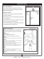
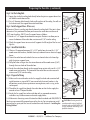
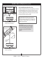
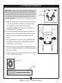
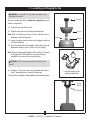
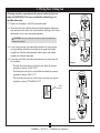
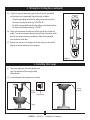
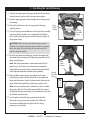
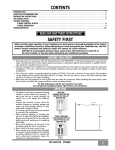
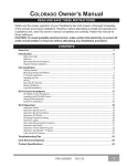
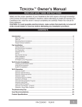
Tribeca Owner’s Guide and Installation Manual English Form# M6000-01 20120416 ©2012 Casablanca Fan Co. Welcome Your new Casablanca® ceiling fan is an addition to your home or office that will provide comfort and performance for many years. This installation and operation manual gives you complete instructions for installing and operating your fan. We are proud of our work. We appreciate the opportunity to supply you with the best ceiling fan available anywhere in the world. Before installing your fan, for your records and warranty assistance, record information from the carton and Casablanca nameplate label (located on the top of the fan motor housing). Cautions and Warnings Table Of Contents Preparing the Fan Site . . . . . . . . . . . . . . . . . . 3 1 • Getting Ready . . . . . . . . . . . . . . . . . . . . . . 6 2 • Installing the Ceiling Bracket . . . . . . . . 7 3 • Assembling and Hanging the Fan . . . . 8 4 • Wiring Your Ceiling Fan . . . . . . . . . . . . . 9 5 • Installing the Canopy . . . . . . . . . . . . . . . 10 6 • Assembling the Blades . . . . . . . . . . . . . . 11 7 • Installing the Switch Housing . . . . . . . . 12 8 • Installing the Wall Control . . . . . . . . . . 13 9 • Pairing the Remote . . . . . . . . . . . . . . . . . 14 10 • Safe-Exit . . . . . . . . . . . . . . . . . . . . . . . . . . . 14 11 • Operating Your Ceiling Fan . . . . . . . . 14 12 • Troubleshooting . . . . . . . . . . . . . . . . . . . 14 • READ THIS ENTIRE MANUAL CAREFULLY BEFORE BEGINNING INSTALLATION. SAVE THESE INSTRUCTIONS. • Use only Casablanca replacement parts. • To reduce the risk of personal injury, attach the fan directly to the support structure of the building according to these instructions, and use only the hardware supplied. • To avoid possible electrical shock, before installing your fan, disconnect the power by turning off the circuit breakers to the outlet box and associated wall switch location. If you cannot lock the circuit breakers in the off position, securely fasten a prominent warning device, such as a tag, to the service panel. • All wiring must be in accordance with national and local electrical codes and ANSI/NFPA 70. If you are unfamiliar with wiring, use a qualified electrician. • To reduce the risk of personal injury, do not bend the blade attachment system when installing, balancing, or cleaning the fan. Never insert foreign objects between rotating fan blades. • To reduce the risk of fire, electrical shock, or motor damage, do not use a solid-state speed control with this fan. Use only Casablanca speed controls. • This product conforms to UL STD 507 and is certified to STD C22.2 No. 113. • Wash your hands after your fan installation is complete. © 2012 Casablanca Fan Company 2 M6000-01 • 04/16/12 • Casablanca Fan Company Preparing the Fan Site Step 1 - Choose the Fan Site Proper ceiling fan location and attachment to the building structure are essential for safety, reliable operation, maximum efficiency, and energy savings. Choose a fan site where: • No object can come in contact with the rotating fan blades during normal operation. • e fan blades are at least 7 feet above the floor and the ceiling is at least 9 feet high. • e fan blades have no obstructions to airflow, such as walls or posts, within 30 inches of the fan blade tips. • e fan is directly below a joist or support brace that will hold the outlet box and the full weight of the fan. 9’ Minimum Ceiling Height 30” From Wall or Nearest Obstruction 7’ Minimum Blades to Floor Checklist for Existing Fan Site Suitable Existing Fan Site If you want to use an existing fan site, complete the following checklist to determine if the site is acceptable and safe for your new Casablanca fan. If you cannot check off every item, prepare a new fan site as described on this page. Fan Support System • Fan attaches directly to building structure. • Fan support system will hold full weight of the fan and light kit. Ceiling Hole • e outlet box clearance hole is directly below the joist or support brace. Outlet Box • e outlet box is an UL-approved octagonal 4” x 1-1/2” outlet box (or as specified by the support brace manufacturer). • e outlet box is secured to the joist or support brace by wood screws and washers through the inner holes of outlet box. • e outer holes of the outlet box are aligned with joist or support brace. • e bottom of the outlet box is recessed a minimum of 1/16” into ceiling. Wiring • e electrical cable is secured to outlet box by an approved connector. • Six inches of lead wires extend from outlet box. If your existing fan site is suitable, skip ahead to Section 2 • Installing the Ceiling Plate. Fan Support System Fan Support System Outlet Box Wiring 3 M6000-01 • 04/16/12 • Casablanca Fan Company Preparing the Fan Site (continued) Step 2 - Cut the Ceiling Hole 2-1. Locate the site for the ceiling hole directly below the joist or support brace that will hold the outlet box and fan. 2-2. Cut a 4” diameter hole through the drywall or plaster of the ceiling. You will use the hole to install the support brace and outlet box. Step 3 - Install a Support Brace, If Necessary Determine if there is a ceiling joist directly above the ceiling hole. If the joist is there, determine if it is positioned to allow you to recess the outlet box a minimum of 1/16” into the ceiling. If NOT, install a support brace as follows: 3-1. Attach a 2” x 4” support brace between two joists. Position it to allow you to recess the bottom of the outlet box a minimum of 1/16” into the ceiling. 3-2. Check the support brace to ensure it will support the full weight of the fan and light kit. Steps 2 – 3 Step 4 - Install the Outlet Box 4-1. Obtain a UL-approved octagonal 4” x 1-1/2” outlet box, plus two #8 x 1-1/2” wood screws and washers, available from any hardware store or electrical supply house. 4-2. Orient the outlet box so that both the inner and outer holes in the box align with the joist or support brace. 4-3. Drill pilot holes no larger than the minor diameter of the wood screws (5/64”) through the inner holes of the outlet box. 4-4. Attach the outlet box directly to the support brace or joist with two #8 x 1-1/2” Step 4 wood screws and washers. e bottom of the outlet box must be recessed a minimum of 1/16” into the ceiling. Step 5 - Prepare the Wiring 5-1. Make sure the circuit breakers to the fan supply line leads and associated wall switch location are turned off . If you cannot lock the circuit breakers in the off position, securely fasten a prominent warning device, such as a tag, to the service panel. 5-2. read the fan supply line through the outlet box so that the fan supply line extends at least 6” beyond the box. 5-3. Attach the fan supply line to the outlet box with an approved connector, available at any hardware store or electrical supply house. Step 5 5-4. Make certain the wiring meets all national and local standards and ANSI/NFPA 70. CAUTION: All wiring must be in You have now successfully prepared your ceiling fan site. For instructions to install accordance with national and local your ceiling fan, go to your fan manual and continue with Section 2 • Installing the electrical codes and ANSI/NFPA 70. If Ceiling Bracket. you are unfamiliar with wiring, use a qualified electrician. 4 M6000-01 • 04/16/12 • Casablanca Fan Company Installer’s Choice and Optional Accessories Understanding Mounting and Installer’s Choice Support Brace Standard Mounting Style Ceiling Outlet Box Casablanca’s 2-position mounting system provides you maximum installation flexibility and ease. You can install your fan in one of two ways, depending on ceiling height and your preference: standard or angled mounting. The steps in this manual include instructions for both mounting methods. For ceilings higher than 9 feet, you can purchase Casablanca extension downrods. All Casablanca fans use sturdy 3/4” diameter pipe to assure stability and wobble-free performance. Standard Mounting hangs from the ceiling by a downrod (included). CAUTION: To reduce the risk of personal injury, attach the fan directly to the support structure of the building according to these instructions, and use only the hardware supplied. Support Brace Ceiling Outlet Box 8 Angled Mounting Style 12 Angled Mounting recommended for a vaulted or angled ceiling. 5 M6000-01 • 04/16/12 • Casablanca Fan Company 1 • Getting Ready To install a ceiling fan, be sure you can do the following: • Locate the ceiling joist or other suitable support in ceiling. • Drill holes for and install wood screws. • Identify and connect electrical wires. • Lift 40 pounds. If you need help installing the fan, your Casablanca fan dealer can direct you to a licensed installer or electrician. Gathering the Tools You will need the following tools for installing the fan: • Electric drill with 9/64” bit • Standard screwdriver (magnetic tip recommended) • Phillips-head screwdriver (magnetic tip recommended) • Wrench or pliers • Ladder (height dependent upon installation site) Checking Your Fan Parts Carefully unpack your fan to avoid damage to the fan parts. Refer to the included Parts Guide. Check for any shipping damage to the motor or fan blades. If any parts are missing or damaged, contact your Casablanca dealer or call Casablanca Technical Support Department at 888-227-2178 (In Canada, call 1-866-268-1936). Installing Multiple Fans? If you are installing more than one fan, keep the fan blades and blade irons (if applicable) in sets, as they were shipped. Preparing the Fan Site Before you begin installing the fan, follow all the instructions in “Preparing the Fan Site.” Proper ceiling fan location and attachment to the building structure are essential for safety, reliable operation, maximum efficiency, and energy savings. WARNING! To avoid possible electrical shock, make certain that electricity is turned off at the circuit breaker or fuse box before attempting any installation or repair procedure. 6 M6000-01 • 04/16/12 • Casablanca Fan Company 2 • Installing the Ceiling Bracket CAUTION: To avoid possible electrical shock, before installing your fan, disconnect the power by turning off the circuit breakers to the outlet box and associated wall switch location. If you cannot lock the circuit breakers in the off position, securely fasten a prominent warning device, such as a tag, to the service panel. Isolator Ceiling Bracket 2-1. Note: The ceiling bracket may be mounted to an existing ceiling-fan-rated outlet box. If the outlet box is not ceiling-fan-rated, Drill two pilot holes into the wood support structure. The pilot holes should be 9/64” in diameter and through the outermost holes in the outlet box. 2-2. Your fan comes with four neoprene noise isolators. Position the isolators between the ceiling bracket and the ceiling by inserting the raised areas on each isolator into the holes in the ceiling bracket. Step 2-2 2-3. Align the slotted holes in the ceiling bracket with the pilot holes you drilled in the wood support structure. Note: The isolators should be flush against the ceiling. 2-4. Place a flat washer on each of the two 3” wood screws and pass the screws through the slotted holes in the ceiling bracket into the pilot holes you drilled. 2-5. Tighten the screws into the 9/64” pilot holes; do not use lubricants on the screws. Do not over tighten. Flat Washer 3” Wood Screw 7 M6000-01 • 04/16/12 • Casablanca Fan Company Steps 2-3 – 2-5 3 • Assembling and Hanging the Fan WARNING: Fan may fall if not assembled as directed in these installation instructions. Downrod You can assemble your fan for standard or angled mounting as shown in steps below. 3-1. Unbundle the wires from the fan. 3-2. Feed the wires from the fan through the downrod. Note: Make sure all the wires are on the same side of the metal dowel pin inside the downrod. 3-3. Loosen the square head setscrew on the adapter in order to install the downrod. 3-4. Insert the downrod into the adapter. Tighten by turning the downrod assembly at least 4-5 full turns until it stops. Canopy Setscrew Adapter Steps 3-1 – 3-4 Note: When the downrod assembly is fully installed, 2-3 threads on the pipe will still be visible; this is normal. Securely retighten the setscrew with a wrench or pliers. WARNING: If the setscrew is not tightened securely, the fan may fall. 3-5. (Optional) - The wires can be cut (shortened), but leave at least 8” extending from the top of the downrod. 3-6. Raise the fan and place the downrod ball into the ceiling bracket. For angled ceilings, point opening toward peak Ceiling Bracket Downrod Step 3-6 8 M6000-01 • 04/16/12 • Casablanca Fan Company 4 • Wiring Your Ceiling Fan All wiring must be in accordance with national and local electrical codes and ANSI/NFPA 70. If you are unfamiliar with wiring, use a qualified electrician. CEILING OM FR 4-1. Make sure the power is still off at the breaker box. green or bare (grounding) OM FAN FR green with yellow stripe F Step 4-3 T blue black 9 M6000-01 • 04/16/12 • Casablanca Fan Company FRO blue (light out) white Step 4-4 CEIL ING BR ECEIVER white (common out) Wire Connector MR RO M black (fan out) O FR 4-3. Using a large (orange) wire connector, connect the green or bare wire (grounding) wire from the ceiling to the green with yellow striped wire from the ceiling bracket and the green with yellow striped wire from the downrod. 4-4. Using the small (blue) wire connector, connect the wires from the fan as follows: • The blue wire from the fan to the blue wire from the receiver (marked on red tag “LIGHT OUT”) • The black wire from the fan to the black wire from the receiver (marked on red tag “FAN OUT”) • The white wire from the fan to the white wire from the receiver (marked on red tag “COMMON OUT”) green with yellow stripe CAUTION: Be sure no bare wire or wire strands are visible after making connections. KE 4-2. To connect the wires, hold the bare metal leads together and place a wire connector over them, then twist clockwise until tight. For all wire connections use the wire connector provided. M FA N AC 4 • Wiring Your Ceiling Fan (continued) 4-5. Using the large wire connectors, connect the white wire (grounded) and the black wire (ungrounded) from the ceiling as follows: • The white (grounded) wire from the ceiling to the white wire from the receiver (marked on white tag “NEUTRAL IN”) • The black (ungrounded) wire from the ceiling to the black wire from the receiver (marked on white tag “LIVE IN”) OM CEILING FR FR OM black white Step 4-5 black (ungrounded) white (grounded) 4-6. Check each connection to make sure no bare wire or wire strands are visible. Turn wire connectors upward and push them up into the outlet box. Be sure to separate the grounded wires from the ungrounded wires inside the outlet box. 4-7. Position the receiver in the canopy so that the antenna is close to the edge of the ceiling bracket for clear reception. R RECEIVE 5 • Installing the Canopy 5-1. Raise the canopy over the ceiling bracket and align the two holes of the canopy and the ceiling bracket. 5-2. Insert and tighten the canopy screws securely. Hanger Bracket Canopy Screw Canopy Screw Canopy Step 5-1 Steps 5-2 10 M6000-01 • 04/16/12 • Casablanca Fan Company 6 • Assembling the Blades 6-1. Using the provided Allen wrench, attach each blade to the blade iron using three barrel nuts and three decorative screws as shown. Blade Iron Barrel Nut Note: You may place the decorative screws and barrel nuts facing up or down. 6-2. Remove the two orange shipping rings from motor by lifting up on the edge of the rings. 6-3. Align the five holes in the blade iron ring and the decorative ring with the five holes in the bottom of the motor and partially install the five blade mounting screws. 6-4. Once all five of the screws are partially installed, tighten them securely. Decorative Screw Step 6-1 Allen Wrench Blade Iron Ring Decorative Ring Blade Mounting Screw Shipping Ring Step 6-2 Steps 6-3 - 6-4 11 M6000-01 • 04/16/12 • Casablanca Fan Company 7 • Installing the Switch Housing 7-1. To attach the upper switch housing, partially install two housing assembly screws into the switch housing mounting plate. 7-2. Feed the upper plug connector through the center opening of the housing. 7-3. Align the keyhole slots in the housing with the housing assembly screws. 7-4. Turn the housing counterclockwise until the housing assembly screws are firmly situated in the narrow end of the keyhole slots. Install the remaining screw into the housing. Tighten all three screws firmly. Upper Switch Housing Housing Assembly Screw Steps 7-1 – 7-4 CAUTION: Make sure the upper switch housing is securely attached to the switch housing mounting plate. Failure to properly attach and tighten all three assembly screws could result in the switch housing fixture falling. 7-5. To attach the lower switch housing, connect the upper plug connector from the motor to the lower plug connector in the lower switch housing. Note: Both plug connectors are polarized and will only fit together one way. Make sure the connectors are properly aligned before connecting them. Incorrect connection could cause improper operation and damage the product. Housing Assembly 7-6. Place the lower switch housing assembly over the upper Screw switch housing. Align the side screw holes in the upper and lower switch housings. Attach the lower switch housing to the upper switch housing with three housing assembly screws. Note: You can customize your Casablanca fan with a number of accessory light kits. To install an optional light kit, remove the logo cap by removing the two screws located on the inside of the lower switch housing. 7-7. Use the optional switch housing cap to attach light kits that mount using a center stem attachment. Follow the instructions included with the light kit for the wiring, mounting, and assembly. Lower Switch Housing Steps 7-5 – 7-6 Step 7-7 12 M6000-01 • 04/16/12 • Casablanca Fan Company 8 • Installing the Wall Control WARNING! To avoid possible electrical shock, make certain that electricity is turned off at the circuit breaker or fuse box before attempting any installation or repair procedure. 9-1. Use only the Casablanca wall control. Note: Wall Control should only be used on Casablanca 5xxxx Series Fans. Steps 9-3 9-2. Do not use any additional control with your fan (for example, dimmer, or fan speed control). 9-3. Remove the screws and cover plate from the existing switch box. 9-4. Remove the screws holding the switch in the switch box. 9-5. Pull the existing switch from the switch box to expose the wire connections. Steps 9-7 9-6. Remove the wires from the switch. 9-7. Connect black wire (ungrounded) to black wire (ungrounded), white wire (grounded) to white wire (grounded), and green or bare copper wire (grounding) to green or bare copper (grounding). Make sure each wire connection is secured with a wire connector. 9-8. Push all connections to the back of the switch box. Be sure to separate the grounded wires from the ungrounded wires inside the switch box. Steps 9-8 9-9. Insert wall control into outlet box, and secure using the two switch mounting screws. 9-10. Install the cover plate using a Phillips Head screwdriver to secure the two cover plate screws. Note: The wall control is mounted in the switch box, but is not wired into the box. It is battery operated. Steps 9-9 13 M6000-01 • 04/16/12 • Casablanca Fan Company Steps 9-10 9 • Pairing the Remote Pairing the Remote Note: The remote is must be paired before the fan will operate. Learning Mode - This feature shall be initiated by cycling the power to the fan. For 3 minutes after cycling power to the fan, the pairing operation can be performed using the wall control. Begin by pressing both the fan power button and the High for at least 3 seconds. This will send an encoded binary bit message to a target receiver-controller. The fan will turn at the lowest speed signifying that the remote pairing process is complete. 10 • Safe-Exit Safe-Exit® ( for use with optional accessory light kit) The Safe-Exit Program gives you about thirty seconds of light when you turn the lights off, enabling you to exit your home before the lights go out. To enter the Safe-Exit Program: Incandescent Lighting 1. Press the fan power button off for at least three seconds to initiate the Safe-Exit Mode. 2. The lights will flash for visual confirmation. 3. The lights will stay on 50% brightness for 20 seconds and then begin to dim. After a total of 30 seconds, the lights will be completely off. CFL Lighting 1. Press the fan power button off for at least three seconds to initiate the Safe-Exit Mode. 2. The lights will flash for visual confirmation. 3. The lights will stay on 100% brightness for 30 seconds. After a total of 30 seconds, the lights will turn off. 14 M6000-01 • 04/16/12 • Casablanca Fan Company 11 • Operating Your Ceiling Fan Battery Note: The remote will not operate until the battery’s protective film is removed. 1. Remove battery holder by pressing the battery icon on the front of the holder. 2. Remove protective film from battery surface. 3. Reinstall battery holder. Battery Fan Power The fan power button controls power to the fan only. Figure 1. Speed Control There are four individual speed settings for the fan. Each speed is indicated by the number on the controller and an audible tone for each speed. Battery Holder To select the desired fan speed: Press the number on the controller corresponding to the speed desired. 4 is high, 3 medium, 2 low, and 1 ultra-low. Figure 2. Figure 1 Note: It is normal for the fan to start in the “High” position from “Off” before changing to the selected speed. Reversing Airflow The direction of airflow can be changed from downward to upward or from upward to downward. Figure 3. Figure 2 To reverse the airflow: 1. Make sure the fan is on and blades are turning. 2. Press the reverse button. You will hear a series of clicks from the fan as it speeds up before coming to a stop and changing direction. Lights ( for use with optional accessory light kit) To turn the lights off and on, press either the up or down arrow. To adjust the light level, press and hold either the down arrow to dim the light or the up arrow to return the light to full brightness. WARNING! Your fan automatically detects what type of bulbs that are installed each time it is powered up. NOTE: If CFL bulbs are detected, the dimming function will automatically be disabled. Remember to turn off the lights before replacing bulbs. 15 M6000-01 • 04/16/12 • Casablanca Fan Company Figure 3 Figure 4 12 • Troubleshooting Problem: Nothing happens; fan does not move. 1.Turn power on, replace fuse, or reset breaker. 2.Loosen canopy, check all connections according to the wiring the fan section. 3.Remove the shipping bumpers. 4. Make sure the wall control is paired. (See Pairing the Wall Control on page 14.) Problem: Noisy operation. 1.Tighten the blade assembly screws and blade iron armature screws until snug. 2.Check to see if the blade is cracked. If so, replace all the blades. Problem: Excessive wobbling. 1.If your fan wobbles when operating, use the enclosed balancing kit and instructions to balance the fan. 2.Tighten all blade iron screws. 3.Turn power off, support fan very carefully, and check that the hanger ball is properly seated. If you need parts or service assistance, please call 888-227-2178 (In Canada, call 1-866-268-1936) or visit us at our website at http://www.CasablancaFanCo.com. Casablanca Fan Company 7130 Goodlett Farms Pkwy. #400 Memphis, Tennessee 38016 AUTHORIZED SERVICE CENTERS For the most updated listing of Casablanca Authorized Service Centers, visit www.CasablancaFanCo.com/servicecenters or call toll free 1-888-227-2178. 16 M6000-01 • 04/16/12 • Casablanca Fan Company