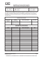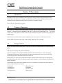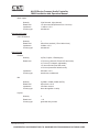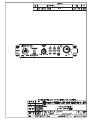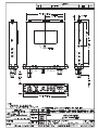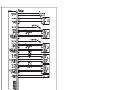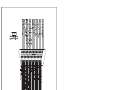
1
SPECIAL NOTICE
This product is now licensed to Anodyne Electronics Manufacturing (AEM) from Northern
Airborne Technology (NAT). AEM is responsible for all matters related to this product, including
sales, support and repair services.
Please note the transition to convert product manuals and supporting documentation is an
ongoing process and is being addressed on an ‘as needed’ basis.
All references to NAT product part numbers (and associated images) are equivalent to AEM
product part numbers.
Contact info:
Anodyne Electronics Manufacturing Corp.
#15-1925 Kirschner Road
Kelowna B.C. Canada
V1Y 4N7
Email: [email protected]
Toll Free: 1-888-763-1088
Phone: 1-250-763-1088
Fax: 1-250-763-1089
www.aem-corp.com
SM69
AA12S Series
Compact Audio Controller
INSTALLATION AND OPERATION MANUAL
Rev: 2.00 April 14, 2012
Anodyne Electronics Manufacturing Corp.
15-1925 Kirschner Road
Kelowna, BC, Canada.
V1Y 4N7
Telephone (250) 763-1088
Facsimile (250) 763-1089
Website: www.aem-corp.com
© 2012 Anodyne Electronics Manufacturing Corp. (AEM),
All Rights Reserved
CONFIDENTIAL AND PROPRIETARY TO ANODYNE ELECTRONICS MANUFACTURING CORP.
AA12S Series Compact Audio Controller
SM69 Installation and Operation Manual
COPYRIGHT STATEMENT
© 2012 Anodyne Electronics Manufacturing Corp. (AEM), All Rights Reserved
This publication is the property of AEM and is protected by Canadian copyright
laws.
No part of this document may be reproduced or transmitted in any form or by any
means including electronic, mechanical, photocopying, recording, or otherwise,
without the prior written permission of AEM.
Installation and Operation Manual
Page ii
ENG-FORM: 820-0100.DOTX
CONFIDENTIAL AND PROPRIETARY TO ANODYNE ELECTRONICS MANUFACTURING CORP.
AA12S Series Compact Audio Controller
SM69 Installation and Operation Manual
Prepared By:
Checked By:
Tony Pearson
Designer
Apr 14, 2012
Approved By:
Tom Betzelt
Product Support
Manager
May 28, 2012
Loen Clement
Designer
May 24/12
The status of this installation and operation manual is controlled by issue shown on the
title page. The status of each section is controlled by revision shown in the footer of
each page. All revisions affecting sections of this manual have been incorporated into
the latest issue.
ISSUE/REVISION RECORD
Manual Issue
Number
Section
Revision Number
Revision Description
Issue Date
4.01
Section 1 Rev: 1.00
Section 2 Rev: 1.00
Section 3 Rev: 1.00
Update to current templates.
Nov 7, 2008
AEM MANUAL REVISIONS
Section
Revisions Number
Revision Description
Date
All
2.00
Updated template
April 14, 2012
Installation and Operation Manual
Page iii
ENG-FORM: 820-0100.DOTX
CONFIDENTIAL AND PROPRIETARY TO ANODYNE ELECTRONICS MANUFACTURING CORP.
AA12S Series Compact Audio Controller
SM69 Installation and Operation Manual
Table of Contents
Section
Title
1.0
Description
1.1
1.2
1.3
1.4
1.4.1
1.4.2
1.4.3
1.5
Introduction
Purpose of Equipment
Design Features
Specifications
Electrical Specifications
Physical Specifications
Environmental Specifications
Unit Nomenclature
2.0
Installation
2.1
2.2
2.2.1
2.3
2.4
2.4.1
2.4.2
2.4.3
2.4.4
2.5
2.5.1
2.5.2
2.6
2.7
Introduction
Unpacking and Inspection
Warranty
Continued Airworthiness
Installation Procedures
Warnings
Cautions
Cabling and Wiring
Post-Installation Checks
Adjustments and Connections
Left Side Adjustments
Right Side Adjustments
Accessories Required But Not Supplied
Installation Drawings
3.0
Operation
3.1
3.2
3.3
3.3.1
3.3.2
3.3.3
3.3.4
3.3.5
Introduction
General Information
Controls and Indicators
Radio Selection
Intercom
PILOT ISO / NORM Modes
Entertainment Audio
Automatic Fail-safe
Installation and Operation Manual
Page
1-1
1-1
1-1
1-2
1-2
1-5
1-5
1-5
2-1
2-1
2-1
2-1
2-1
2-1
2-2
2-2
2-3
2-3
2-3
2-4
2-4
2-4
3-1
3-1
3-1
3-1
3-2
3-3
3-4
3-4
Page iv
ENG-FORM: 820-0100.DOTX
CONFIDENTIAL AND PROPRIETARY TO ANODYNE ELECTRONICS MANUFACTURING CORP.
AA12S Series Compact Audio Controller
SM69 Installation and Operation Manual
Section 1.0 Description
1.1
Introduction
Information in this section consists of product description, design features and specifications for the
AA12S Series Compact Audio Controller. All derivative product information shall be contained in the
applicable manual supplement, which may be obtained from AEM as required.
Review all notes, warnings and cautions.
1.2
Purpose of Equipment
The AA12S is a compact Dzus-mounted audio controller with an integral 4-place stereo voice-activated
intercom. It provides intercom capabilities for the pilot, co-pilot and two passengers (PAX). The AA12S
accepts stereo music inputs from either portable or fixed entertainment systems to produce high quality stereo
headset output.
Radio functions include selectable transmit capability for pilot and co-pilot on 3 COM radios and a PA.
Receive audio selections include COM1, COM2, COM3, MKR, NAV, ADF, and DME.
1.3
Design Features
All four mics have individual VOX gating. Each gate may also be activated with the corresponding ICS
keyline.
ICS muting is automatic during radio transmission.
The unit is supplied to suit a standard AEM bi-directional ICS audio TIE line for multi-unit interface
(configuration dependent). The crew and PAX are always connected except in the case of Pilot ISO
mode, when the pilot is disconnected from the ICS tie line.
If required, one or more receiver audio inputs may be configured at the factory prior to ordering as an
unswitched Direct Audio input. A new part number may be assigned. Contact AEM Product Support for
further information.
The following audio levels can be adjusted at the time of installation, or during service by an approved
dealer, using individual level trimpots.
-ICS Balance
-ICS Bass level
-Music Balance
-Music Bass level
April 14, 2012 Rev: 2.00
-Music Mute level
-RX Balance
-RX volume level
-Sidetone level
Page 1-1
ENG-FORM: 800-0100.DOTX
CONFIDENTIAL AND PROPRIETARY TO ANODYNE ELECTRONICS MANUFACTURING CORP.
AA12S Series Compact Audio Controller
SM69 Installation and Operation Manual
1.4
Specifications
1.4.1
Electrical Specifications
Power Supply
Linear regulator with reverse and over voltage protection.
Input voltage:
11-30 Vdc operating.
30.3 Vdc (maximum)
13.8 Vdc or 27.5 Vdc @ 600 mA (nominal, one input for both)
11.0 Vdc (minimum)
Lighting Voltage
AA12S-001
AA12S-004
27.5 Vdc @ 200 mA max.
13.5 Vdc @ 400 mA max.
Note: The AA12S is not designed to operate under emergency electrical system conditions for 14 Vdc
operation.
Input Signals
Microphone
Quantity
Rated level
Impedance
Circuitry type
4 (Pilot, Copilot, 2 Passengers).
250 mVrms nominal (125 to 500 mVrms)
150 Ohm r10 %
Unbalanced
TX Keyline
Quantity
Rated level
2 (Pilot, Copilot).
Ground activates keyline, 20 mA source current
ICS Keyline
Quantity
Rated level
4 (Pilot, Copilot, 2 Passengers).
Ground activates keyline, 1 mA source current
Receive Audio
Quantity
Rated level
Impedance
Circuitry type
April 14, 2012 Rev: 2.00
7 (3 COM, 4 NAV).
2.5 Vrms nominal (1.3 to 5.0 Vrms)
1 kOhm r10 % (1 to 3 kOhm for sidetone)
Unbalanced
Page 1-2
ENG-FORM: 800-0100.DOTX
CONFIDENTIAL AND PROPRIETARY TO ANODYNE ELECTRONICS MANUFACTURING CORP.
AA12S Series Compact Audio Controller
SM69 Installation and Operation Manual
Music Inputs
Quantity
Rated level
Impedance
Circuitry type
2 (left channel, right channel)
1.4 Vrms nominal (850 mVrms to 2.4 Vrms)
11 kOhm r10 %
unbalanced
Bi-directional Signals
ICS TIE Channel
Quantity:
Rated level:
Impedance:
Circuitry type:
1
340 mVrms nominal (170 to 680 mVrms)
2 kOhm r10 %
unbalanced
Quantity
4 (Pilot, Copilot, 2 Passengers)
Rated level
>5.5 Vrms (>100 mW, RX and ICS and music)
>0.7 Vrms (TX sidetone, adjustable)
1.5 Vrms nominal (Pilot ISO mode)
>0.2 Vrms (Automatic failsafe mode)
Impedance
Circuitry type
300 Ohm r10 %
transformer, unbalanced
Quantity
Rated level
Impedance
Circuitry type
4 (COM1, COM2, COM3 and PA)
250 mVrms r10 %
150 Ohm nominal
direct throughline via relay
Quantity
Rated level
Circuitry type
3
1 A
grounded relay contact
Output Signals
Phones
Mic
Keyline
April 14, 2012 Rev: 2.00
Page 1-3
ENG-FORM: 800-0100.DOTX
CONFIDENTIAL AND PROPRIETARY TO ANODYNE ELECTRONICS MANUFACTURING CORP.
AA12S Series Compact Audio Controller
SM69 Installation and Operation Manual
Audio Performance
As per RTCA DO-170 Product Classification: 1a except where noted
*Manufacturers Specification
Rated Output Power
**Exceeds DO-170 requirement
100 mW min. into 300 :
Audio frequency Response
Distortion
d3dB down from 350 - 6000 Hz
d3dB down from 350 - 3000 Hz
d3dB down from 350 - 3000 Hz
d3dB down from 300 - 15000 Hz (Music Bass
control at mid setting)
d 10%, d3 % typical (350 to 6000 Hz)
Input crosstalk
Output crosstalk
Mic crosstalk
-37 dB max.*
-55 dB max.
<200 uVrms*
Receive
Intercom
ICS Tie
Music
Input
Audio noise:
-60 dB max**
Output Regulation
d3 dB variance (350 to 6000 Hz)
Audio Communication
Loud & Clear
ICS Volume controls
t35 dB*, 40 dB nominal
Music Volume controls
t35 dB*, 40 dB nominal
Receive Input impedance
1 k: r10 %
Mic Input impedance
150 : r10 %
Music Input impedance
11 k: r10 %
ICS Tie Line
2 k: r10 %
April 14, 2012 Rev: 2.00
Page 1-4
ENG-FORM: 800-0100.DOTX
CONFIDENTIAL AND PROPRIETARY TO ANODYNE ELECTRONICS MANUFACTURING CORP.
AA12S Series Compact Audio Controller
SM69 Installation and Operation Manual
1.4.2
1.4.3
Physical Specifications
Height
1.15” (29.2 mm) max.
Depth
5.80” (147.3 mm) max., behind panel
Width
4.95” (125.7 mm) max, behind panel
Weight
1.2 lbs (0.50 kg)
Mounting
Dzus rail, four fasteners, 5.366” horizontal spacing,
vertical spacing
Faceplate
Lighted panel is laser-engraved acrylic edge lit with blue-white
backlighting.
Material/Finish
Brushed aluminum with conversion coating
Connectors
One 25-pin female D-min connector with jackposts
One 44-pin male high-density D-min connector with jackposts
and 0.750”
Environmental Specifications
Temperature:
-20q C. to +55q C
Altitude
50,000 feet
Shock
6g/11ms, 20g/11ms
Qualification of the AA12S Series Compact Audio Controller was completed in accordance with DO-160D
Env. Cat. [(A1)(D1)X]BXB[(SMB)(UF)]XXXXXXZBAXXXMXXXX
1.5
Unit Nomenclature
Variants of the AA12S series Compact Audio Controllers are identified as follows:
AA12S-002
Same as AA12S-001 with Faceplate changes
(ADF becomes ADF/MKR, DME/MKR becomes TRFC)
AA12S-004
Same as AA12S-001 with 14 Vdc lighting
AA12S-005
Same as AA12S-004 with custom faceplate
(ADF becomes ADF/MKR, DME/MKR becomes TRFC).
End of Section 1.0
April 14, 2012 Rev: 2.00
Page 1-5
ENG-FORM: 800-0100.DOTX
CONFIDENTIAL AND PROPRIETARY TO ANODYNE ELECTRONICS MANUFACTURING CORP.
AA12S Series Compact Audio Controller
SM69 Installation and Operation Manual
Section 2.0 Installation
2.1
Introduction
Information in this section consists of unpacking and inspection procedures, installation procedures, postinstallation checks and installation drawings for the AA12S Series Compact Audio Controller.
Review all notes, warnings and cautions.
2.2
Unpacking and Inspection
Unpack the equipment carefully. Inspect the unit visually for damage due to shipping and report all such
claims immediately to the carrier involved. Check that all items listed below are present before proceeding
and report any shortage immediately to your supplier:
- AA12S Series Compact Audio Controller
- Product Information Card
- Certificate of Conformity or Release Certification
2.2.1
Warranty
All Anodyne Electronics Manufacturing Corp. (AEM) products are warranted for 2 years. See the website
www.aem-corp.com/warranty for complete details.
2.3
Continued Airworthiness
Maintenance of the AA12S Series Compact Audio Controller is ‘on condition’ only. Periodic maintenance
of this product is not required.
2.4
Installation Procedures
2.4.1
Warnings
WARNING:
High volume settings can cause hearing damage.
Set the headset volume control to the minimum volume setting prior to
conducting tests, and slowly increase the headset volume to a
comfortable listening level.
April 14, 2012 Rev: 2.00
Page 2-1
ENG-FORM: 805-0100.DOTX
CONFIDENTIAL AND PROPRIETARY TO ANODYNE ELECTRONICS MANUFACTURING CORP.
AA12S Series Compact Audio Controller
SM69 Installation and Operation Manual
2.4.2
Cautions
CAUTION:
The shielding and routing of the MIC and ICS TIE LINES used in the AA12S
installation is very critical and poor performance of the aircraft audio system will
result if these issues are not handled properly.
The operation of the VOX intercom can be severely degraded by the quality and
type or mix of microphones used in the aircraft. If one user has a 'hot'
microphone, it will increase the electrical signal to the VOX circuit and the VOX
SQUELCH will have to be set to quiet this microphone. The other microphones
may not be able to generate enough electrical energy to overcome this VOX
SQUELCH setting, and will break up or not be heard at all.
2.4.3
Cabling and Wiring
All wire shall be selected in accordance with the original aircraft manufacturer's Maintenance Instructions
or AC43.13-1B Change 1, Paragraphs 11-76 through 11-78. Unshielded wire types shall qualify to
MIL-W-22759 as specified in AC43.13-1B Change 1, Paragraphs 11-85, 11-86, and listed in Table 11-11.
For shielded wire applications, use Tefzel MIL-C-27500 shielded wire with solder sleeves (for shield
terminations) to make the most compact and easily terminated interconnect. Follow the connector map in
Section 2.7 as required.
Coaxial cable shall be selected in accordance with MIL-C-17 unless otherwise specified. Do not use coax
cable with PVC insulation. Teflon dielectric cable is encouraged at or above VHF frequencies or where
cable runs exceed 8 feet. Note that at VHF frequencies, cables losses due to long cable runs and tight
bends may reduce the ERP (Effective Radiated Power) by greater than 50%.
Allow 3" from the end of the shielded wiring to the shield termination to allow the connector hood to be
easily installed. Reference the interconnect drawing in Section 2.7 for shield termination details. Note that
the hood is a "clamshell" hood, and is installed after the wiring is complete. Aircraft harnessing shall
permit the unit to be removed from the panel for easy access to all side adjustments. Do NOT mount the
unit until all adjustments have been performed.
Maintain wire segregation and route wiring in accordance with the original aircraft manufacturers
Maintenance Instructions. Coaxial cables shall be routed separately from existing wire bundles in the
aircraft to minimize electromagnetic coupling effects.
Unless otherwise noted, all wiring shall be a minimum of 24 AWG, except power and ground lines, which
shall be a minimum of 22 AWG. Reference the Interconnect drawing for additional specifications. Check
that the ground connection is clean and well secured, and that it shares no path with any electrically noisy
aircraft accessories such as blowers, turn and bank instruments or similar loads. Power to this unit must
be supplied from a separate circuit breaker or fuse (fast blow), and not attached to any other circuit
breaker without additional protection. Verify that the selected circuit breaker size and wire gauge are
adequate for the installation using the techniques specified in AC43.13-1B Change 1, Paragraphs 11-47
through 11-51 and 11-66 through 11-69.
April 14, 2012 Rev: 2.00
Page 2-2
ENG-FORM: 805-0100.DOTX
CONFIDENTIAL AND PROPRIETARY TO ANODYNE ELECTRONICS MANUFACTURING CORP.
AA12S Series Compact Audio Controller
SM69 Installation and Operation Manual
2.4.4
Post-Installation Checks
2.4.4.1
Voltage/Resistance Checks
Do not attach the AA12S until the following conditions are met.
Check the following:
a) Check P101, pin <1> for avionics buss voltage.
b) Check P101, pin <16> for continuity to ground (less than 0.5 ).
c) Check P101, pins <9>, <10>, <11> and <12> for continuity to ground when the relevant
switch is closed.
d) Check P301, pin <5> for avionics lighting buss voltage relative to ground (with lighting on).
e) Check P301 pin <17> for continuity to ground.
2.4.4.2
Power On Checks
Power up the aircraft’s systems and confirm normal operation of all functions of the AA12S. Refer to
Section 3 (Operation) for specific operational details.
a) Install the AA12S and power up the aircraft’s systems. Turn on the radios and accessories
required for the system.
b) Check for correct radio audio and adjust for an acceptable level.
c) Perform all installed functions, and check the ICS and TX functions for all users. Refer to
Section 3 (Operation) for specific operational details.
Note:
Significantly different headsets may have different microphone characteristics.
Upon satisfactory completion of all performance checks, make all required log book entries, electrical
load, weight and balance amendments and other documentation as required by your local regulatory
agency before releasing the aircraft for service.
2.5
Adjustments and Connections
The unit is shipped from the factory with all internal adjustments set to the normal test levels. Once
installed in the aircraft, it may be desirable to change some of these settings to best suit the local
operating environment. The internal adjustments are located along the sides of the unit.
2.5.1
ICS
BAL
R
Left Side Adjustments
ICS
BASS
MUSIC
MUTE
L
April 14, 2012 Rev: 2.00
The adjustments found on the left side of the unit are:
- ICS BAL R/L, which controls the ICS Balance
- ICS BASS, which controls the ICS bass level
- MUSIC MUTE, which controls the Music mute level.
Page 2-3
ENG-FORM: 805-0100.DOTX
CONFIDENTIAL AND PROPRIETARY TO ANODYNE ELECTRONICS MANUFACTURING CORP.
AA12S Series Compact Audio Controller
SM69 Installation and Operation Manual
2.5.2
RX
BAL
R
Right Side Adjustments
RX
VOL
L
2.6
TX
S/T
MUSIC MUSIC
BASS
BAL
R
L
The adjustments found on the left side of the unit are:
- RX BAL R/L, which controls the RX Balance
- RX VOL, which controls the RX volume level
- MUSIC BASS, which controls the Music Bass level
- MUSIC BAL R/L, which controls the Music balance.
- TX S/T, which controls the sidetone level
Accessories Required But Not Supplied
Installation kit p/n AA12S-IKC (crimp) is required to complete the installation. The kit consists of one
44-Pin D-min Female Crimp Kit (AEM Part No. D44SL-IKC) and one 25-Pin D-min Male Crimp Kit
(AEM Part No. D25PL-IKC).
D44SL-IKC consists of
Quantity
1
44
1*
1*
1
Description
D-min 44 Socket Housing
Mini D Crimp Socket
Jack Screw Set
Lock Clip Set
25 Pin Connector Hood
AEM Part No.
20-20-044
20-26-703
20-27-002
20-27-004
20-29-026
Description
D-min 25 Socket Housing
MS Crimp Pin
Jack Screw Set
Lock Clip Set
25 Pin Connector Hood
AEM Part No.
20-11-025
20-26-891
20-27-002
20-27-004
20-29-026
D25PL-IKC consists of
Quantity
1
25
1*
1*
1
* Use as required.
2.7
Installation Drawings
DOCUMENT
AA12S-001
AA12S\001\403-0
AA12S\001\405-0
AA12S\001\905-0
AA12S\001\922-0
AA12S-004
AA12S\004\403-0
AA12S\004\405-0
REV.
DESCRIPTION
TYPE
SERIAL NO.
1.10
1.10
1.10
1.10
Compact Stereo Audio Controller
Compact Stereo Audio Controller
Compact Stereo Audio Controller
Compact Stereo Audio Controller
Interconnect
Connector Map
Faceplate
Mechanical Installation
All
All
All
All
1.00
1.00
Compact Stereo Audio Controller
Compact Stereo Audio Controller
Interconnect
Connector Map
All
All
Section 2.0 ends following the above documents
April 14, 2012 Rev: 2.00
Page 2-4
ENG-FORM: 805-0100.DOTX
CONFIDENTIAL AND PROPRIETARY TO ANODYNE ELECTRONICS MANUFACTURING CORP.
R
L
R
L
MUSIC MUSIC
BASS
BAL
MUSIC
MUTE
RX
VOL
ICS
BASS
RX
BAL
L
ICS
BAL
R
TX
S/T
AA12S Series Compact Audio Controller
SM69 Installation and Operation Manual
Section 3.0 Operation
3.1
Introduction
Information in this section consists of functional and operational procedures for the AA12S Series
Compact Audio Controller.
3.2
General Information
The AA12S is a compact Dzus-mounted audio controller with an integral 4-place stereo voice-activated
intercom. It provides intercom capabilities for the pilot, copilot and two passengers (PAX). The AA12S
accepts stereo music inputs from either portable or fixed entertainment systems to produce high quality
stereo headset output.
VOX/TX Annumnciator
RX Select Switches
TX Select Switch
Radio functions include selectable transmit capability for pilot and copilot on 3 COM radios and a PA.
Receive audio selections include COM1, COM2, COM3, MKR, NAV, ADF, and DME.
3.3
Controls and Indicators
3.3.1
Radio Selection
3.3.1.1
Receive
The AA12S is typically configured to select the RX audio from three transceivers and up to four additional
receivers.
The RX Select switches are white double-throw centre-off switches. Receiver audio can be selected by
setting the appropriate RX select switch to the down position.
Transceiver audio can either be selected by setting the appropriate RX select switch to the up position, or
as a function of the TX select switch. The transceiver that is selected by the TX select switch is also
automatically selected for receive. Receive/sidetone audio for the selected COM is automatically
provided.
When a switch is in the centre-off position, no transceiver/receiver audio is selected.
April 14, 2012 Rev: 2.00
Page 3-1
ENG-FORM: 806-0100.DOTX
CONFIDENTIAL AND PROPRIETARY TO ANODYNE ELECTRONICS MANUFACTURING CORP.
AA12S Series Compact Audio Controller
SM69 Installation and Operation Manual
3.3.1.2
Transmit
The TX select switch is a 4-position rotary control that provides radio selection for up to three transceivers
and a PA. By selecting the desired transceiver and pressing the external TX PTT switch, the AA12S is
activated for transmit operation, connecting the respective mic to the selected transceiver. The
transceiver that is selected by the TX select switch is also automatically selected for receive. The front
panel annunciator will illuminate green to indicate transmit operation (see section 3.3.1.3.)
TX selections are available only to the pilot and copilot. Activation of either TX PTT input connects the
user’s MIC to the selected COM, and activates the output PTT to the selected COM. When PTT is
pressed, all audio except the sidetone of the selected COM and NAV inputs is removed from the
headphone of the particular PTT user. The sidetone of the active COM is provided from the COM radio.
The PA position provides PA mic audio and PA keyline to an external amplifier (e.g. AA21, AA23, PA250)
for use as either a Loudhailer or Passenger Address system.
A priority transmission feature allows the pilot to override the co-pilot.
3.3.1.3
VOX/TX Annunciator
The VOX/TX Annunciator is a bicolour LED that indicates the intercom status.
During VOX activity, the annunciator LED is illuminated red. If TX is keyed with no ICS or sidetone, the
annunciator LED is illuminated green. If TX is keyed with mic or sidetone, the combination of red and
green will cause the LED to appear amber.
Note:
3.3.2
If the LED is still illuminated green after transmission is concluded, this indicates a possible stuck
mic.
Intercom
ICS VOL/VOX Squelch Control
VOX/TX Annunciator
The VOX and ICS VOL control is a fluted concentric knob, with the ICS volume on the centre knob, and
the VOX control on the outer knob.
April 14, 2012 Rev: 2.00
Page 3-2
ENG-FORM: 806-0100.DOTX
CONFIDENTIAL AND PROPRIETARY TO ANODYNE ELECTRONICS MANUFACTURING CORP.
AA12S Series Compact Audio Controller
SM69 Installation and Operation Manual
3.3.2.1
VOX Control
The VOX control is used to set the level of audio required to activate the microphones.
The AA12S provides three modes of intercom operation, selected by the position of the VOX control.
LIVE ICS
When the VOX control is positioned fully counter-clockwise (ccw), all mics will be live,
and any sound picked up by the microphone(s) will be processed by the ICS system
KEYED ICS
When the VOX control is positioned fully clockwise (cw), the intercom will be in a keyedonly mode.
VOX ICS
When the VOX control is positioned between fully cw and fully ccw, the intercom is in
VOX mode. To establish the VOX threshold, rotate the control ccw until the LED turns
red, and then rotate the control cw until the LED goes dark. Continue turning the control
cw until the desired voice sensitivity is set.
3.3.2.2
ICS Volume Control
The ICS VOL control, which has a line to mark rotational position, is at minimum volume when fully ccw.
As the knob is rotated cw, the ICS volume for crew and PAX increases.
The ICS is muted during transmit operations.
3.3.3
PILOT ISO / NORM Modes
Pilot Isolate Switch
The PILOT ISO/NORM control is a red, two-position toggle switch that allows selection of either NORM
(Normal) or PILOT ISO (Pilot Isolate).
In NORM mode (default) everyone on the system can talk to each other, listen to music, and hear all
selected radio audio.
The PILOT ISO mode separates the pilot from the intercom network, allowing confidential radio
communications without interference from the copilot or passenger intercom or music, while maintaining
complete control of all the radio functions of the audio panel. The copilot and passengers retain normal
intercom and music functions.
Note:
In PILOT ISO mode, the receive/sidetone levels may require adjustment at the audio source.
April 14, 2012 Rev: 2.00
Page 3-3
ENG-FORM: 806-0100.DOTX
CONFIDENTIAL AND PROPRIETARY TO ANODYNE ELECTRONICS MANUFACTURING CORP.
AA12S Series Compact Audio Controller
SM69 Installation and Operation Manual
3.3.4
Entertainment Audio
The AA12S accepts stereo music input from portable entertainment units, CD players or other integrated
on-board systems. The stereo output delivers music to stereo, or standard monaural, general aviation
headsets (installation dependent).
Music muting occurs during any radio or intercom activity.
3.3.5
Automatic Fail-safe
In the event of a power failure, automatic fail-safe operation will be activated. This routes the pilot’s
phones, mic audio, and mic PTT directly to the COM radio selected by the position of the TX rotary
selector switch, and selected audio inputs. Copilot and passengers will have no ICS, music, or receive
functions.
In the unlikely event of an AA12S circuit failure that results in a communication failure, the automatic failsafe mode can be enabled by pulling the AA12S circuit breaker.
Notes: 1) In Automatic Fail-Safe mode, the receive/sidetone levels may require adjustment at the audio
source.
2) The pilot should confirm that all aspects of Automatic Fail-Safe operation are working before
accepting the aircraft into service.
End of Section 3.0
April 14, 2012 Rev: 2.00
Page 3-4
ENG-FORM: 806-0100.DOTX
CONFIDENTIAL AND PROPRIETARY TO ANODYNE ELECTRONICS MANUFACTURING CORP.