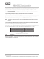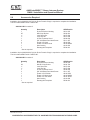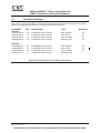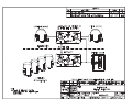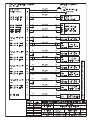
1
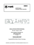
SPECIAL NOTICE
This product is now licensed to Anodyne Electronics Manufacturing (AEM) from Northern
Airborne Technology (NAT). AEM is responsible for all matters related to this product, including
sales, support and repair services.
Please note the transition to convert product manuals and supporting documentation is an
ongoing process and is being addressed on an ‘as needed’ basis.
All references to NAT product part numbers (and associated images) are equivalent to AEM
product part numbers.
Contact info:
Anodyne Electronics Manufacturing Corp.
#15-1925 Kirschner Road
Kelowna B.C. Canada
V1Y 4N7
Email: [email protected]
Toll Free: 1-888-763-1088
Phone: 1-250-763-1088
Fax: 1-250-763-1089
www.aem-corp.com
SM09-1
AA82 InterMUSIC™
Stereo Intercom System
INSTALLATION AND OPERATION MANUAL
REV 2.00 April 16, 2012
Anodyne Electronics Manufacturing Corp.
15-1925 Kirschner Road
Kelowna, BC, Canada.
V1Y 4N7
Telephone (250) 763-1088
Facsimile (250) 763-1089
Website: www.aem-corp.com
© 2012 Anodyne Electronics Manufacturing Corp. (AEM),
All Rights Reserved
CONFIDENTIAL AND PROPRIETARY TO ANODYNE ELECTRONICS MANUFACTURING CORP.
AA82 InterMUSIC™ Stereo Intercom System
SM09-1 Installation and Operation Manual
COPYRIGHT STATEMENT
© 2012 Anodyne Electronics Manufacturing Corp. (AEM), All Rights Reserved
This publication is the property of AEM and is protected by Canadian copyright
laws. No part of this document may be reproduced or transmitted in any form or
by any means including electronic, mechanical, photocopying, recording, or
otherwise, without the prior written permission of AEM.
Installation and Operation Manual
Page ii
ENG-FORM: 820-0100.DOTX
CONFIDENTIAL AND PROPRIETARY TO ANODYNE ELECTRONICS MANUFACTURING CORP.
AA82 InterMUSIC™ Stereo Intercom System
SM09-1 Installation and Operation Manual
Prepared By:
Checked By:
Tony Pearson
Designer
Apr 16, 2012
Approved By:
Tom Betzelt
Product Support
Manager
May 28, 2012
Loen Clement
Designer
May 24/12
The status of this installation and operation manual is controlled by issue shown on the title page. The
status of each section is controlled by revision shown in the footer of each page. All revisions affecting
sections of this manual have been incorporated into the latest issue.
ISSUE/REVISION RECORD
Manual Issue
Number
Section
Revision Number
Revision Description
Issue Date
4.11
Section 1 Rev: 1.00
Section 2 Rev: 1.00
Section 3 Rev: 1.00
Updated Installation Kit Information.
Update to current templates.
Aug 29, 2008
AEM MANUAL REVISIONS
Section
Revision Number
Revision Description
Date
All
Rev 2.00
Updated drawings and template
April 16, 2012
Installation and Operation Manual
Page iii
ENG-FORM: 820-0100.DOTX
CONFIDENTIAL AND PROPRIETARY TO ANODYNE ELECTRONICS MANUFACTURING CORP.
AA82 InterMUSIC™ Stereo Intercom System
SM09-1 Installation and Operation Manual
Table of Contents
Section
Title
1.0
Description
1.1
1.2
1.3
1.4
1.4.1
1.4.2
1.4.3
Introduction
Purpose of Equipment
Design Features
Specifications
Electrical Specifications
Physical Specifications
Environmental Specifications
2.0
Installation
2.1
2.2
2.2.1
2.3
2.4
2.4.1
2.4.2
2.4.3
2.4.4
2.4.5
2.5
2.5.1
2.5.2
2.5.3
2.5.4
2.5.5
2.5.6
2.6
2.7
Introduction
Unpacking and Inspection
Warranty
Continued Airworthiness
Installation Procedures
Warnings
Cautions
Cabling and Wiring
Mounting
Post Installation Checks
Adjustments and Connections
Radio Settings
Setting Up Music and Muting
Setting Balance and Bass Potentiometers
Other ICS Functions
Music Selection (AA82-060 only)
Final Check
Accessories Required
Installation Drawings
3.0
Operation
3.1
3.2
3.3
3.3.1
3.3.2
3.3.3
Introduction
General Information
Controls and Indicators
Stereo & Intercom Special Features
Logic Explanation
Tie/Split Operation
Installation and Operation Manual
Page
1-1
1-1
1-1
1-2
1-2
1-3
1-3
2-1
2-1
2-1
2-1
2-1
2-1
2-2
2-2
2-2
2-3
2-3
2-3
2-4
2-4
2-4
2-5
2-5
2-6
2-7
3-1
3-1
3-1
3-2
3-2
3-2
Page iv
ENG-FORM: 820-0100.DOTX
CONFIDENTIAL AND PROPRIETARY TO ANODYNE ELECTRONICS MANUFACTURING CORP.
AA82 InterMUSIC™ Stereo Intercom System
SM09-1 Installation and Operation Manual
Section 1.0 Description
1.1
Introduction
Information in this section consists of product description, design features and specifications for the AA82
InterMUSIC™ Stereo Intercom System. All derivative product information shall be contained in the
applicable manual supplement, which may be obtained from AEM as required.
Review all notes, warning and cautions.
1.2
Purpose of Equipment
The AA82 InterMusic™ Stereo Intercom System is a system for passenger entertainment and
communications. The system is available in two models, the AA82-001 and AA82-060. The AA82-001 is
compatible with AA80 intercoms and allows four stereo positions. The AA82-060 is compatible with AA83
intercoms and allows six stereo positions. Each is linked via the ICS Tie Line to the crew audio system.
The AA82 InterMUSIC™ Stereo Intercom offers the passengers full control of their intercom and entertainment
functions. The front panel controls permit adjustment of Intercom level, VOX threshold and Music level.
Internal adjustments set Receive level, Receive Balance, ICS balance, ICS bass, Music muting and Music
balance. These controls allow unique features such as making the intercom audio appear to be coming from
the left and receive audio coming from the right, which is helpful in relating the audio to the source. The stereo
audio is muted during intercom operation or when receive audio is detected, permitting greater intelligibility of
in-coming transmissions. A front panel annunciator allows easy visual setting of the VOX threshold and also
indicates RX signal reception.
1.3
Design Features
The AA82 uses surface mount technology and provides true stereo music audio to the headset.
The Inter MUSIC™ system employs NAT’s unique audio processing, which reduces noise and tailors the
frequency response to produce clean, crisp intercom audio.
High output power and low distortion results in better on-board communication and greatly reduces noise
fatigue.
Employing highly integrated stereo audio processors, component numbers were substantially reduced
and product reliability is increased.
With the reduction of component size, more features were incorporated (Adjustable music muting by
intercom and receive audio, bass control of intercom and stereo audio).
Designed into the smallest possible chassis, it allows mounting in the remotest locations usually close to
the passengers).
April 16, 2012 Rev: 2.00
Page 1-1
ENG-FORM: 800-0100.DOTX
CONFIDENTIAL AND PROPRIETARY TO ANODYNE ELECTRONICS MANUFACTURING CORP.
AA82 InterMUSIC™ Stereo Intercom System
SM09-1 Installation and Operation Manual
The AA82’s ICS Tie Line is fully compatible with existing AEM products, making it possible to chain
multiple systems together (3 units max).
The unit has overvoltage and reverse voltage protection to insure operability in severe aircraft
environments.
1.4
Specifications
1.4.1
Electrical Specifications
Input Power
+11 to +32 Vdc
Supply Current
385 mA max. (full output power)
Headset Power
400 mW per channel (total power)
100 mW typical into each headset element (300 Ω/side)
4 headsets (AA82-001)
6 headsets (AA82-060)
Lighting
160 mA at 28 Vdc
600 mA at 5 Vdc
Modes of Operation
Voice track trigger circuit
Adjustable treshold on panel
Live or Hot mic by rotating VOX control counterclockwise
Indicators
Receive monitor (Green LED)
VOX ICS triggered (Amber LED)
Front Panel Controls
ICS Volume
Music Level
VOX Threshold
Internal Side Panel Controls
RX Volume
RX Balance
ICS Balance
Music Balance
Inputs (AA82-001)
output
4 microphone ‘carbon equivalent‘, 250 mVrms for full
150 Ω input inpedance
4 ICS keylines (active ground) for all users
2 music inputs compatible (left & right), configurable for
portable CD/cassette/etc, phones compatible (3 Vp-p)
April 16, 2012 Rev: 2.00
Page 1-2
ENG-FORM: 800-0100.DOTX
CONFIDENTIAL AND PROPRIETARY TO ANODYNE ELECTRONICS MANUFACTURING CORP.
AA82 InterMUSIC™ Stereo Intercom System
SM09-1 Installation and Operation Manual
4 microphone ‘carbon equivalent’, 250 mVrms for full
Inputs (AA82-060)
output,
150 Ω input impedance
6 ICS keylines (active ground) for all users
2 music inputs compatible (left & right), configurable for
either portable CD/cassette, phones compatible (3 Vp-p)
or CD changer Line Out Compatible (100-500 mV @ 10
kΩ)
Inputs (all models)
impedance
1 radio input, 2.5 Vrms for full output, 1 kΩ input
bi-directional ICS Tie Line, 1 Vp-p for full output, 2 kΩ
input impedance
1.4.2
1.4.3
Outputs (AA82-001)
4 aircraft stereo headsets (300 Ω / side)
Note: Not designed for 8 Ώ headsets.
Outputs (AA82-060)
6 aircraft stereo headsets (300 Ω / side)
Note: Not designed for 8 Ω headsets
Logic
ICS and RX audio both muted the music channel
No emergency or transmit functions.
Physical Specifications
Height
1.30” (33.0 mm)
Depth
5.60” (142.2 mm) excluding front panel controls
Width
2.60” (66.0 mm)
Weight
0.6 lbs (283.5 g) excluding external hardware
Mounting
Horizontal or vertical with reversible faceplate for through-panel
mounting
Environmental Specifications
Temperature
-40q C. to +70q C (operating)
-55˚C to +85˚C (storage)
Humidity
95% Non-condensing
Altitude
25,000 feet max
End of Section 1.0
April 16, 2012 Rev: 2.00
Page 1-3
ENG-FORM: 800-0100.DOTX
CONFIDENTIAL AND PROPRIETARY TO ANODYNE ELECTRONICS MANUFACTURING CORP.
AA82 InterMUSIC™ Stereo Intercom System
SM09-1 Installation and Operation Manual
Section 2.0 Installation
2.1
Introduction
Information in this section consists of unpacking and inspection procedures, installation procedures, postinstallation checks and installation drawings for the AA82 InterMUSIC™ Stereo Intercom System.
Review all notes, warnings and cautions.
2.2
Unpacking and Inspection
Unpack the equipment carefully. Inspect the unit visually for damage due to shipping and report all such
claims immediately to the carrier involved. Check that all items listed below are present before proceeding
and report any shortage immediately to your supplier:
2.2.1
AA82 InterMUSIC™ Stereo Intercom System
Product Information Card
Certificate of Conformity or Release Certification
Installation kit with faceplate (crimp type connector)
Warranty
All Anodyne Electronics Manufacturing Corp. (AEM) products are warranted for 2 years. See the website
www.aem-corp.com/warranty for complete details.
2.3
Continued Airworthiness
Maintenance of the AA82 InterMUSIC™ Stereo Intercom System is ‘on condition’ only. Periodic
maintenance of this product is not required.
2.4
Installation Procedures
2.4.1
Warnings
WARNING:
High volume settings can cause hearing damage.
Set the headset volume control to the minimum volume setting prior to
conducting tests, and slowly increase the headset volume to a
comfortable listening level.
April 16, 2012 Rev: 2.00
Page 2-1
ENG-FORM: 805-0100.DOTX
CONFIDENTIAL AND PROPRIETARY TO ANODYNE ELECTRONICS MANUFACTURING CORP.
AA82 InterMUSIC™ Stereo Intercom System
SM09-1 Installation and Operation Manual
2.4.2
Cautions
CAUTION:
DO NOT use mono aircraft headsets in this system. Mono aircraft headsets will
short out one side of the AA82 power amplifier when installed in the stereo jacks.
This may result in eventual unit failure. Use only stereo headsets with this system.
2.4.3
Cabling and Wiring
All wire shall be selected in accordance with the original aircraft manufacturer's Maintenance Instructions
or AC43.13-1B Change 1, Paragraphs 11-76 through 11-78. Unshielded wire types shall qualify to
MIL-W-22759 as specified in AC43.13-1B Change 1, Paragraphs 11-85, 11-86, and listed in Table 11-11.
For shielded wire applications, use Tefzel MIL-C-27500 shielded wire with solder sleeves (for shield
terminations) to make the most compact and easily terminated interconnect. Follow the connector map in
Section 2.7 as required.
Allow 3" from the end of the shielded wiring to the shield termination to allow the connector hood to be
easily installed. Reference the interconnect drawing in Section 2.7 for shield termination details. Note that
the hood is a "clamshell" hood, and is installed after the wiring is complete. Aircraft harnessing shall
permit the unit to be removed from the panel for easy access to all side adjustments. Do NOT mount the
unit until all adjustments have been performed.
Maintain wire segregation and route wiring in accordance with the original aircraft manufacturers
Maintenance Instructions.
Unless otherwise noted, all wiring shall be a minimum of 24 AWG, except power and ground lines, which
shall be a minimum of 22 AWG. Reference the Interconnect drawing for additional specifications. Check
that the ground connection is clean and well secured, and that it shares no path with any electrically noisy
aircraft accessories such as blowers, turn and bank instruments or similar loads. Power to this unit must
be supplied from a separate circuit breaker or fuse (fast blow), and not attached to any other circuit
breaker without additional protection. Verify that the selected circuit breaker size and wire gauge are
adequate for the installation using the techniques specified in AC43.13-1B Change 1, Paragraphs 11-47
through 11-51 and 11-66 through 11-69.
2.4.4
Mounting
The AA82 InterMUSIC™ Stereo Intercom can be mounted in either a vertical or horizontal orientation.
Place the adhesive backed drill template in an appropriate place on the instrument panel and drill through
the indicated locations. The mounting nuts on the faceplate controls should not be removed at any time.
The clearance holes for the nuts should be 3/8" to allow them to fit through the instrument panel. The unit
is secured by three black Phillips screws, which require 5/32" holes.
Notes: 1) The clock mount faceplate used with the AA80 Series is not supplied.
2) Perform all functional tests and adjustments prior to mounting. Secure the unit to the panel
prior to flight.
April 16, 2012 Rev: 2.00
Page 2-2
ENG-FORM: 805-0100.DOTX
CONFIDENTIAL AND PROPRIETARY TO ANODYNE ELECTRONICS MANUFACTURING CORP.
AA82 InterMUSIC™ Stereo Intercom System
SM09-1 Installation and Operation Manual
2.4.5
Post Installation Checks
2.4.5.1
Voltage/Resistance Checks
Do not attach the AA82-xxx until the following conditions are met.
Check the following for the AA82-001:
a) Check pin 1 for +11 to +32 Vdc relative to ground.
b) Check pin 14 for continuity to ground (less than 0.5:).
Check the following for the AA82-060:
a) Check pin 1 for +11 to +32 Vdc relative to ground.
b) Check pin 16 for continuity to ground (less than 0.5:).
2.4.5.2
Power On Checks
Power up the aircraft’s systems and confirm normal operation of all functions of the AA82-xxx. Reference
Section 3 for specific operational details.
a) Check that headsets are installed correctly.
b) To verify proper operation, all functions and levels shall be checked in-flight.
c) Check preset adjustments are completed before aircraft departure.
Upon satisfactory completion of all performance checks, make all required log book entries, electrical
load, weight and balance amendments and other documentation as required by your local regulatory
agency before releasing the aircraft for service.
2.5
Adjustments and Connections
All AA95/AMS4X Audio Controllers used with the AA82 must have the ICS Tie Line and Gain
Modifications installed. This applies to units with a serial number less than 1918.
The AA82-xxx has internal trimpot adjustments accessible through holes in the right and left sides of the
unit. The AA82-060 also has internal jumper settings for music input types. Reference Section 2.5.5 for
jumper settings.
2.5.1
Radio Settings
To achieve correct radio volume settings, check that the headset radio level is acceptable. This
adjustment should be made with the radio volume set to about 50%. Adjust the headset volume control
(if it exists) for something less than full volume, such as 75% (full output on active headsets will give the
worst over-all signal to noise ratio, as it will increase the low level noise floor). Adjust the RX VOL on the
side of the AA82 to a preferred level.
Check that the music is muting at this stage when a radio signal is received. If not, the radio itself set too
low and must be increased at the radio to properly activate the internal muting circuit in the AA82. Once
the radio settings are satisfactory, perform all other adjustments. The RX VOL trimpot sets only the radio
level heard during normal operation and has no effect on any other function, including muting.
April 16, 2012 Rev: 2.00
Page 2-3
ENG-FORM: 805-0100.DOTX
CONFIDENTIAL AND PROPRIETARY TO ANODYNE ELECTRONICS MANUFACTURING CORP.
AA82 InterMUSIC™ Stereo Intercom System
SM09-1 Installation and Operation Manual
2.5.2
Setting Up Muting and Music
Rotate the front panel VOX potentiometer until the VOX indicator is off. The music audio can now be
heard. Adjust the music to a comfortable level with the front panel potentiometer. If the music is louder in
one ear than the other, the side panel MUSIC BAL control may need adjusting, although this could be a
problem with your music source, as this adjustment should be correct from the factory.
With the front panel VOX potentiometer turned fully counter-clockwise (LIVE ICS, the indicator should be
ON), adjust the MUSIC MUTE trimpot to the desired level of music audio in the background. This is the
level the music will default to whenever it is muted and can range from OFF to only slightly muted as
preferred.
2.5.3
Setting Balance and Bass Potentiometers
With the VOX control still in the LIVE ICS position, talk back and forth on the intercom to determine the
voice quality. If more bass is desired, the ICS BASS potentiometer may be adjusted for the preferred
tone. Check that this adjustment is compatible with the headsets and that it does not increase distortion. If
the ICS audio seems distorted, reduce the ICS BASS potentiometer for best results. Some aircraft
headsets do not have very good internal microphone amplifiers and achieve "noise reduction" by shunting
the microphone with a large capacitor to reduce high frequency noise. This may make the voice very bass
heavy and muffled. Best results were obtained in AEM testing with the following headsets:
Bose (may require re-wiring of plug for stereo)
David Clark (may require modification for stereo)
Most aircraft headsets do not do a good job of reproducing wide bandwidth music information, which
seriously compromises the performance of the AA82. AEM will test any headset for system compatibility if
the unit is supplied for evaluation with the AA82.
If you wish the ICS audio to come from a particular location (left to right), adjust the ICS BAL
potentiometer for the desired position.
Note:
If you have not controlled the Left/Right headset jack wiring, it may appear to change locations
between different users.
Set the location to suit your preference, listen to an incoming radio transmission and position it (ideally) in
the opposite location with the RX BAL trimpot. The best setup should give some perceived difference in
location for these two sources (radio & ICS), as it will improve recognition of who is speaking in the
system.
2.5.4
Other ICS Functions
Check all installed functions and check the ICS function for all users. The VOX potentiometer on the front
controls all passengers. Adjust as needed for the best performance.
Note:
Significantly different headsets may have different microphone characteristics, which affect VOX
squelch settings.
Note:
The David Clark M-7 microphone is more active than M-4 or M-1 microphones and may
aggravate headset imbalance if used in a mixed system.
April 16, 2012 Rev: 2.00
Page 2-4
ENG-FORM: 805-0100.DOTX
CONFIDENTIAL AND PROPRIETARY TO ANODYNE ELECTRONICS MANUFACTURING CORP.
AA82 InterMUSIC™ Stereo Intercom System
SM09-1 Installation and Operation Manual
To test KEYED ICS operation of the AA82-060, be sure the VOX potentiometer is set fully clockwise and
all ICS audio is shut off. Keying the ICS switches should activate the specific microphone involved.
Note:
Each microphone is individually gated in the AA82-060 and only the microphone involved with a
key signal is activated.
The front panel indicator should illuminate orange when there is activity on the intercom.
2.5.5
Music Selection (AA82-060 only)
The cover of the unit must be removed in order to access jumper locations. Reference Section 6 for
Exploded View AA82\060\904-0 and Component Locator AA82\060\924-0 drawings.
Note:
The AA82 is a static sensitive device. Use proper ESD handling procedures when the cover is
removed.
To gain access to the jumpers, remove the cover from the AA82. Remove the top PCB by removing the
three pan head screws and carefully lifting it straight up. When reassembling the unit check that the pins
and connector are aligned properly before screwing the PCB down.
The two types of music inputs are configured by the position of jumpers JP101 and JP102, located on the
main PCB near the access hole for Q101. Music input type is determined as shown in Table 1:
Music Input Type
Jumper Positions
Low Z/Portable cassette/CD compatible
JP101 and JP102 Installed
High Z/CD changer compatible
JP101 and JP102 Removed
Table 1
Music Input Type and Jumper Position
2.5.6
Final Check
Before leaving the aircraft, check that the mating connector is securely fastened to the AA82 and the unit
is securely fastened to the aircraft panel.
April 16, 2012 Rev: 2.00
Page 2-5
ENG-FORM: 805-0100.DOTX
CONFIDENTIAL AND PROPRIETARY TO ANODYNE ELECTRONICS MANUFACTURING CORP.
AA82 InterMUSIC™ Stereo Intercom System
SM09-1 Installation and Operation Manual
2.6
Accessories Required
Installation kit p/n AA82-001-IKC (25 pin D-min Female Crimp) is required to complete the installation.
The kit includes AEM Part No. D25SL-IKC.
AA82-001-IKC consists of:
Quantity
1
25
1*
1*
1
3
2
1
1
1
* Use as required.
Description
D-min 25 Socket Housing
MS Crimp Socket
Jack Screw Set
Lock Clip Set
25 Pin Connector Hood
5/8" 6-32 Black Pan Head Screw
Fluted 1/8" Knob
Fluted 1/8" Music Knob
Hole Overlay
Rectangular Faceplate
AEM Part No.
20-21-025
20-26-901
20-27-002
20-27-004
20-29-026
25-11-427
40-18-002
40-18-MUS2
43-10-083
50-04-821
Installation kit p/n AA82-060-IKC (44 pin D-min Female Crimp) is required to complete the installation.
The kit includes AEM Part No. D44SL-IKC.
AA82-060-IKC consists of:
Quantity
1
44
1*
1*
1
3
1
1
1
1
1
* Use as required.
April 16, 2012 Rev: 2.00
Description
D-min 44 Socket Housing
Mini D Crimp Socket
Jack Screw Set
Lock Clip Set
25 Pin Connector Hood
5/8" 6-32 Black Pan Head Screw
Fluted 1/8" ICS Knob
Fluted 1/8" Music Knob
Fluted 1/8" VOX Knob
Hole Overlay
Rectangular Faceplate
AEM Part No.
20-20-044
20-26-703
20-27-002
20-27-004
20-29-026
25-11-427
40-18-ICS2
40-18-MUS2
40-18-VOX2
43-10-080
50-04-821
Page 2-6
ENG-FORM: 805-0100.DOTX
CONFIDENTIAL AND PROPRIETARY TO ANODYNE ELECTRONICS MANUFACTURING CORP.
AA82 InterMUSIC™ Stereo Intercom System
SM09-1 Installation and Operation Manual
2.7
Installation Drawings
Use of the "#" symbol in the REV. column indicates that the document is listed elsewhere in the manual.
Refer to the applicable AEM Part No. to locate the referenced document.
DOCUMENT
AA82-001
AA82\001\302-0
AA82\001\403-0
AA82\001\405-0
AA82\001\921-0
AA82-060
AA82\060\302-0
AA82\060\403-0
AA82\060\405-0
AA82\001\921-0
REV.
DESCRIPTION
TYPE
SERIAL NO.
1.02
1.01
1.01
1.00
InterMUSIC Stereo Intercom
InterMUSIC Stereo Intercom
InterMUSIC Stereo Intercom
InterMUSIC Stereo Intercom
Block Diagram
Interconnect
Connector Map
Mounting Plate
All
All
All
All
1.01
1.31
1.02
#
InterMUSIC Stereo Intercom
InterMUSIC Stereo Intercom
InterMUSIC Stereo Intercom
InterMUSIC Stereo Intercom
Block Diagram
Interconnect
Connector Map
Mounting Plate
All
All
All
Section 2.0 ends following the above documents
April 16, 2012 Rev: 2.00
Page 2-7
ENG-FORM: 805-0100.DOTX
CONFIDENTIAL AND PROPRIETARY TO ANODYNE ELECTRONICS MANUFACTURING CORP.
Confidential and Proprietary to NAT
Confidential and Proprietary to NAT
Confidential and Proprietary to NAT
Confidential and Proprietary to NAT
AA82 InterMUSIC™ Stereo Intercom System
SM09-1 Installation and Operation Manual
Section 3.0 Operation
3.1
Introduction
Information in this section consists of functional and operational procedures for the AA82 InterMUSIC™
Stereo Intercom System.
3.2
General Information
The AA82 is available in two models, the AA82-001 and AA82-060. Both are designed for passenger
entertainment and communications. The AA82-001 is compatible with AA80 series intercom and allows
four stereo positions. The AA82-060 is compatible with AA83 series intercoms and allows six stereo
positions. Each is linked via the bi-directional ICS Tie Line to the crew audio system.
3.3
Controls and Indicators
The front panel controls shown in Figure 1 permit user adjustment of frequently needed signals, such as
Intercom Audio Level (ICS Volume), Microphone VOX Threshold (VOX Squelch) and Music Level
(Musical Note).
ICS Volume
VOX Squelch
Music Volume
Annunciator
Figure 1: Front Panel Controls
Internal adjustments set default values for Receive Audio Level, Receive Balance, ICS Balance, ICS
Bass, Music Muting and Music Balance. These extensive controls allow some unique features, such as
making the intercom and radio sources appear from distinct listening space positions to aid in recognition.
Music Muting allows the dynamic range of the music muting function to be set to suit individual
preferences and Bass adjustments allow tailoring to the exact characteristics of the headsets chosen.
Music muting occurs in a smooth, fast attack/slow return sequence, for maximum comfort and clarity of
communication in all modes.
April 16, 2012 Rev: 2.00
Page 3-1
ENG-FORM: 806-0100.DOTX
CONFIDENTIAL AND PROPRIETARY TO ANODYNE ELECTRONICS MANUFACTURING CORP.
AA82 InterMUSIC™ Stereo Intercom System
SM09-1 Installation and Operation Manual
3.3.1
Stereo & Intercom Special Features
The stereo music audio is muted during intercom operation and when radio receive audio is detected,
permitting greater intelligibility of incoming transmissions. The AA82 Muting adjustment ranges from
complete music muting to gentle background music on command, with a fast attack and slow level return
for optimum user comfort. Each microphone is individually gated for the best possible noise performance
during VOX operation. A front panel annunciator allows easy visual setting of the VOX threshold and also
indicates radio signal reception.
3.3.2
Logic Explanation
When ICS or RX functions are active, any music will be muted quickly as shown in Table 1. The music will
slowly return when transmission is completed. The degree of muting is set at the time of installation. The
relative volume of the music can be changed from the front panel by adjusting the music volume knob
marked with a musical note.
Active: Function being used
Muted: Functions that are overridden by the active condition
Idle:
Functions that are not active, but still available for use
Music
ICS
RX
Active
Idle
Idle
Muted
Active
Idle
Muted
Idle
Active
Muted
Active
Active
Table 1
Music Muting
3.3.3
Tie/Split Operation
The crew audio system that the AA82 is connected to may have a Tie/Split mode of operation. The crew's
Tie/Split switch connects or disconnects the ICS Tie Line from the passengers' intercom system. Intercom
between the passengers is maintained, but they are cut off from the crew ICS and radio audio. Many
different circuit combinations can be set up depending on what device is hooked to the Tie Line.
End of Section 3.0
April 16, 2012 Rev: 2.00
Page 3-2
ENG-FORM: 806-0100.DOTX
CONFIDENTIAL AND PROPRIETARY TO ANODYNE ELECTRONICS MANUFACTURING CORP.