1
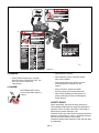
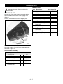
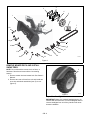
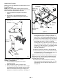
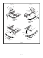
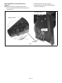
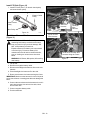
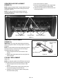
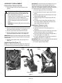
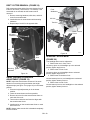
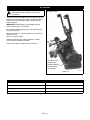
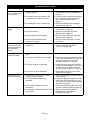
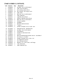
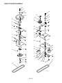
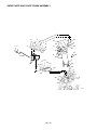
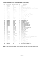
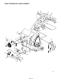
XL Series Snow Thrower
Owner/Operator and Parts Manual
Model
815034
03840800C 1/12
Printed in USA
TABLE OF CONTENTS
Safety . . . . . . . . . . . . . . . . . . . . . . . . . . . . . . . . . . . . . 3
Storage . . . . . . . . . . . . . . . . . . . . . . . . . . . . . . . . . . . 22
Installation . . . . . . . . . . . . . . . . . . . . . . . . . . . . . . . . . 7
Specifications. . . . . . . . . . . . . . . . . . . . . . . . . . . . . . 22
Removal . . . . . . . . . . . . . . . . . . . . . . . . . . . . . . . . . . 13
Troubleshooting . . . . . . . . . . . . . . . . . . . . . . . . . . . . 23
Operation . . . . . . . . . . . . . . . . . . . . . . . . . . . . . . . . . 14
Parts List . . . . . . . . . . . . . . . . . . . . . . . . . . . . . . . . . . 24
Maintenance. . . . . . . . . . . . . . . . . . . . . . . . . . . . . . . 16
Warranty . . . . . . . . . . . . . . . . . . . . . . . . . . . . . . . . . . 33
Service and Adjustments . . . . . . . . . . . . . . . . . . . . 17
INTRODUCTION
THE MANUAL
•
Before operation of unit, carefully and completely read
this Manual and the unit’s Owner/Operator Manual. The
contents will provide you with an understanding of safety
instructions and controls during normal operation and
maintenance.
All reference to left, right, front, or rear are given from
operator sitting in operation position and facing the
direction of forward travel.
MODEL AND SERIAL NUMBERS
Transfer
model & serial
number label
from product
registration
here.
When ordering replacement parts or
making service inquiries, know the
Model and Serial numbers of your
unit.
Numbers are located on the product
registration form in the unit literature
package. They are printed on a serial
number label, located on the frame of
your unit.
Serial Number Label
Record unit model and serial numbers here.
PRODUCT REGISTRATION
The Ariens/Gravely dealer must register the product at
the time of purchase. Registering the product will help the
company process warranty claims or contact you with the
latest service information. All claims meeting
requirements during the limited warranty period will be
honored, whether or not the product registration card is
returned. Keep a proof of purchase if you do not register
your unit.
Customer Note: If the dealer does not register your
product, please fill out, sign, and return the product
registration card to Ariens or go to www.ariens.com or
www.gravely.com.
UNAUTHORIZED REPLACEMENT PARTS
Use only Ariens/Gravely replacement parts. The
replacement of any part on this vehicle with anything
other than an Ariens/Gravely authorized replacement
part may adversely affect the performance, durability, or
safety of this unit and may void the warranty.
Ariens/Gravely disclaims liability for any claims or
damages, whether warranty, property damage, personal
injury or death arising out of the use of unauthorized
replacement parts.
DISCLAIMER
Ariens/Gravely reserves the right to discontinue, make
changes to, and add improvements upon its products at
any time without public notice or obligation. The
descriptions and specifications contained in this manual
were in effect at printing. Equipment described within this
manual may be optional. Some illustrations may not be
applicable to your unit.
Figure 1
OEe013
GB - 2
© Copyright 2012 Ariens Company
DELIVERY
WARNING: Improper assembly or adjustments
can cause serious injury.
Customer Note: If you have purchased this product
without complete assembly and instruction by your
retailer, it is your responsibility to:
1. Read and understand all assembly instructions in
this manual. If you do not understand or have
difficulty following the instructions, contact your
nearest Ariens/Gravely Dealer for assistance. Make
sure all assembly has been properly completed and
safety interlock system works properly.
2. Understand all Safety Precautions provided in the
manuals.
3. Review control functions and operation of the unit.
Do not operate unit unless all controls function as
described in this manual.
4. Review recommended lubrication, maintenance
and adjustments.
5. Fill out a Product Registration Card and return the
card to the Ariens Company or go to
www.ariens.com or www.gravely.com.
NOTE: To locate your nearest Ariens Dealer, go to
www.ariens.com. To locate your nearest Gravely Dealer,
go to www.gravely.com.
SAFETY
SAFETY ALERTS
REQUIRED OPERATOR TRAINING
Look for these symbols to point out
important safety precautions. They mean:
Personal Safety Is Involved!
Original purchaser of this unit was instructed by the seller
on safe and proper operation. If unit is to be used by
someone other than original purchaser; loaned, rented or
sold, ALWAYS provide this manual and any needed
safety training before operation.
Become Alert!
SAFETY DECALS AND LOCATIONS
Obey The Message!
ALWAYS replace missing or damaged safety decals.
See figure 2 for safety decal locations.
Attention!
The safety alert symbols above and signal words below
are used on decals and in this manual.
Read and understand all safety messages.
1. HOT SURFACES!
DO NOT touch parts which
are hot from operation.
ALWAYS allow parts to cool.
DANGER: IMMINENTLY HAZARDOUS
SITUATION! If not avoided, WILL RESULT in
death or serious injury.
077541
WARNING: POTENTIALLY HAZARDOUS
SITUATION! If not avoided, COULD RESULT in
death or serious injury.
2. DANGER!
ROTATING PARTS. Stop
engine and remove ignition key
before clearing.
CAUTION: POTENTIALLY HAZARDOUS
SITUATION! If not avoided, MAY RESULT in
minor or moderate injury. It may also be used to
alert against unsafe practices.
NOTATIONS
NOTE: General reference information for proper
operation and maintenance practices.
IMPORTANT: Specific procedures or information
required to prevent damage to unit or attachment.
PRACTICES AND LAWS
Practice usual and customary safe working precautions,
for the benefit of yourself and others. Understand and
follow all safety messages. Be alert to unsafe conditions
and the possibility of minor, moderate, or serious injury or
death. Learn applicable rules and laws in your area.
Always follow the practices set forth in this manual.
GB - 3
1
2
4
3
OEe010
Figure 2
3. WARNING!
•
Factory wheel weights and / or weight
bucket must be used with Sno-Thro, see
Sno-Thro owner’s manual for
requirements.
•
Read operator’s manual.
•
Allow operation only by a properly trained
adult, never children.
•
Stop engine and remove ignition key prior
to leaving operator’s position for any
reason.
•
Keep all controls, guards and safety
devices properly serviced and functional.
•
Never direct discharge towards persons or
property that may be injured or damaged by
thrown objects.
4. DANGER!
ROTATING PARTS. Keep
clear of auger while engine is
running.
SAFETY RULES
Read, understand, and follow all safety practices in
Owner/Operator Manual before beginning assembly or
operating. Failure to follow instructions could result in
personal injury and/or damage to unit.
ALWAYS remove key and/or wire from spark plug before
assembly, maintenance or service. Unintentional engine
start up can cause death or serious injury.
Complete a walk around inspection of unit and work area
to understand:
GB - 4
• Work area • Your unit • All safety decals
ALWAYS check overhead and side clearances carefully
before operation. ALWAYS be aware of traffic when
operating along streets or curbs.
Keep children and people away. Keep children out of
work area and under watchful care of a responsible adult.
NEVER allow children to operate or play on or near unit.
Be alert and shut off unit if children enter area.
DO NOT allow adults to operate unit without proper
training.
Keep area of operation clear of all toys, pets, and debris.
Thrown objects can cause injury.
Check for weak spots on docks, ramps or floors. Avoid
uneven work areas and rough terrain. Stay alert for
hidden hazards.
Avoid uneven and rough terrain. DO NOT operate near
drop-offs, ditches, or embankments. Unit can suddenly
turn over if a wheel is over the edge of a cliff or ditch, or if
an edge caves in.
Falling snow, fog, etc. can reduce vision and cause an
accident. Operate unit only when there is good visibility
and light.
Only trained adults may operate unit.
Training includes actual operation.
NEVER operate unit after or during the use of
medication, drugs or alcohol. Safe operation requires
your complete and unimpaired attention at all times.
NEVER allow anyone to operate this unit when their
alertness or coordination is impaired.
DO NOT operate unit without wearing adequate winter
outer garments. Wear adequate safety gear, including
safety glasses with side shields, and protective gloves.
Wear proper footwear to improve footing on slippery
surfaces.
DO NOT wear loose clothing or jewelry and tie back hair
that may get caught in rotating parts.
Protect eyes, face and head from objects that may be
thrown from unit. Wear appropriate hearing protection.
Avoid sharp edges. Sharp edges can cut. Moving parts
can cut off fingers or a hand.
ALWAYS keep hands and feet away from all rotating
parts during operation. Rotating parts can cut off body
parts.
NEVER place your hands or any part of your body or
clothing inside or near any moving part while unit is
running.
ALWAYS keep hands away from all pinch points.
DO NOT touch unit parts which might be hot from
operation. Allow parts to cool before attempting to
maintain, adjust or service.
Never direct discharge towards persons or property that
may be injured or damaged by thrown objects. Use
extreme caution on gravel surfaces. Stay alert for hidden
hazards or traffic. Adjust runners so scraper blade does
not contact gravel. DO NOT throw snow any higher than
necessary.
Deflected materials can cause injury and property
damage.
Always stand clear of the discharge area when operating
this unit.
ALWAYS disengage attachment, stop unit and engine,
remove key and allow moving parts to stop before
leaving operator’s position.
ROTATING IMPELLER CAN CAUSE SERIOUS
INJURY. NEVER ATTEMPT TO UNCLOG OR CLEAN
UNIT WHILE ENGINE IS RUNNING.
Read, understand, and follow all instructions in the
manual and on the machine before starting.
Understand:
•
How to operate all controls.
•
The functions of all controls.
•
How to STOP in an emergency.
Before starting engine, disengage control(s).
ALWAYS allow unit and engine to adjust to outdoor
temperatures before clearing snow.
DO NOT overload the machine capacity by attempting to
clear snow at too fast a rate.
DO NOT operate at too fast a rate.
Slow down and turn corners slowly.
Do not operate in reverse unless absolutely necessary.
ALWAYS back up slowly. Always look down and behind
before and while backing.
Disengage attachment drive when travelling from one
work area to another.
Abnormal vibrations are a warning of trouble. Striking a
foreign object can damage unit. Immediately stop unit
and engine. Remove key and wait for all moving parts to
stop. Remove wire from spark plug. Inspect unit and
make any necessary repairs before restart.
Before cleaning, removing clogs or making any
inspections, repairs, etc.: disengage clutch(es), stop unit
and engine, remove key, allow moving parts to stop.
Allow hot parts to cool.
Run unit a few minutes after clearing snow to prevent
freeze-up of attachment.
Disengage attachment when not in use. Disengage all
clutches and place steering levers in neutral before
starting engine. Adjust runners to clear gravel or crushed
rock surfaces safely.
Never leave a running unit unattended. ALWAYS
disengage PTO, lower the attachment, set parking brake,
and shut off engine before leaving unit. ALWAYS remove
key to prevent unauthorized use.
GB - 5
Never carry passengers.
Check clutch and brake operation frequently. Adjust and
service as required. All motion of drive wheels and
auger/impeller must stop quickly when control levers are
released.
DO NOT operate on steep slopes. DO NOT clear snow
across the face of slopes. Keep all movement on slopes
slow and gradual. DO NOT make sudden changes in
speed or direction. Use a slow speed to avoid stops or
shifts on slopes. Avoid starting or stopping on a slope.
DO NOT park unit on a slope unless absolutely
necessary. When parking on a slope always block the
wheels.
ALWAYS shut off engine, remove key, and close fuel
shut-off valve or drain fuel when transporting unit on a
truck or trailer.
Use extra care when loading or unloading unit onto trailer
or truck.
Secure unit chassis to transport vehicle. NEVER secure
from rods or linkages that could be damaged.
DO NOT transport machine while engine is running.
Keep unit free of ice or other debris. Clean up oil or fuel
spills.
This product is equipped with an internal combustion
type engine. DO NOT use unit on or near any
unimproved, forest-covered or brush covered land unless
exhaust system is equipped with a spark arrester
meeting applicable local, state or federal laws. A spark
arrester, if it is used, must be maintained in effective
working order by operator.
Fuel is highly flammable and its vapors are explosive.
Handle with care. Use an approved fuel container.
NO smoking, NO sparks, NO flames. ALWAYS allow
engine to cool before servicing.
NEVER fill fuel tank when engine is running or hot from
operation.
NEVER fill or drain fuel tank indoors.
Replace fuel cap securely and clean up spilled fuel.
Never fill containers inside a vehicle or on a truck or
trailer bed with a plastic liner. Always place containers on
the ground away from your vehicle before filling.
When practical, remove gas-powered equipment from
the truck or trailer and refuel it on the ground. If this is not
possible, then refuel such equipment on a trailer with a
portable container, rather than from a gasoline dispenser
nozzle.
Keep the nozzle in contact with the rim of the fuel tank or
container opening at all times until fueling is complete.
Do not use a nozzle lock-open device.
If fuel is spilled on clothing, change clothing immediately.
Before tipping unit up onto housing, remove fuel so no
spills will occur. Ensure unit is secure and will not tip over
during maintenance.
ALWAYS keep protective structures, guards, and panels
in good repair, in place and securely fastened. NEVER
modify or remove safety devices.
DO NOT change engine governor settings or over-speed
engine.
Fumes from engine exhaust can cause injury or death.
DO NOT run engine in an enclosed area. Always provide
good ventilation.
ALWAYS maintain unit in safe operating condition.
Damaged or worn out muffler can cause fire or explosion.
Keep all hardware properly tightened. Check shear bolts
frequently. Check slip clutch on units so equipped.
Maintain or replace safety and instruction labels, as
necessary.
NEVER store unit with fuel in fuel tank, inside a building
where any ignition sources are present.
Shut off fuel and allow engine to cool completely before
storing in closed area or covering unit.
For extended storage, clean unit thoroughly. See Engine
Manual for proper storage.
Use only attachments or accessories approved by the
manufacturer of the snow thrower such as wheel
weights, counterweights, cabs, etc.
Check components frequently. If worn or damaged,
replace with manufacturer’s recommended parts.
Never operate the snow thrower near glass enclosures,
automobiles, window wells, drop-offs, etc. without proper
adjustment of the snow discharge angle.
Never operate the unit at high transport speeds on
slippery surfaces. Use care when backing up.
Disengage power to the auger / impeller when the snow
thrower is transported or not in use.
Never attempt to make any adjustments while the engine
is running.
GB - 6
INSTALLATION
WARNING: AVOID INJURY. Read and
understand the entire Safety section before
proceeding.
UNPACKING UNIT
On each side of the snow thrower, remove the bracket
that secures the snow thrower to the shipping crate
(figure 3).
Carefully, remove all items from the shipping crate.
Hardware Pack
Item
8
9
10
11
12
13
14
15
16
17
18
19
20
Snow
Thrower
Bracket
Figure 3
OEe040
Package Contents:
Check the contents of your kit for the parts listed below
and shown in figure 4.
Snow Thrower Assembly
Item
1
2
3
4
5
6
7
Description
Snow Thrower
Weight Bracket
Cast Iron Weight
Reflector
Tire and Wheel Assembly
Hot Surface Decal
PTO Belt – HA Raw
Laminated Belt
Qty
1
1
1
2
2
2
1
Ariens P/N
NA
03789051
00172000
00272000
00259000
07754100
07234400
GB - 7
Description
Lift Link
1/2" Trunnion
1-1/4" Flat Steel Washer
#16 Hair Pin
1/2"-13 x 5 Hex Bolt
1/2"-13 Top Locking
Flange Nut
3/8"-16 x 1-1/4 Hex Bolt
3/8"-16 Top Locking
Flange Nut
3/4 x 1 x 5/8 x 1-1/4
Flange Bushing
13/16 x 1-1/2 x 9/64 Flat
Steel Washer
5/32 x 2-15/16 Hair Pin
Right Rear Lift Pivot Pin
Left Rear Lift Pivot Pin
Qty
2
2
5
5
2
2
Ariens P/N
03788900
01590400
06430200
06714900
05962200
06543600
2
2
05958000
06542000
4
05503900
3
06439000
3
1
1
06714000
03838600
03789100
3
2
4
5
1
6
7
20
19
8
18
9
10
17
11
13
16
12
OEe0045
14
15
Figure 4
REMOVE MOWER DECK AND INSTALL
SNOW TIRES
NOTE: Do not discard the mower deck, turf tires, or
hardware. Store these items until the next mowing
season.
5
1. Remove mower deck and mower belt. See Owner’s
Manual.
2. Remove two rear turf tires from unit and install two
snow tire and wheel assemblies (item 5) on unit
(figure 5).
Figure 5
OEe016
Reposition Headlights
IMPORTANT: Make sure optional headlight kits do not
interfere with snow thrower. Turn the headlights down or
remove headlights from unit if they interfere with snow
thrower installation.
GB - 8
Install Snow Thrower
Modify Front Lift Weldment and Attachment Lift
Pedal (Figure 6)
NOTE: Go to Install Snow Thrower Frame on Unit on
page 9 if a 9/16 in. hole is already drilled through the left
front lift weldment and attachment lift pedal.
Flat washer.
Existing
bushing.
Left rear lift
bracket.
Lift link, flat
washer, and
hair pin.
1. Place the attachment lift pedal in the lowest
position.
2. Drill a 9/16 in. hole through the left front lift
weldment and attachment lift pedal as shown in
figure 6.
Left Front Lift
Weldment
Existing
bushing.
Flat washer.
2-1/8 in.
(5.4 cm)
Right rear lift
bracket.
Existing
bushing.
Retaining ring.
Figure 7
4. Connect the snow thrower frame to the left side of
the unit with two 3/4 x 1 x 5/8 x 1-1/4 flange
bushings (item 16), left rear lift pivot pin (item 20),
two 13/16 x 1-1/2 x 9/64 flat steel washers (item 17)
and 5/32 x 2-15/16 hair pins (item 18). See figure 8.
Attachment
Lift Pedal
5. Connect the snow thrower frame to the right side of
the unit with two 3/4 x 1 x 5/8 x 1-1/4 flange
bushings (item 16), right rear lift pivot pin (item 19),
one 1-1/4" flat steel washer (item 10) and #16 hair
pin (item 11), and one 13/16 x 1-1/2 x 9/64 flat steel
washer (item 17) and 5/32 x 2-15/16 hair pin
(item 18). See figure 8.
2-1/8 in.
(5.4 cm)
6. Install 1/2" trunnions (item 9) on lift links (item 8).
7. Install a lift link (item 8) on front lift weldment and on
the lift pedal with 1-1/4" flat steel washer (item 10)
and #16 hair pin (item 11). See figure 8.
4-1/32 in.
(10.2 cm)
Figure 6
NOTE: Turn 1/2" trunnion (item 9) clockwise or counter
clockwise until 1/2" trunnion (item 9) aligns with snow
thrower frame. Always make sure the link is threaded
completely into the trunnion.
OEe020
Install Snow Thrower Frame on Unit
(Figure 7 and Figure 8)
8. On each side of the unit connect 1/2" trunnion
(item 9) to the snow thrower frame with 1-1/4" flat
steel washer (item 10) and #16 hair pin (item 11).
See figure 8.
1. Set the attachment lift pedal to the lowest
attachment height.
2. Slide snow thrower (item 1) under the unit.
3. Remove retaining rings, flat washers, left and right
rear lift brackets and four bushings from the frame.
Save the lift brackets, lift linkages, bushings and
hardware to reinstall the mower deck. See figure 7.
GB - 9
Right Rear
11
10
17
Left Rear
18
18
16
17
16
16
20
16
19
17
Snow Thrower
Frame
18
Snow Thrower
Frame
10
11
10
11
8
8
10
11
9
9
10
11
Right Front
Left Front
Figure 8
GB - 10
2. Install skid shoes as shown in figure 9.
Place Skid Shoes in Operating Position
(Figure 9)
3. Adjust skid shoes (see Skid Shoe Adjustment
(Figure 14) on page 17).
NOTE: The skid shoes are shipped upside down.
1. Remove mounting hardware and skid shoes from
snow thrower.
Operating Position
Shipping Position
Mounting
Hardware
OEe040
Skid Shoe
Figure 9
GB - 11
OEe029
Install PTO Belt (Figure 10)
1. Install PTO belt (item 7) on electric clutch pulley
and snow thrower pulley.
7
Electric Clutch
Pulley
Snow Thrower
Pulley
Main Wire
Harness
Idler Pulley
Figure 10
Headlight
Wire
Harness
OEe022
Snow Thrower
Wire Harness
Install Snow Thrower Wire Harness
(Figure 11)
WARNING: Avoid Electric Shock. Objects
contacting both battery terminals at the same
time may result in injury and unit damage. DO
NOT reverse battery connections.
Explosive Gases from battery can cause death
or serious injury. Poisonous battery fluid
contains sulfuric acid and its contact with skin,
eyes or clothing can cause severe chemical
burns.
Route Snow Thrower Wire
Harness Along the Frame
WARNING: NO flames, NO sparks, NO smoking
near battery.
1. Lift up seat.
2. Disconnect negative battery cable.
3. Disconnect headlight wire harness from main wire
harness.
4. Place headlight wire harness off to the side.
5. Route snow thrower wire harness along the frame.
IMPORTANT: Make sure the harness is clear of all pinch
points, hot surfaces or rotating parts that can damage the
wires.
6. Connect the snow thrower wire harness to the unit’s
main wire harness, blue wire to blue wire, black
wire to black wire.
7. Connect negative battery cable.
8. Put the seat down.
GB - 12
Figure 11
OEe023
INSTALL COUNTERWEIGHTS
5. Install two hot surface decals (item 6) on unit.
(Figure 12)
6. Install two reflectors (item 4) on cast iron weight
(item 3).
WARNING: ALWAYS install counterweights
before operating unit with snow thrower
attached. ALWAYS remove counterweights
when snow thrower is removed from unit.
14
4
12
2
WARNING: Each counterweight weighs 56 lb
(25.54 kg) for a combined total weight of 112 lb
(50.8 kg).
13
1. Position the weight bracket (item 2) in the center of
the rear frame rail so the two 1/2" mounting holes
align with the holes in the rear frame rail. Use
weight bracket as a template to lay out two 7/16"
mounting holes in the top of rear frame rail.
3
6
2. Drill two 7/16" holes through the upper frame rail as
shown in figure 12.
3. Install the weight bracket (item 2) on the rear frame
rail with two 3/8"-16 x 1-1/4 hex bolts (item 14) and
3/8"-16 top locking flange nuts (item 15).
13
15
15
OEe060
Figure 12
4. Install the two cast iron weights (item 3) on weight
bracket (item 2) with two 1/2"-13 x 5 hex bolts
(item 12) and 1/2"-13 top locking flange nuts
(item 13). The bolts go through the weights, weight
bracket and frame.
REMOVAL
3. Disconnect the snow thrower wire harness from the
main wire harness (see figure 11 on page 12).
WARNING: AVOID INJURY. Read and
understand the entire Safety section before
proceeding.
4. Remove snow thrower wire harness from unit.
5. If installed, connect the headlight wire harness to
the main wire harness (see figure 11 on page 12).
WARNING: ALWAYS install counterweights
before operating unit with snow thrower
attached. ALWAYS remove counterweights
when snow thrower is removed from unit.
IMPORTANT: Connect the blue wire from the headlight
wire harness to the blue wire on the main wire harness
and connect the black wire from the headlight wire
harness to the black wire on the main wire harness.
1. Remove counterweights (see figure 12 on
page 13).
IMPORTANT: Make sure the headlight wire harness is
placed away from any moving parts.
6. Remove PTO belt from electric clutch pulley and
snow thrower pulley (see figure 10 on page 12).
WARNING: Avoid Electric Shock. Objects
contacting both battery terminals at the same
time may result in injury and unit damage. DO
NOT reverse battery connections.
IMPORTANT: Ensure the snow thrower wire harness has
been disconnected from the unit before removing the
snow thrower.
Explosive Gases from battery can cause death
or serious injury. Poisonous battery fluid
contains sulfuric acid and its contact with skin,
eyes or clothing can cause severe chemical
burns.
7. Remove snow thrower from unit (see figure 8 on
page 10).
8. Readjust the headlights (see Reposition Headlights
on page 8).
9. Remove snow tires and install two rear turf tires
(see figure 5 on page 8).
WARNING: NO flames, NO sparks, NO smoking
near battery.
2. Disconnect the negative battery cable.
10. Install mower deck and mower belt. See Owner’s
Manual.
GB - 13
OPERATION
WARNING: AVOID INJURY. Read and
understand the entire Safety section before
proceeding.
CONTROLS AND FEATURES
1
2
3
4
5
6
15
7
14
8
13
9
12
10
11
7
OEe024
Figure 13
9. Headlight – Provides illumination for throwing snow
at night.
1. PTO – Engages the auger.
2. Chute Crank – Rotates the chute and changes the
direction of the snow being discharged.
3. Chute Deflector Lever – Controls the chute deflector
and changes the height of the snow being
discharged.
4. Chute – Controls the direction of the snow being
discharged.
10. Scraper Blade – Allows better contact with the
surface being cleared and prevents damage to the
snow thrower housing.
11. Skid Shoe – Controls the amount of clearance
between the scraper blade and the ground.
12. Attachment Lift Pedal – Raises and lowers the snow
thrower.
5. Chute Deflector – Controls the height of the snow
being discharged.
13. Height Adjustment Pin – Adjusts the height of the
snow thrower.
6. Snow Thrower – Throws snow.
7. Drift Cutter – Extends the width of the snow thrower
from 42 inches to 46 inches (1.06 meters to 1.16
meters).
14. Snow Tire – Allows for better snow and ice traction.
15. Counterweight – Provides stability and added weight
for improved traction.
8. Auger – Feeds snow to the impeller and chute to be
discharged.
GB - 14
BEFORE EACH USE
6. Choose the direction and height of snow discharge.
• Use the chute crank to control the direction of
snow discharge.
WARNING: Safety interlock failure and improper
operation of unit can result in death or serious
injury. Check safety interlock system before
each use to make sure it is functioning properly.
• Use the chute deflector lever to control the height
of snow discharge.
NOTE: Disengage the PTO to disengage the auger.
1. Check the safety interlock system of the unit. See
Owner’s Manual.
2. Check snow thrower parts for wear, deterioration, or
damage.
3. Make sure counterweights are installed.
IMPORTANT: DO NOT operate snow thrower without the
counterweights. If the counterweights need to be
installed, go to Install Counterweights on page 13.
4. Make sure all hardware is tight.
5. Make sure auger is clear of ice and snow.
6. Make sure skid shoes are adjusted properly (see
Skid Shoe Adjustment (Figure 14) on page 17).
STARTING THE SNOW THROWER
IMPORTANT: Use oil recommended in the Engine
Manual for cold weather operation.
1. Start engine according to instructions in the unit’s
operator’s manual, and allow the engine to
warm-up for 3 – 5 minutes.
2. Pull up the PTO switch to engage the auger and
throw snow.
STOPPING THE SNOW THROWER IN AN
EMERGENCY
Shut off the PTO, bring steering levers back to neutral,
turn off the engine, and set the parking brake.
SNOW REMOVAL
WARNING: NEVER direct discharge towards
bystanders or windows. DO NOT allow anyone
in front of the snow thrower while operating the
unit.
IMPORTANT: Make sure that the auger is clear of ice
and snow prior to starting the engine.
NOTE: See Operating Tips on page 15 prior to clearing
snow.
OPERATING HEADLIGHTS
Turn ignition switch to the headlight position to turn on
the headlights. Turn ignition switch to the run position to
turn off the headlights.
OPERATING TIPS
Snow is best removed as soon as possible after a snow
fall.
DO NOT use the snow thrower to push snow.
To clear an area, run unit in an overlapping series of
paths. For large areas; start in the middle and throw
snow to each side, so snow is not cleared more than
once.
ALWAYS direct snow away from area to be cleared and
with direction of the wind.
Before removing snow, clear the area of any debris that
might be caught in the auger.
For maximum snow removal and discharge, maintain a
high engine r.p.m. (full throttle) and operate at a slow
ground speed.
For deep snow, drive forward into the snow and stop
forward travel until the auger clears the snow. Repeat
this method until a path is cleared out. On the second
pass, overlap the first path enough to allow the snow
thrower to throw snow without repeated stopping and
starting.
For extremely deep snow, raise the snow thrower as high
as possible to remove the top layer of snow. Drive
forward only until the front tires reach the uncleared
bottom layer of snow and wait until the auger clears the
snow. Reverse the unit and lower the snow thrower to the
ground. Drive forward until the snow again becomes too
deep. Repeat this process until the snow is cleared.
If snow thrower becomes clogged with snow or other
debris. SHUT OFF the engine immediately, wait for all
moving parts to stop, and clear the snow thrower.
1. Warm-up the engine and transmission (see Starting
the Snow Thrower on page 15).
2. Lower the snow thrower.
3. Place throttle lever at full throttle.
4. Pull up the PTO switch to engage the auger.
IMPORTANT: DO NOT overload snow thrower capacity
by attempting to clear snow at too fast a rate. Use a slow
speed to clear deep or hard packed snow.
5. Choose an appropriate ground speed.
GB - 15
MAINTENANCE
WARNING: AVOID INJURY. Read and
understand the entire Safety section before
proceeding.
Interval
Before Each
Use
After Each
Use
Ariens/Gravely Dealers will provide any service or
adjustments which may be required to keep your unit
operating at peak efficiency.
Task
Check Fasteners
Action
•
Check mounting hardware that attaches the snow thrower to the
unit and all other fasteners.
•
Check shear bolts for damage. Replace any shear bolt(s) that are
damaged (see Shear Bolt Replacement on page 18).
•
Replace fasteners that are missing or damaged. Tighten all nuts
and bolts to the correct torque value.
Check Scraper Blade
Check scraper blade for wear. Replace scraper blade if scraper blade
has worn to the point that the snow thrower housing will soon be
touching the ground. See Scraper Blade Replacement on page 18 to
replace the scraper blade.
Check Skid Shoes
Check skid shoes for proper adjustment and for wear. Replace skid
shoes if there is excessive wear. See on page 17 to adjust or replace
the skid shoes.
Clean Snow Thrower
Remove ice and snow from snow thrower and unit.
Every Season Check Auger Belt
Check PTO Belt
Lubricate Snow Thrower
Check Auger belt for wear or damage; replace if necessary (see Auger
Belt Replacement on page 19).
Check PTO belt for wear or damage; replace if necessary (see PTO Belt
Replacement on page 18).
•
Oil the base of the lower chute where it rotates on the chute
adapter. See item 31 and 36 in the Snow Chute and Chute Crank
Assembly illustration on page 28.
•
Oil the pivot point on the upper chute and lower chute. See item 22
and 31 in the Snow Chute and Chute Crank Assembly illustration
on page 28.
•
Oil the bushings that hold the chute crank to the chute crank
bracket. See item 16 in the Snow Chute and Chute Crank
Assembly illustration on page 28.
•
Oil the chute deflector cables. See item 23 and 24 in the Snow
Chute and Chute Crank Assembly illustration on page 28.
•
Oil any other pivot points.
GB - 16
SERVICE AND ADJUSTMENTS
WARNING: AVOID INJURY. Read and
understand the entire Safety section before
proceeding.
SKID SHOE ADJUSTMENT OR
REPLACEMENT
Skid Shoe Adjustment (Figure 14)
Skid shoes control the amount of clearance between the
scraper blade and the ground and should be adjusted as
conditions require.
IMPORTANT: Allow 1/8 in. (3 mm) between scraper
blade and hard smooth surfaces. Allow 1-1/4 in (30 mm)
between scraper blade and uneven or gravel surfaces.
Mounting
Hardware
1. Place snow thrower on a hard level surface.
2. Place a spacer with the appropriate thickness under
each end of scraper blade.
NOTE: Adjust both skid shoes to the same height to keep
the snow thrower and scraper blade level.
3. Loosen mounting hardware and adjust skid shoes
up or down. Tighten mounting hardware.
Skid Shoe Replacement (Figure 14)
NOTE: Replace skid shoes if there is excessive wear.
Always replace both skid shoes at the same time.
Skid Shoe
NOTE: For part numbers of the skid shoe and mounting
hardware go to Snow Thrower and Auger Assembly on
page 30.
1. Place snow thrower on blocks.
2. Remove mounting hardware and skid shoes from
snow thrower. Discard skid shoes.
3. Install new skid shoes on snow thrower with
mounting hardware.
GB - 17
Figure 14
OEe029
SCRAPER BLADE REPLACEMENT
(FIGURE 15)
1. Place snow thrower on blocks.
2. Remove mounting hardware and scraper blade
from snow thrower. Discard scraper blade.
NOTE: Replace scraper blade if scraper blade has worn
to the point that the snow thrower housing will soon be
touching the ground.
3. Install new scraper blade on snow thrower with
mounting hardware.
NOTE: For part numbers of the scraper blade and
mounting hardware go to Snow Thrower and Auger
Assembly on page 30.
Shear Bolt
Mounting Hardware
Scraper Blade
Mounting Hardware
OEe030
Figure 15
SHEAR BOLT REPLACEMENT
(FIGURE 15)
PTO Belt
Electric Clutch
Pulley
IMPORTANT: The auger has shear bolts and locknuts
that are designed to shear if a foreign object or ice jams
the auger.
NOTE: For part numbers of the shear bolts and locknuts,
see items 5 and 12 in the Snow Thrower and Auger
Assembly illustration on page 30.
Snow Thrower
Pulley
1. Shut off engine and lower snow thrower to the
ground.
Idler Pulley
Figure 16
2. Replace the shear bolt(s) and lock nut(s) that has
been damaged.
PTO BELT REPLACEMENT
(Figure 16)
NOTE: For the part number of the PTO belt, see item 10
in the Reduction Drive Assembly illustration on page 26.
1. Shut off engine and lower snow thrower to the
ground.
2. Remove PTO belt from electric clutch pulley and
snow thrower pulley. Discard PTO belt.
3. Install the new PTO belt on electric clutch pulley
and snow thrower pulley.
GB - 18
OEe022
AUGER BELT REPLACEMENT
IMPORTANT: If the drift cutters are installed, the snow
thrower can be placed in the storage position (see
figure 24 on page 22) to replace the auger belt. If drift
cutters are not installed, DO NOT place snow thrower in
the storage position to replace the auger belt.
Remove Snow Thrower from Unit
1. Shut off engine and lower snow thrower to the
ground.
1. Remove finger guard from snow thrower.
WARNING: Avoid Electric Shock. Objects
contacting both battery terminals at the same
time may result in injury and unit damage. DO
NOT reverse battery connections.
2. Pull back idler and remove auger belt from drive
pulley.
3. Remove auger belt from guide pulleys and auger
pulley. Discard auger belt.
Explosive Gases from battery can cause death
or serious injury. Poisonous battery fluid
contains sulfuric acid and its contact with skin,
eyes or clothing can cause severe chemical
burns.
4. Install new auger belt on auger pulley and drive
pulleys.
WARNING: NO flames, NO sparks, NO smoking
near battery.
5. Pull back on idler and install new auger belt on
drive pulley. Slowly release idler until idler rests
firmly against the new auger belt.
Install Snow Thrower on Unit
2. Disconnect the negative battery cable.
1. Slide snow thrower under unit.
3. Disconnect the snow thrower wire harness from the
main wire harness (see figure 11 on page 12).
2. Install snow thrower on unit (see figure 8 on
page 10).
4. Remove snow thrower wire harness from unit.
3. Install PTO belt on electric clutch pulley and snow
thrower pulley (see figure 16 on page 18).
5. Remove PTO belt from electric clutch pulley and
snow thrower pulley (see figure 16 on page 18).
4. Route snow thrower wire harness through hole in
frame (see figure 11 on page 12).
IMPORTANT: Make sure the snow thrower wire harness
has been disconnected from the unit before removing the
snow thrower.
5. Connect snow thrower wire harness to main wire
harness (see figure 11 on page 12).
IMPORTANT: Make sure the snow thrower wire harness
is placed away from any moving parts.
6. Remove snow thrower from unit (see figure 8 on
page 10).
6. Connect negative battery cable.
Replace Auger Belt (Figure 17)
NOTE: For the part number of the auger belt, see item 27
in the Reduction Drive Assembly illustration on page 26.
Auger Pulley
Drive
Pulley
Guide
Pulley
Idler
Auger Belt
Finger Guard
Figure 17
GB - 19
Auger Belt
OEe020
DRIFT CUTTER REMOVAL (FIGURE 18)
Drift cutters extend the width of the snow thrower from 42
inches to 46 inches (1.06 meters to 1.16 meters). If the
extra width is not needed, the drift cutters can be
removed.
1. Remove mounting hardware, skid shoe, and drift
cutter from snow thrower.
Front
Weldment
Lift Link
2. Install skid shoe on snow thrower with mounting
hardware.
Trunnion
3. Repeat steps 1 and 2 for the opposite side.
Snow Thrower
Frame
Mounting
Hardware
Drift
Cutter
Figure 19
Skid
Shoe
OEe033
HEADLIGHT ADJUSTMENT
(FIGURE 20)
The headlight beam can be adjusted to:
1. Shine further out in front of unit.
Loosen top pivot nut, tilt headlight up to the selected
position, tighten top pivot nut.
2. Shine closer in front of unit.
Mounting
Hardware
Figure 18
OEe029
SNOW THROWER CLEARANCE
ADJUSTMENT (FIGURE 19)
NOTE: Adjust the snow thrower clearance if the snow
thrower is not touching the ground when the height
adjustment pin (see figure 13 on page 14) is in the lowest
position.
Loosen top pivot nut, tilt headlight down to selected
position, tighten top pivot nut.
3. Shine further to the side of unit.
Loosen bottom pivot nut, turn headlight out to selected
position, tighten bottom pivot nut.
4. Shine closer to side of unit.
Loosen bottom pivot nut, turn headlight in to the selected
position, tighten bottom pivot nut.
1. Place the height adjustment pin in the lowest
position.
2. Lower the snow thrower as far as possible.
3. Remove trunnion from the snow thrower frame on
each side of the unit.
4. Turn trunnion clockwise until trunnion aligns with
the snow thrower frame.
5. Install trunnion on the snow thrower frame on each
side of the unit.
NOTE: Always make sure the link is threaded completely
into the trunnion.
GB - 20
CHUTE DEFLECTOR CABLE ADJUSTMENT
Headlight
(Figure 22)
NOTE: Adjust the chute deflector cables if the chute
deflector does not move up or down properly.
1. Loosen adjustment nuts.
2. Turn adjustment barrel on each chute deflector
cable until chute deflector cables are taunt.
3. Tighten adjustment nuts.
Adjustment Nut
Chute
Deflector
Cable
Top Pivot Nut
Bottom Pivot Nut
Figure 20
OEe034
CHUTE CRANK ADJUSTMENT
(Figure 21)
NOTE: Adjust the chute crank if the chute does not turn
when using the chute crank.
1. Loosen mounting hardware on chute crank bracket.
2. Slide chute crank bracket towards the chute until
the chute crank fits into the chute crank slot as
shown in figure 21.
Adjustment
Nut
3. Tighten mounting hardware on chute crank bracket.
Chute
Crank Slot
Chute Crank
Chute
Adjustment
Barrel
Figure 22
OEe036
CHUTE DEFLECTOR ADJUSTMENT
(Figure 23)
NOTE: Adjust the chute deflector if the chute deflector
does not stay in the selected position.
To adjust, tighten mounting hardware until the chute
deflector holds the selected position.
Chute
Deflector
Mounting
Hardware
Slots
Chute Crank
Bracket
Figure 21
Figure 23
OEe035
GB - 21
OEe037
STORAGE
WARNING: AVOID INJURY. Read and
understand the entire Safety section before
proceeding.
Storage Position
If the drift cutters are installed, the snow thrower can be
placed in the storage position (figure 24). NEVER place
snow thrower in the storage position without the drift
cutters installed.
IMPORTANT: NEVER spray unit with high-pressure
water. DO NOT store unit outdoors.
Clean plastic surfaces with sponge and mild detergent.
Dry with a soft cloth.
Remove all snow, ice, salt, dirt, grease, etc. from snow
thrower and unit.
Store in a clean, dry area.
Ensure all fasteners are properly tightened. Inspect
moving parts for damage and wear.
Touch up all rusted or chipped painted surfaces.
Only place snow
thrower in the
Storage Position if
the drift cutters
are installed.
Figure 24
SPECIFICATIONS
Model
815034
Serial Number
> 101
Clearing Width with Drift Cutter – in. (m)
46 (1.16)
Clearing Width without Drift Cutter – in. (m)
42 (1.06)
GB - 22
OEe030
TROUBLESHOOTING
Problem
The headlights do not
turn on or shine in the
wrong direction.
Probable Cause
Correction
1. The ignition switch is not turned to the
headlight position.
1. Turn ignition switch to the headlight
position (see Operating Headlights on
page 15).
2. The snow thrower wire harness is not
connected to the main wire harness.
2. Connect the snow thrower wire harness
to the main wire harness (see Install
Snow Thrower Wire Harness on
page 12).
3. The headlights are out of adjustment.
3. Adjust the headlights (see Headlight
Adjustment on page 20).
1. Auger belt is broken.
1. Replace auger belt (see Auger Belt
Replacement on page 19).
2. PTO belt is broken.
2. Replace PTO belt (see PTO Belt
Replacement on page 18).
3. Shear bolt(s) have been sheared.
3. Replace shear bolt(s) (see Shear Bolt
Replacement on page 18).
4. Operator presence switch is not
depressed or is faulty.
4. See unit’s Owner’s Manual or contact
your dealer.
Snow thrower does not
touch the ground with
the height adjustment
pin in the lowest
position.
1. Snow thrower clearance is out of
adjustment.
1. Adjust snow thrower clearance (see Snow
Thrower Clearance Adjustment
(Figure 19) on page 20).
Chute does not rotate
or is hard to rotate.
1. Chute and / or chute crank is frozen in
place.
1. Thaw out chute and / or chute crank.
2. The chute crank needs to be lubricated.
2. Oil the bushings that hold the chute crank
to the chute crank bracket. See item 16 in
the Snow Chute and Chute Crank
Assembly illustration on page 28.
3. The chute needs to be lubricated.
3. Oil the base of the lower chute where it
rotates on the chute adapter. See item 31
and 36 in the Snow Chute and Chute
Crank Assembly illustration on page 28.
4. Chute crank is out of adjustment.
4. Adjust chute crank (see Chute Crank
Adjustment on page 21).
1. Chute deflector cable(s) and / or chute
deflector is frozen in place.
1. Thaw out chute deflector cable(s) and / or
chute deflector.
2. The chute deflector needs to be
lubricated.
2. Oil the pivot point on the upper chute and
lower chute. See item 22 and 31 in the
Snow Chute and Chute Crank Assembly
illustration on page 28.
3. Chute deflector cable(s) are out of
adjustment.
3. Adjust chute deflector cables (see Chute
Deflector Cable Adjustment on page 21).
4. Chute deflector mounting hardware is not
tight enough.
4. Tighten chute deflector mounting
hardware (see Chute Deflector
Adjustment on page 21).
Auger does not
engage.
Chute deflector does
not operate properly.
GB - 23
PARTS LIST
FRAME ASSEMBLY
23
17
25
22
4
18
23
26
22
28
19
23
15
2
22
4
26
16
3
16
20
4
24
4
18
5
6
17
16
19
6
15
14
2
27
7
3
5
4
13
21
1
8
9
10
4
12
4
4
10
9
4
11
OEe001
GB - 24
FRAME ASSEMBLY (CONTINUED)
Item
Part No.
Qty.
1
2
3
4
5
6
7
8
9
10
11
12
13
14
15
16
17
18
19
20
21
22
23
24
25
26
27
28
05958400
03788751
06536300
06542000
00264551
05957800
00260351
00263751
00263651
05948700
00266151
02463600
00264451
01590400
06430200
06714900
05958400
03788851
03788651
03788900
06223600
06714000
06439000
03838600
03789100
05503900
03967500
04446351
4
2
4
23
8
4
1
1
2
9
1
2
1
2
5
5
4
2
2
2
2
3
3
1
1
4
2
1
Description
Hex Bolt, .38-16 x 2.50 Grade 5
Plate, Sno-Thro Mount
Nut, Locking, Center .50-13
Nut, Locking, Top, Flange .38-16
Plate, Shim
Bolt, Hex .38-16 x 3.00 Grade 5
Plate, Subframe
Light-Bar, Snow Throw
Support, Light-Bar, Snow Throw
Bolt, Hex .38-16 x 1.00 Grade 5
Gusset, Light-Bar
Headlight
Bracket, Deflector Control
Trunnion
Washer, Flat Steel .531 x 1.250 x .100
External Hair Pin – #16 Black Zinc
Hex Bolt, .38-16 x 2.5 Grade 5
Pivot Bracket
Weldment, Sub-Frame Tube
Lift Link
Bolt, Round Head Square Neck .38-16 x 1.00 Grade 5
Pin, Hair Int. .15 x 2.937
Washer, Flat Steel .812 x 1.50 x .135
Pin, Right Rear Lift Pivot
Pin, Left Rear Lift Pivot
Bushing, .75 x 1.00 x .625 x 1.25 Flange
Tube, Anti-Crush
Plate, Subframe Top
GB - 25
REDUCTION DRIVE ASSEMBLY
1
2
3
16
4
17
15
5
18
37
14
19
36
6
20
18
12
35
8
34
21
33
11
13
11
32
31
6
7
22
22
23
22
8
21
30
12
24
17
9
25
29
3
22
2
26
1
27
17 33 28
10
OEe003
GB - 26
REDUCTION DRIVE ASSEMBLY (CONTINUED)
Item
Part No.
Qty.
1
2
3
4
5
6
7
8
9
10
11
12
13
14
15
16
17
18
19
20
21
22
23
24
25
26
27
28
29
30
31
32
33
34
35
36
37
05946800
06308400
06446300
06530400
07307000
06444200
00269200
03685300
00169400
07227400
06215700
06543100
06606000
62422300
05962900
05900002
06441900
05518400
08815100
00269451
06537200
05516400
09215200
07324100
00473500
05500039
07224300
06223800
05962200
08300507
06307300
06537300
06519700
08300512
06534900
07300028
06436200
2
2
2
3
1
6
1
2
1
1
4
4
2
1
1
1
3
2
1
1
2
4
1
1
1
2
1
1
1
1
1
1
2
1
1
1
1
Description
Bolt, Hex .25-20 x .75 Grade 5
Washer, Locking .25 x .062 Regular
Washer, Flat Steel .344 x 1.125 x .135
Nut, Spin Lock Flange .312-18
Pulley, V 9.0 x 1.25
Washer, Flat Steel .755 x 1.25 x .125
Shaft, Zoom Snow Throw
Bearing, 2 Bolt Flange.75 ID
Sheave, Blower- 4.25 Diameter
Belt, HA Raw Laminated (Engine clutch to snow thrower drive pulley.)
Bolt, Round Head Square Neck .31-18 x .75 Grade 5
Nut, Locking Top Flange .31-18
Key, Square .187 x .50 x .187 Hardened
Hub Assembly
Bolt, Hex .38-16 x 2.25 Grade 5
Bolt, Hex .50-13 x 7.00
Washer, Flat Steel .531 x 1.06 x .095
Bushing, Nylon, Flange .762 x 1.0 x .580 x 1.48
Bushing, Steel .560 x .745 x 2.04 Steel
Weldment, Idler
Nut, Locking Jam Center .375-16
Bushing, Sleeve .500 x .750 x 1.560
Bushing, .516 x 1.0 x 1.05
Idler Flanged 3.50
Weldment, Idler
Bushing, Flanged 0.75 x 0.875 x .625 x 1.125
V-Belt, HA Raw Edge Laminated
Bolt, Round Head Square Neck .38-16 x 1.75 Grade 5
Bolt, Hex .50-13 x 5.00 Grade 5
Spring, Extension
Washer, Locking .50 x .125
Nut, Hex .50-13
Nut, Locking Center Jam .500-13
Spring, Extension
Nut, Locking Jam Center .375-16
Idler, Flange .38ID x 3.50
Washer, Flat Steel .406 x .812 x .065
GB - 27
SNOW CHUTE AND CHUTE CRANK ASSEMBLY
4
1 2
5
6 7
3
23
22
24
9
34
8
25
9
9
26
33
11
10
27
28
4
13
32 31
17
12
15 16
18
19 16
14
29
30
35
11
28
35
36
28 11
20
21
39
37
39
35
28
38
11
38
GB - 28
OEe005
SNOW CHUTE AND CHUTE CRANK ASSEMBLY (CONTINUED)
Item
1
2
3
4
5
6
7
8
9
10
11
12
13
14
15
16
17
18
19
20
21
22
23
24
25
26
27
28
29
30
31
32
33
34
35
36
37
38
39
Ariens Part No.
01019800
07508300
NA
06215700
NA
NA
NA
06437200
06529800
06308600
06433600
06543100
03247700
02470400
06714500
05500006
06436200
06216100
00266700
00266900
00266800
NA
NA
NA
NA
NA
05947700
06437300
NA
06529700
NA
06118000
06212100
06437200
06529700
NA
NA
06219900
06543100
Agri-Fab Part No. Qty.
NA
NA
603-0302
NA
720-0232
784-5604
731-1313C
43081
43064
NA
NA
NA
NA
784-5149
43850
741-0475
43070
43079
684-0061
24299
24300
731-1320
746-0929
746-0928
784-5594
731-131C
43661
43088
731-0851A
47598
731-1300A
NA
43681
43081
43013
731-1379A
705-5226
44950
NA
1
1
1
4
1
1
2
1
4
1
5
2
1
1
2
2
1
2
1
1
1
1
1
1
1
1
6
12
3
6
1
1
1
5
5
1
1
5
2
Description
Cap, .38 Rod
Knob
Assembly, Chute Tilt Bracket
Bolt, Round Head Square Neck .31-18 x .75 Grade 5
Knob
Handle, Chute Tilt
Guide, Cable
Washer, 5/16
Nut, Hex Lock 5-16-18
Washer, Locking .31 x .078 Regular
Washer, Flat Nylon .375 x .75 x .060
Nut, Locking Top Flange .31-18
Crank, Chute
U-Joint
Pin, Spring Clip
Plastic Bushing, 3/8
Flat Washer, 3/8
Carriage Bolt, 5/16-18 x 1
Chute Crank Assembly
Chute Crank Bracket, Front
Chute Crank Bracket, Rear
Chute, Upper
Cable, Chute Control with Clip
Cable, Chute Control
Bracket, Cable
Guide, Cable
Hex Bolt, 1/4-20 x 1
Washer, 1/4
Chute Keeper
Hex Lock Nut, 1/4
Chute, Lower
Screw, Machine .25-20 x .75 Hex Washer Head
Carriage Bolt, 5/16-18 x 1-1/2
Washer, 5/16
Hex Lock Nut 1/4-20
Chute Adapter
Chute Reinforcement
Carriage Bolt, 1/4-20 x 3/4
Nut, Locking Top Flange .31-18
NOTE: To order parts from Agri-Fab, Inc.: call (217) 728-8388 or order parts on-line at www.SpeedEPart.com.
GB - 29
SNOW THROWER AND AUGER ASSEMBLY
13
14
15
16
15
14 13
17 18
11
12
5
5
19
19
20
21
22
27
5
5 6
3
29
6 10
8 5 9
7
23
24
29
4
6
26
1 2
25
31
30 29
39
40
37
27
32
41
28 27 5
5
38
5
37
34
3 35
37
6
42
3
34
33
OEe005
GB - 30
SNOW THROWER AND AUGER ASSEMBLY (CONTINUED)
Item
1
2
3
4
5
6
7
8
9
10
11
12
13
14
15
16
17
18
19
20
21
22
23
24
25
26
27
28
29
30
31
32
33
34
35
36
37
38
39
40
41
42
Ariens Part No.
05960300
06308800
06436200
NA
06529800
06308600
00265251
NA
NA
NA
NA
NA
NA
NA
NA
NA
NA
NA
NA
05947000
NA
NA
NA
NA
00266651
00266551
06543100
07414400
06437200
NA
06215700
06216100
NA
NA
08553700
043922
07311400
05957900
NA
06542000
00271951
05948700
00264551
06444000
05963300
Agri-Fab Part No. Qty.
44377
43003
736-0247
47026
43064
43086
NA
750-0437
05931
741-0309
703-2734
710-0890A
736-0188
711-0469
741-0493A
705-5270
705-5269
47615
784-5618
43182
618-0616A
715-0114
63768
63562
NA
NA
NA
46703
43081
24279
43080
44326
24773
24281
NA
NA
47044
NA
711-0242
NA
NA
NA
NA
NA
NA
1
1
9
1
35
35
1
2
1
1
1
2
6
4
4
1
1
2
2
2
1
2
1
1
1
1
4
6
11
2
12
4
1
1
1
1
2
1
1
4
1
2
1
1
1
Description
Hex Bolt, 3/8-24 X 1
Lock Washer, 3/8
Washer
Pulley, V-Type
Hex Lock Nut, 5/16-18
Lock Washer 5/16
Finger Guard
Bushing
Housing, Bearing
Bearing, Ball
Bracket, Housing Brace
Bolt, Shear 5/16-18 x 1-1/2
Washer, .76 x 1.49 x .06
Spacer, .75 ID x 1.25 OD x .51
Bearing, Split, 3/4
Spiral Assembly, R.H.
Spiral Assembly, L. H.
Bearing Flange
Housing, Bearing
Hex Bolt, 5/16”-18 x 3/4”
Gear Assembly
Spiral Pin, 1/4 x 1-1/2”
Impeller Assembly
Housing Assembly
Drift Cutter, Right Hand
Drift Cutter, Left Hand
Nut, Locking Top Flange .31-18
Bolt, Self-Tap 5/16 x 3/4”
Washer, 5/16
Skid Shoe
Carriage Bolt, 5/16-18 x 3/4
Carriage Bolt, 5/16-18 x 1
Scraper Plate
Bracket, Idler
Bushing
(Gravely Part Number)
Pulley, V-Type
Bolt, Hex .38-16 x 1.50 Grade 5
Spacer
Nut, Locking Top Flange .38-16
Bracket
Bolt, Hex .38-16 x 1.00 Grade 5
Plate, Shim
Washer, Flat Steel .406 x 1.00 x.188
Bolt, Hex .38-16 x 2.00 Grade 5
NOTE: To order parts from Agri-Fab, Inc.: call (217) 728-8388 or order parts on-line at www.SpeedEPart.com.
GB - 31
WHEELS AND COUNTERWEIGHTS
2
1
3
3
4
5
9
8
5
6
7
Item
Part No.
Qty.
1
2
05962200
00272000
47788
05958000
03789051
06543600
06542000
00259000
07754100
00172000
2
2
3
4
5
6
7
8
9
2
1
2
2
2
2
2
Description
Bolt, Hex .50-13 x 5.00 Grade 5
Reflector
(Agri-Fab Part Number)
Bolt, Hex .38-16 x 1.25 Grade 5
Bracket, Weight
Nut, Top Locking Flange .50-13
Nut, Top Locking Flange .38-16
Assembly, Wheel and Tire, Snow Hog 18 x 6.5
Decal, Hot Surface
Weight, Cast Iron
GB - 32
Consumer Mowing Equipment
Limited Warranty
Ariens Company (Ariens) warrants to the original purchaser that Ariens, Gravely and Countax brand lawn and garden
consumer products purchased on or after 1/1/2012 will be free from defects in material and workmanship for the time period
noted in the chart below. Equipment put to personal use around a single household or residence is considered “Consumer
Use”; equipment put to any business use (agricultural, commercial, or industrial) or used at multiple locations is considered
“Commercial Use.” If any product is rented or leased, then the duration of these warranties shall be 90 days after the date of
purchase.
An authorized Ariens dealer (Ariens brand products), Gravely dealer (Gravely brand products), or Countax dealer (Countax
brand products) will repair any defect in material or workmanship, and repair or replace any defective part, subject to the
conditions, limitations and exclusions set forth herein. Such repair or replacement will be free of charge (labor and parts) to
the original purchaser except as noted below.
Warranty
Code
HA
HB
HC
HD
N/A
Product Group
Zoom & ZT Zero-Turn Riders; AMP™ Rider
Max Zoom & ZT HD Zero-Turn Riders
Tractors, "961" Series Walk-Behind Mowers
Classic LM Series Mowers; Wide Area Walk Mowers
Service (replacement) Parts
Warranty Period
Consumer Use
3 Years
3 Years
2 Years
3 Years
90 Days (no labor)
Warranty Period
Commercial Use
90 Days
1 Year
90 Days
90 Days
90 Days (no labor)
Special Extensions
The chart below details special extensions to this warranty:
Warranty
Code
Warranty Exception
Warranty
Period
Use
HA, HB
Mower Deck Shell on
Zero-Turn Riders
Main Frame on
Zero-Turn Riders
Batteries for AMP™ Rider
5 Years
Consumer
5 Years
Consumer
2 Years
Consumer
HA, HB
HA
Detail
3 years parts and labor
Additional 2 years parts only
3 years parts and labor
Additional 2 years parts only
100% first year; prorated second year
Exceptions and Limitations
The chart below details special exceptions to this warranty:
Warranty
Warranty Exception
Code
All
Batteries
Warranty
Period
1 Year
Use
Detail
Consumer
Prorated
These components are not covered when used
All
Belts, Muffler, Tires
None
Commercial commercially.
Cloth, Plastic, and Rubber
Warranty is limited to 2 years for consumer use.
Maximum
All
Components (Including
All
Except as noted above, these components are
2 Years
Belts and Cables)
covered for defect, not for wear.
See Engine
Engines are covered by engine manufacturer’s
All
Engines
Manufacturer’s
All
warranty. Refer to engine manufacturer’s warranty
Warranty
statement.
Customer Responsibilities
Register the product immediately at the time of sale. If the dealer does not register the product, the customer must
complete the product registration card in the literature package and return it to the Ariens Company, or register the unit online
at www.ariens.com, www.gravely.com, www.countax.com.
To obtain warranty service, the original purchaser must:
• Perform the maintenance and adjustments explained in the owner's manual.
• Promptly notify Ariens or an authorized Ariens, Gravely or Countax service representative of the need for warranty service.
• Transport the product to and from the place of warranty service at owner's expense.
• Have the warranty service performed by an authorized Ariens, Gravely or Countax service representative.
Consumer_2012
33
To Find an Authorized Service Representative:
In the U.S. and Canada:
Use the dealer locator on our websites: www.ariens.com • www.gravely.com
Or contact us by mail or by phone:
In the U.S., Canada, Mexico, Caribbean,
In Europe, Asia, Africa or the In Australia or New Zealand:
Central and South America:
Middle East:
109-111 Abbot House
Countax Ltd, Countax House
Ariens Company
Hallam, Victoria 3803 Australia
Great Haseley, Oxfordshire,
655 W. Ryan Street
Phone: (03) 9796 4244
OX44 7PF
Brillion, WI 54110
1800 335 489
Phone: 0800 597 7777
Phone: (920) 756 - 4688
www.bynorm.com.au
www.countax.com
www.ariens.com
Exclusions - Items Not Covered by This Warranty
• Parts that are not genuine Ariens, Gravely or Countax service parts are not covered by this warranty and may void the
warranty.
•
Damages resulting from the installation or use of any part, accessory, or attachment which is not approved by the Ariens
Company for use with product(s) identified herein are not covered by this warranty.
• The following maintenance, service and replacement items are not covered by this warranty unless they are noted in the
Limitations section above: lubricants, spark plugs, oil, oil filters, air filters, fuel filters, brake linings, brake arms, brake
shoes, skid shoes, scraper blades, shear bolts, mower blades, mower vanes, brushes, headlights, light bulbs, knives, cutters.
• Any misuse, alteration, improper assembly, improper adjustment, neglect, or accident which requires repair is not covered by this warranty.
• Use of gasoline blends exceeding 10% ethanol voids any and all warranties.
• Products are designed to the specifications in the area that the product was originally distributed. Different areas may
have significantly different legal and design requirements. This warranty is limited to the requirements in the area in which
the unit was originally distributed. Ariens Company does not warrant this product to the requirements of any other area.
Warranty service is limited to service within the area originally distributed.
• In countries other than the United States and Canada, contact the Ariens Company dealer for warranty policies that govern within your country. Rights may vary from country to country and within any one country.
Disclaimer
Ariens Company may from time to time change the design of its products. Nothing contained in this warranty shall be
construed as obligating the Ariens Company to incorporate such design changes into previously manufactured products, nor
shall such changes be construed as an admission that previous designs were defective.
LIMITATION OF REMEDY AND DAMAGES
Ariens Company's liability under this warranty, and under any implied warranty that may exist, is limited to repair of any defect
in workmanship, and repair or replacement of any defective part. Ariens Company shall not be liable for incidental, special, or
consequential damages (including lost profits). Some states do not allow the exclusion of incidental or consequential
damages, so the above limitation or exclusion may not apply to you.
AUSTRALIAN CONSUMER LAW
The following applies solely to warranties subject to Subsection 102(1) of the Australian Consumer Law: Our goods come
with guarantees that cannot be excluded by the Australian Consumer Law. You are entitled to a replacement or refund for a
major failure and for compensation for any other reasonably foreseeable loss or damage. You are also entitled to have the
goods repaired or replaced if the goods fail to be of acceptable quality and failure does not amount to a major failure.
DISCLAIMER OF FURTHER WARRANTY
Ariens Company makes no warranty, express or implied, other than what is expressly made in this warranty. If the
law of your state provides that an implied warranty of merchantability, or an implied warranty of fitness for particular
purpose, or any other implied warranty, applies to Ariens Company, then any such implied warranty is limited to the
duration of this warranty. Some states do not allow limitations on how long an implied warranty lasts, so the above
limitation may not apply to you.
This warranty gives you specific legal rights, and you may also have other rights which vary from region to region.
Consumer_2012
34
Ariens
GRAVELY
655 West Ryan Street
Brillion, WI 54110
920-756-4688
Fax 920-756-2407
www.ariens.com

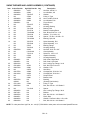
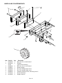
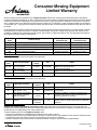


![スタートガイド[第4版]](http://vs1.manualzilla.com/store/data/006620278_2-f1f0d6169303d43042161b892c04144d-150x150.png)