1
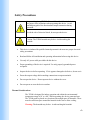
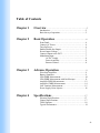
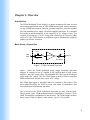
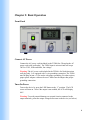
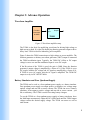
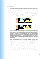
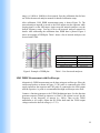
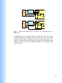
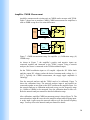
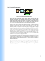
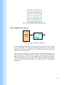
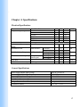
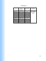
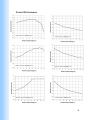
Accel Instruments User’s Manual TS200 Modulated Power Supply Battery Simulator/Emulation Waveform Amplifier Power/Current Amplifier PSRR/CMRR Measurement Voltage Supply Transient Measurement 1 Warranty Information Accel Instruments, LLC (hereon referred to as Accel Instruments) warrants this product for a period of one (1) year from date of shipment. If the device is defective within the warranty period, Accel Instrument will either repair or replace the product. Warranty is voided if the device is opened by anyone other than Accel Instruments. Warranty Limitations This warranty does not apply to normal wearing or misuse of the product or part. Failure to follow proper operating instructions described in this document is not cover by warranty. Warranty is void if any modification to the product without Accel Instrument’s express written consent. II2 Safety Precautions Output voltage is up 72VDC. To avoid the risk of electrical shock, use proper safety techniques when operating this device. Avoid touching any part of the non-insulated output connection during operation. Avoid the risk of electrical shock, do not open the device. Caution: The TS200 heatsink may be hot. Avoid touching the heatsink. This device is indented for qualified trained personnel who must use proper electrical safety precautions Read and follow all installation and operating information before using this device. Use only AC power cable provided with this device. Proper grounding of the device is required. Use only properly-grounded power receptacle. Inspect the device before operating. If it is appears damaged or defective, do not use it. Preset the output voltage before making connections to output terminals. Do not open the device. Do not operate device without the cover. Do not operate or store the device outdoor. Thermal Considerations The TS200 is designed for indoor operation and within the environmental temperature range of 0C to +40C. While operating, the device generates heat. The TS200 must be placed on a location with enough space all around it. There must be sufficient space around the heatsink in the rear to allow cooling. Warning: The heatsink may be hot. Avoid touching the heatsink. III 3 Table of Contents Chapter 1 Overview……………………….…………………………….5 Introduction………………………………………..……....5 Basic theory of operation……………....……………….....5 Chapter 2 Basic Operation……………………………….…………6 Front Panel…………………………….………..…………6 Connect AC Power………………….…………..…………6 Turn On Power………………………………….…………6 Enable/Disable the Output………………..…….…………7 Preset Output Voltage…………………………..…………7 Connect Output to the DUT…………………….……....…7 Modulation Input…………………….……………….....…7 AC/DC Couple…………………….……....………8 Power Amplifier…………………….……....……..8 Remote Control…………………….……...………8 Chapter 3 Advance Operation…………………….…………...…9 Waveform Amplifier…………………….………….......…9 Battery Simulator…………………….……………........…9 LDO PSRR Measurement…………………….…..…....…10 LDO PSRR Measurement with Oscilloscope………….…11 Amplifier PSRR Measurement…………………….......…12 Amplifier CMRR Measurement…………………….....…14 Line Transient Measurement…………………….….....…15 Power Supply Noise Injector……………………..…....…16 Chapter 4 Specifications…………………….…………………....…17 Electrical Specifications…………………….….……...…17 General Specifications…………………….…………...…17 TS200 Options…………………………….…………...…18 Typical Performance...…………………….…………...…19 IV 4 Chapter 1: Overview Introduction The TS200 Modulated Power Supply is a unique instrument for many test and measurement applications such as LDO PSRR measurement, battery simulator, op amp CMRR measurement, function generator amplifier, transient response test, four-quadrant power supply, lab power amplifier and more. It is designed for bench test and measurement. It can output DC or AC voltage or both. For example, it can output a 3.3V DC voltage with a 300mVpp AC sinewave riding on top of it. The TS200 features a modulation input to modulate the output to produce any desired waveform. Basic theory of operation AC Mod Input Output 0dB/20dB DC DC Offset Figure 1. TS200 Functional Equivalent Figure 1 shows the TS200 modulated power supply functional equivalent diagram. It consisted of an AC-coupled or DC-coupled input, a high current amplifier, and a DC output offset. The adjustable DC offset sets the modulated power supply DC voltage. This DC offset feature is ideal for LDO or amplifier PSRR measurement, because they require a DC voltage. The TS200 input signal is selectable either AC-coupled or DC-coupled. This allows added flexibility for TS200 to work with variety of instruments such network analyzers and function generators. The A-version of the TS200 modulation input gain by unity (non-inverted). The B-version of the TS200 modulation input is amplified by a factor of 10 or 20dB. The amplifier configuration is non-inverted. The TS200 output can drive heavy resistive load or capacitive load or both. Up to 3.5A is possible. 5 Chapter 2: Basic Operation Front Panel Connect AC Power Connect the AC power cord (included) to the TS200 first. Then plug the AC power cord to the wall outlet. The TS200 input is universal and can accept 100V to 230V, 50Hz and 60Hz, line voltage. Warning: The AC power cord included in the TS200 is for North American wall plug only. It is equipped with 3-wire grounding connection. The TS200 must be plug-in into a 3-wire outlet with proper grounding. For other regions, proper power adopter with must be used. Make sure the adopter has proper grounding connection. Turn On Power Turn on the device by press the LINE button to the “1” position. The LCD screen will turn on. Note if the output is not enabled, the LCD will display 0.0V. Warning: To avoid potential damages to external circuits connected to the output terminals, preset the output voltage before turn on the device (see below). 6 Enable/Disable the Output Press the ON/OFF button to enable the output. The ON/OFF button will lite with a green light. Press the ON/OFF button again will disable the output. The output is high-Z when disabled. Warning: To avoid the risk of electrical shock, always disable the output before making wire connections. While the output is enabled, avoid physical contact with any non-insulated electrical connections. Preset Output Voltage Before making any output wire connection, press the ON/OFF button to enables the output (previous section). The LCD displays the output voltage. Turn the OFFSET knob to set the DC voltage. Turn to the right to increase the voltage and turn to the left to decrease the voltage. Once the desired voltage is set, press the ON/OFF button to disable the output for output wire connection. Connect Output to the DUT The TS200 output terminals are designed for banana connectors. Connect the OUTPUT to the DUT (device under test) using cables with banana connectors (not included). For best performance, especially for high frequency applications, keep the connection wires as short as possible. Twist the + and – wires leads together to minimize inductance. For high current applications, make sure the connection wires are heavy gauge to avoid excessive voltage drop. Note: The TS200 output is isolated from the chassis. Modulation Input The TS200 features a modulation input (BNC connector). The modulation input modulates the TS200 output voltage. This feature makes the TS200 ideal for PSRR and CMRR measurement or as a current or power amplifier. Any voltage applied to MODULATION input will increase the output voltage. For example, while the TS200 is set to DC-couple, a +1V applied to MODULATION input will increase the TS200 output voltage by +1V for unity gain version or +10V for 20dB gain version. Warning: The MODULATION input maximum voltage is +/-20V. Exceed +/20V could damage the device. 7 AC/DC Couple The modulation input can be AC or DC coupled. Remember the output voltage is the superimposed of OFFSET voltage and MODULATION voltage. Power Amplifier The TS200 can be used as a current or power amplifier. The modulation input serves as amplifier input. The TS200 offers 0dB and 20dB gain options. Remote Control The MODULATION input can serve as a remote voltage setting. To do so, adjust the OFFSET knob until the voltage reaches 0.0V and set to DC-couple, then apply a DC voltage to MODULATION input. The DC input voltage can come from a programmable power supply or DAQ (data acquisition). Whatever the voltage on the MODULATION input is amplified and output to the OUTPUT terminals. Note the TS200 offers two gain options: 0dB and 20dB. 8 Chapter 3: Advance Operation Waveform Amplifier Function Generator Or AWG Mod Input Output TS200 Figure 2. Waveform amplifier setup The TS200 is also ideal for amplifying waveforms for driving high-voltage or high current or both. It is ideal for amplifying function generator output to drive heavy load. TS200 is ideal for laboratory power amplifier. Figure 2 shows the TS200 connection as a high voltage or power amplifier. The function generator or arbitrary waveform generator (AWG) output is connected the TS200 modulation input. Typically, the TS200 DC Offset or DC output voltage is set to zero and the modulation input is set to DC-couple. If the B-version of the TS200 is used, the gain is 20dB. Since the function generator’s output voltage is amplified by a factor of 10. If the TS200 is set to DC-couple, both the DC voltage and AC signal are amplified by a factor of 10. If TS200 is set to AC-couple, only the AC signal is amplified. The TS200 DC output is set by its DC OFFSET knob. Battery Simulator and Four Quadrant Supply The TS200 can be used as a four-quadrant power supply or a batter simulator. Four-quadrant power supply can output positive or negative (see voltage range option) voltage and can sink or source current. The TS200 can act as a battery simulator. It can output a positive voltage and can sink or source current – just like a real battery. The TS200 is useful for testing battery chargers. To use the TS200 as a four-quadrant power supply or battery simulator, leave the Mod Input unconnected. Adjust the DC Offset knob until the TS200 output voltage reaches the desired supply voltage. The TS200 can source as well as sink current. 9 LDO PSRR Measurement Power supply rejection ratio (PSRR) or some time called power supply ripple rejection measurement are often difficult to measure, especially when the device under test (DUT) is heavily loaded. Because most network analyzer cannot drive a heavy load, the TS200 modulated power supply is very useful for PSRR measurement for such devices as LDOs (low dropout regulators) and power amplifiers. PSRR measurement is easy with the aid of the TS200. Figure 3 shows how to measure PSRR. PSRR measurement technique involves a network analyzer, TS200 power amplifier, and device under test (DUT). Source Network Ananyzer Mod Input LDO Output TS200 DUT A Load B (a) Source Network Ananyzer Mod Input LDO Output TS200 DUT A Load B (b) Figure 3. LDO PSRR measurement setup. (a) Calibration setup, (b) PSRR setup. Figure 3 shows the LDO PSRR measurement setup. Using a network analyzer, the source is connected to the TS200 modulation input. The TS200 output is connected to the LDO supply input. It is recommended to reduce the LDO input capacitance to minimum. Since the TS200 can drive a heavy load, thus the LDO output can be loaded with the desired loading resistor (i.e. maximum specified load). Set the TS200 modulation input to AC-coupled. Adjust the DC Offset knob until the output DC voltage reaches the desired voltage (i.e. 3.3V). Typically for PSRR measurement, the supply ripple amplitude is 200mVpp. If you are using the A-version, set the network analyzer output to 200mV. If you are using the B-version and consider the modulation gain is 20dB, set the network analyzer output amplitude to 20mVpp. First the network analyzer and the TS200 need to be calibrated. Figure 3a shows the calibration setup. The network analyzer input-A and input-B are connected together at one point on the DUT board near the LDO supply input. Set the network analyzer to calibration mode and sweep over the frequency 10 range (i.e. 100Hz to 100kHz) to be measured. Save the calibration data for later use. Refer the network analyzer manual for detailed calibration setup. PSRR (dB) After calibration, LDO PSRR measurement setup is shown Figure 3b. The network analyzer input-B is moved to the LDO output near the capacitor while keeping input-A at the LDO input. Again sweep the network analyzer over the desired frequency range. You may refer to the network analyzer manual for details. After subtracting the calibration data, PSRR data is plotted. Figure 4 shows an example of PSRR plot. Table 1 shows a list of network analyzers can be used with TS200. Manufacturer AP Instruments Omicron Agilent Audio Precision Model Model 300 Bode 100 4395A SYS2722 Frequency (Hz) Figure 4. Example of PSRR plot. Table 1. List of network analyzers LDO PSRR Measurement with Oscilloscope Alternatively, PSRR measurement can be done using an oscilloscope. Place the oscilloscope probes as shown in Figure 5. CH1 probe is connected to the LDO supply input near the capacitor and CH2 probe is connected to the LDO output near the capacitor. 1x probe is recommended due high oscilloscope noise floor. Connect a function generator to the TS200 Modulation input. Set the function generator output to 200mVpp sinewave or 20mV if B-version is used. Set the frequency to the frequency of interest (i.e. 1kHz). Then set the TS200 modulation to AC-couple. Adjust the DC Offset knob until the TS200 output voltage reaches the desired voltage (i.e. 3.3V). 11 Function Generator Or AWG Mod Input Output LDO Load TS200 DUT CH1 Oscilloscope CH2 Figure 5. PSRR measurement using an oscilloscope. Using the oscilloscope, one can measure the amplitude voltage at CH1 and CH2. Divide CH2 by CH1 is the PSRR. One can use the below equation for PSRR calculation in dB. PSRR = 20log(CH2/CH1) If PSRR is better than 40dB, it is recommended to increase the TS200 output ripple voltage to 500mVpp due to oscilloscope has lower sensitivity than network analyzer. Amplifier PSRR Measurement The TS200 is also ideal for amplifier power supply rejection ratio measurements, especially power amps operating at maximum load conditions. Such amplifiers as audio amplifiers (class-A, B, AB, D and G) with heavy loading are ideal for TS200. The TS200 can also measure PSRR for op-amps, differential amplifiers, unity gain buffers, digital-to-analog converters, and analog-to-digital converters, etc. Op amp PSRR measurement is same as LDO except for a few minor differences. Please see Figure 6 and refer to the previous section, “LDO PSRR Measurement”, for amplifier PSRR measurement. 12 Source Network Ananyzer Mod Input Output DUT TS200 A Load B (a) Source Network Ananyzer Mod Input Output DUT TS200 Load A B (b) Figure 6. PSRR measurement setup for amplifier. (a) Calibration setup, (b) PSRR setup. As shown in Figure 6, the amplifier input is grounded, either AC or DC ground, for PSRR measurement. Calibrate the setup as shown in Figure 6a with the network analyzer input-A and input-B connected to the same point at the amplifier’s supply input. After calibration, move input-B to the amplifier output as shown in Figure 6b. Then measure PSRR in the same way as the LDO in the previous section. 13 Amplifier CMRR Measurement Amplifier common-mode rejection ratio or CMRR can be measure with TS200. Figure 7 shows how to measure CMRR. CMRR measurement for amplifiers is same as PSRR except for a few minor differences. DUT Source Network Ananyzer Mod Input Output Load TS200 A B (a) DUT Source Network Ananyzer Mod Input Output Load TS200 A B (b) Figure 7. CMRR measurement setup for amplifier. (a) Calibration setup, (b) CMRR setup. As shown in Figure 7, the amplifier’s positive and negative inputs are connected together and connected to the TS200’s output. Using a network analyzer, the source is connected to the TS200 modulation input. Set the TS200 modulation input to AC-coupled. Adjust the DC Offset knob until the output DC voltage reaches the desired common-mode voltage (i.e. ½ VCC). Typically for CMRR measurement, the supply ripple amplitude is 200mVpp. First the network analyzer and the TS200 need to be calibrated. Figure 7a shows the calibration setup. The network analyzer input-A and input-B are connected together at one point on the DUT board near the amplifier input. Set the network analyzer to calibration mode and sweep over the frequency range (i.e. 100Hz to 100kHz) to be measured. Save the calibration data for later use. Refer the network analyzer manual for detailed calibration setup. After calibration, amplifier CMRR measurement setup is shown Figure 7b. The network analyzer input-B is moved to the amplifier output while keeping inputA at the input. Again sweep the network analyzer over the desired frequency range. You may refer to the network analyzer manual for details. 14 Line Transient Measurement Function Generator Or AWG Mod Input Output LDO/SMPS Load TS200 DUT CH1 Oscilloscope CH2 Figure 8. Line transient measurement setup. Most LDOs and switch-mode power supply (MSPS) specified their line transient specifications. Line transient response specifies its output voltage change after an input voltage step change. For example, an LDO specified its output voltage deviates less than 5mV for a 200mV input voltage step from 3.6V to 3.8V in 10 microseconds. This is also called line step response. Figure 8 shows how to measure line transient response. A function generator generates a square pulse with a specific rise and fall time (i.e. 10us). The function generator is connected to the Mod input of TS200 and the TS200 output is connected to the device under test. Typically the TS200 is set to DCcouple. Set the function generator’s pulse high and low voltages generate the transient step. For example, to generate a 3.6V to 3.8V voltage step, set the function generator output voltage low to 3.6V and output high voltage to 3.8V. If B-version is used, set the output voltage low to 0.36V and output high voltage to 0.38V, since the TS200 gain is 20dB. It is recommended to keep the DUT input capacitor to minimum (0.1uF or less) to allow faster rise and fall time. Use as short cables as possible (Less than 12 inches) connecting TS200 output and the DUT. Twist the cables to together to minimize inductance. To measure the line transient step, connect an oscilloscope probe (CH1) to the DUT input and another probe (CH2) to the DUT output as shown in Figure 8. The transient response is measured at CH2. Figure 9 shows an example of line transient measurement. 15 Figure 9. Line transient measurement example. Power Supply Noise Injector Function Generator Or AWG Mod Input Output TS200 Figure 10. Power supply noise simulator In some applications, the device under test may be sensitive to power supply noise. For example, VCO (voltage controlled oscillator) phase noise may be degraded with excessive supply noise. The TS200 can be used to aid supply noise sensitive circuit testing. Figure 10 shows a supply noise simulation setup. The function generator is set to noise output. The function generator output is connected to the TS200 Mod input. The input is set to AC-couple. Adjust the DC Offset knob until the TS200 output voltage reaches the desired DUT supply voltage level. Adjust the noise level on the function generator to see how the DUT is responded to supply noise. 16 ` Chapter 4: Specifications Electrical Specifications Parameter Output Voltage Range Continues Output Current Modulation Input Voltage Range Modulation Gain Min Modulation Frequency Max Modulation Frequency Slew Rate LCD Voltmeter Accuracy Condition/Note TS200-0 TS200-1 TS200-2 TS200-3 TS200-4 TS200-5 See Typical Performance Curves DC Non-inverted -3dB, no load -3dB, no load, small signal Midrange A-version B-version AC-Coupled DC-Coupled AC-Coupled DC-Coupled MIN TYP MAX -10 +10 -20 +20 -20 +45 -10 +70 0 +15 -40 +40 -20 +20 0 20 UNIT V V dB 1 Hz DC 1.0 1.0 16 ±1.0 MHz V/s % General Specifications Power supply adapter Input Voltage Power supply adapter Input Frequency Operating Temperature Range Storage Temperature Range Operating Humidity Range Weight Dimension (Inches) 100VAC to 240VAC 50Hz/60Hz 0°C to 40°C -20°C to +60°C 20% to 80% (no condensation) 3.6 kg 10.0” x 8.5” x 5.25” 17 TS200 Options Options TS200-0A TS200-0B TS200-1A TS200-1B TS200-2A TS200-2A TS200-3A TS200-3B TS200-4A TS200-5A TS200-5B Output Voltage Range -10V to +10V -10V to +10V -20V to +20V -20V to +20V -20V to +45V -20V to +45V -10V to +70V -10V to +70V 0V to +15V -40V to +40V -40V to +40V Modulation Gain (V/V) Output Current +1 +10 +1 +10 +1 +10 +1 +10 +1 +1 +10 See Typical Performance Curves 18 Typical Performance 19 Typical Performance 20 Accel Instrumentsl Email: [email protected] Website: www.accelinstruments.com 21