1
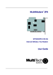
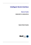
MultiModem® ZPX
V.92 Internal Modem
MT9234ZPX-UPCI
MT9234ZPX-UPCI-NV
MT9234ZPX-PCIe
MT9234ZPX-PCIe-NV
Quick Start Guide
MultiModem ZPX Quick Start Guide
MT9234ZPX-UPCI, MT9234ZPX-UPCI-NV
MT9234ZPX-PCIe, MT9234ZPX-PCIe-NV
82100132L Rev. C
Copyright
This publication may not be reproduced, in whole or in part, without prior expressed
written permission from Multi-Tech Systems, Inc. All rights reserved.
Copyright © 2010 Multi-Tech Systems, Inc.
Multi-Tech Systems, Inc. makes no representations or warranty with respect to the
contents hereof and specifically disclaims any implied warranty of merchantability or
fitness for any particular purpose. Furthermore, Multi-Tech Systems, Inc. reserves
the right to revise this publication and to make changes from time to time in the
content hereof without obligation of Multi-Tech Systems, Inc. to notify any person or
organization of such revisions or changes. Check Multi-Tech’s Web site for current
versions of our product documentation.
Revision Date
Description
A
12/28/07
Initial release
B
10/29/09
Added 64-bit drivers, Windows 7 support, and Support
Portal link.
C
04/13/10
Windows Installer instructions replace old installation.
Trademarks
Multi-Tech, MultiModem, and the Multi-Tech logo are registered trademarks of
Multi-Tech Systems, Inc. Windows 2003, XP, Vista, Windows 7, and Windows
Server 2008 are registered trademarks of Microsoft in the U.S. and other countries.
World Headquarters
Multi-Tech Systems, Inc.
2205 Woodale Drive, Mounds View, Minnesota 55112
Phone: 763-785-3500 or 800-328-9717 Fax: 763-785-9874
www.multitech.com
Contacting Multi-Tech Support
Online Support Portal:
https://support.multitech.com
In order to better serve our customers, manage support requests and shorten
resolution times, we have created the online web portal allowing you to submit
questions regarding Multi-Tech products directly to our technical support team.
Knowledge Base and Support Services:
www.multitech.com/support.go
The Knowledge Base provides immediate answers to your questions and gives you
access to support resolutions for all Multi-Tech products. Visit our support area on
the website for other support services.
Country
Europe, Middle East, Africa:
U.S., Canada, all others:
By Email
[email protected]
[email protected]
Warranty
Warranty information can be found at:
2
By Phone
(44) 118 959 7774
(800) 972-2439
or (763) 717-5863
http://www.multitech.com/warranty.go
Multi-Tech Systems, Inc.
Introduction
This guide shows you how to set up your MultiModem ZPX. For detailed
information, product specifications, troubleshooting tips, and more, see the User
Guide, available on your MultiModem CD.
Check Multi-Tech’s Web site for current versions of our product documentation.
Safety Warnings
● Use this product only with UL- and CUL-listed computers.
● To reduce the risk of fire, use only UL-listed 26 AWG (.41 mm) or larger
telephone wiring.
● Never install telephone wiring during a lightning storm.
● Never install a telephone jack in a wet location unless the jack is specifically
designed for wet locations.
● Never touch uninsulated telephone wires or terminals unless the telephone
line has been disconnected at the network interface.
● Use caution when installing or modifying telephone lines.
● Avoid using a telephone during an electrical storm; there is a risk of electrical
shock from lightning.
● Do not use a telephone in the vicinity of a gas leak.
● The telephone cord is to be disconnected before accessing the inside of the
equipment.
Windows Installer
Your product CD contains an installer program for current Windows operating
systems (Windows XP and newer only) that should be used before installing your
ZPX card. Should you happen to install your ZPX card before using the installer
program, please follow the directions in the User Guide on the product CD for your
particular version of Windows.
1.
Insert the product CD into a compatible drive. Do not install your ZPX
card yet.
2.
Click on the Preinstall Windows Drivers button from the main splash
screen of the CD.
Multi-tech Systems, Inc.
3
4
3.
Click the button that matches your operating system [32-bit or 64-bit].
You can see what type of system you are using from the Control Panel |
System screen.
a. Windows may pop-up a User Account Control window. Select
the YES button to continue with the driver installation.
4.
Click on the next button to start the driver pre-installation.
5.
You will be prompted to confirm the installation of the necessary drivers.
Click the Install button to continue each time.
6.
There will be a transitory screen, then the process will complete. Click on
the Finish button.
7.
Your driver installation is complete. You can now physically install your
ZPX card using the next set of instructions.
Multi-Tech Systems, Inc.
Installing your MultiModem
Before inserting your ZPX into a PCI slot, please run the Windows Installer program
from your product CD. This makes all Windows operating systems installations
faster than the manual methods described in the User Guide.
1. Turn off your system and unplug it. Failure to do so may result in damage to
both the MultiModem and your system. Do not turn on the system until the
instructions tell you to do so.
2.
Remove the cover from your system as instructed in the system manual.
Before handling the ISI Card, discharge any static in your body by touching
a piece of grounded metal such as the computer chassis. Electrostatic
discharge (ESD) is the release of stored static electricity that can damage
electrical circuitry or components. Static electricity is often stored in your
body, and discharged when you come in contact with an object of a different
potential.
Perform the procedure below described in this section only at an ESD
workstation using an antistatic wrist strap. If such a station is not available,
you can provide some ESD protection by wearing an antistatic wrist strap
and attaching it to a metal ground screw (lug).
3. If you are installing a MT9234ZPX-PCIe board in a low profile machine, you
will have to change the mounting bracket to the low profile mounting bracket.
Refer to your User Guide for low profile mounting bracket details.
4. Select an empty PCI expansion slot. Remove the expansion slot cover and
save the retaining screw.
5. Before handling the MultiModem, discharge static in your body by touching a
bare piece of metal on the chassis. Carefully remove the MultiModem from its
antistatic bag, handling it only by the mounting bracket and edges. Do not
touch the gold-plated connectors along the bottom edge.
6. Look at the system’s main board to determine either PCI or Express
connector. Place the MultiModem directly above the expansion slot and
gently, but firmly, push it into the connector until the card’s retaining bracket
is flush against the system chassis.
7. Fasten the retaining bracket to the system chassis with the screw saved in
step 4.
8. Replace the system cover.
Multi-tech Systems, Inc.
5
Making External Connections
Now, connect the MultiModem to the telephone line and, optionally, to your
telephone. For voice mail or speakerphone, you can also connect it to a
microphone and an external speaker, headphone, or sound card. The microphone
can be used for recording answering machine messages or for speakerphone use.
The speaker or headphone can be used for playing back messages or as a
speakerphone.
PHONE
PH ONE
LINE
L INE
MIC IN
Optional Voice
MIC
LINE OUT
L INE
Line Connection
Plug one end of the provided telephone cable into the modem’s LINE jack, and the
other end into a telephone wall jack. This is the only required connection.
Important: The LINE jack is not interchangeable with the PHONE jack. Do not plug
the phone into the LINE jack or the line cable into the PHONE jack.
Note: The Federal Communications Commission (FCC) and Industry Canada
impose certain restrictions on equipment connected to public telephone systems.
Configure the Modem for Your Country
Different countries have different requirements for how modems must function.
Therefore, before you use your modem, you must configure it to match the defaults
of the country in which you are using it. The modem is set to country, Euro/NAM,
with a country code of 52 decimal by default. You can use one of two configuration
methods:
● Using the Global Wizard to Configure Your Modem
● Using AT Commands to Configure Your Modem
6
Multi-Tech Systems, Inc.
Using Global Wizard to Configure Your Modem
The Global Wizard configuration utility is recommended for computers running
Windows 2000 or newer.
1.
2.
3.
Insert the MultiModem system CD into the CD-ROM drive.
When the splash screen appears, click Initial Setup & Country Sel button.
Choose either:
a. Run Global Wizard from CD. This will not load the wizard onto your
hard drive, or
b. Install Global Wizard on the HD. This will install the wizard onto your
hard drive for future use.
4. The Global Wizard dialog box appears. Click Next.
5. The Wizard searches for your modem and identifies it. Click Next.
6. Select the country in which the modem will be used. Click Next.
7. Review your choice of country. If it is correct, click Next to configure the
modem.
When Global Wizard announces that the parameters have been set, click Finish to
exit.
Using AT Commands to Configure Your Modem
Non-Windows users can configure the modem using AT commands. You must
enter these commands in your communication program terminal window.
1. Run your favorite communication program and open the program terminal
window.
2. To configure the modem for a specific country:
Type AT%T19,0,nn (where nn is the country code in hexadecimal format
Press ENTER.
The message OK displays.
3. To verify the change:
Type ATI9.
Press ENTER.
The country code is displayed in decimal format, as in this example:
Country
Euro/NAM
AT command
(hexadecimal)
AT%T19,0,34 (default)
Country code
(decimal)
52
The complete list of country codes can be found on the Multi-Tech Web site at:
http://www.multitech.com/en_US/PRODUCTS/Categories/Device_Networking/
global_modems/configuration.asp
Multi-tech Systems, Inc.
7
8
82100132L