1
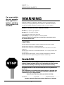
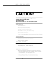
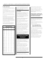
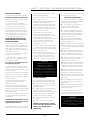
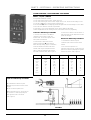
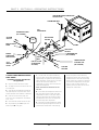
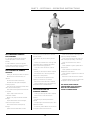
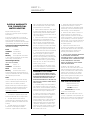
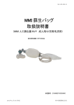
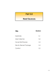
Raypak Commercial
Water Heaters
Part 1: Safety warning
Part 2: Models 507 NCO, 538 to 4224 NCO, NCM
Part 3: Warranty
CONTENTS
Part 1: For Your Safety
Part 2: Models 507 NCO, 538
to 4224 NCO, NCM.
Section 1. Installation Instructions
Section 2. Owners Operating
Instructions
Part 3: Warranty
Date of Installation:
//
//
Model No.
Serial No.
Installed by:
Purchased from:
This Installation and Operating Instructions Manual is
provided with the necessary information for the proper
installation, operation and maintenance of your Raypak
Heater. Please review and follow these procedures
carefully. Keep this manual in a safe and accessible place
for easy reference in the future.
3
PART 1 FOR YOUR SAFETY
For your safety
do not operate
this appliance
before reading
this instruction
booklet.
WARNING
Improper installation, adjustment, alteration, service or maintenance can
cause injury or property damage. For assistance or additional information
consult your Raypak distributor, qualified installer, or service agency.
WHAT TO DO IF YOU SMELL GAS?
DO NOT try to light any gas appliance
DO NOT touch any electrical switch.
Turn off the gas supply at the gas meter
Immediately, call your gas supplier or licensed gasfitter.
NOTE: Some gases are heavier than air and it may be necessary to check
for gas leaks at floor level.
CAUTION
DO NOT Operate this appliance before reading this instruction booklet.
DO NOT Place articles on or against appliance.
DO NOT Store chemicals or flammable materials in the same room as this
appliance.
DO NOT Store chemicals or flammable materials, on, or spray aerosols near
this appliance.
DO NOT Operate with panels, covers or guards removed from appliance.
DO NOT Enclose this appliance (applies to external models only).
DANGER
Water temperatures above 45 Degrees Celsius can cause severe burns.
Children, disabled and elderly persons are at the highest risk of being scalded.
Feel water before bathing or showering and supervise where necessary.
Keep this manual in a safe and accessible place for easy reference in
the future.
This Installation and Operating Instructions Manual is provided with
the necessary information for the proper installation, operation and
maintenance of your Raypak Heater.
Please review and follow these procedures carefully.
Model No. ..................... Serial No. .................... Installation Date ..................
Part No. 209130.5: Effective 08/01/2001 (Replaces: 01/10/2000)
4
PART 1 - FOR YOUR SAFETY
CAUTION!
Ceramic Firetile Refractory is used in Raypak Heaters
Possible risks of irreversible effects
Harmful by inhalation
May be irritating to the skin, eyes and respiratory system.
WHEN HANDLING
• Minimise airborne dust.
• Wear an approved mask or respirator.
• Avoid any contact with the skin and eyes.
• Wear suitable loose-fitting, long-sleeved clothing.
• Wear gloves and eye protection.
• Consult Occupational Health and Safety Authority for any further information.
AFTER HANDLING
• Rinse any exposed skin areas with clean water.
• Wash work clothing separately.
FIRST FIRING OF HEATER
• Fumes and smoke may be produced.
• Avoid breathing fumes, ventilate area to clear.
• Production of smoke should cease within 30 minutes
REMOVAL OF USED PRODUCT
• Wear an approved mask. Over-exposure to dust formed after service
may cause respiratory disease since cristobalite, a form of crystalline
silica may be formed above 900 degrees Celsius.
• Consult Occupational Health and Safety Authority for further
information regarding removal of used ceramic fibre linings.
5
Raypak Commercial
Water Heaters
Part 2: Models 507 NCO, 538
to 4224 NCO, NCM.
6
SECTION I INSTALLATION INSTRUCTIONS
Before you commence the installation:
5601/AG601 and electrical codes and/or
statutory body codes and regulations.
trees, fences, or other equipment, etc must not
obstruct the front of the heater.
2.
Check that the heater you have
been supplied is suitable for the type of
installation and the gas that is available.
The gas supply pressure must be between
the minimum and maximum as shown on
the heater data plate.
INSTALLATION
PROCEDURES INSPECTION OF
EQUIPMENT
COMBUSTION / VENTILATION
AIR
These instructions are provided to ensure the
correct installation and operation of your
Raypak Hot Water Heater. Whilst all care has
been taken to provide the correct information
we also rely on your expertise and quality
workmanship to provide the end user with a
high class installation.
Check the heater and associated equipment for
any damage and notify your local representative
or Raypak for any further instructions.
1.
Read these instructions in full!
Should any questions arise regarding the
specifications, installation, operation or
servicing of this heater, we suggest that your
local representative or Raypak Customer
Service be consulted.
Raypak heaters utilise a finned copper tube
heat exchanger resulting in a low water
content and reduced "stand by" heat losses.
Therefore a circulator pump of sufficient
capacity to match the heater model must be
installed in the system.
Raypak heaters are fitted with Australian Gas
Association approved components and all
heaters in this range are designed to comply with
AS 3814/AG501.
Some models are designed for either indoor or
outdoor installation subject to the appropriate
indoor draft hood or outdoor stackless top
being fitted. It is the responsibility of the
installer to locate the heater in such a manner
that correct operation is obtained.
Check that the correct top for your installation
has been supplied.
RAYPAK will not be held responsible for any
damages which are caused to the appliance
due to its location and caused by means
beyond the control of Raypak, EG High Winds,
Downdraft, Incorrect installation etc.
WARNING:
This appliance must be installed to AS 3500.4
and may require a Backflow Prevention Device
as part of the installation.
All electrical, gas piping, gas connection and
flueing of the heater must only be undertaken
by a properly authorised person. The
installation must comply with local gas, AS
DO NOT INSTALL OR START UP ANY RAYPAK
SUPPLIED PRODUCT THAT HAS BEEN
DAMAGED, WITHOUT FIRST CONSULTING
RAYPAK AS ANY DAMAGE OR FAULTS CAUSED
BY UNAUTHORISED START UP MAY NOT BE
COVERED BY OUR WARRANTY.
HEATER LOCATION AND
CLEARANCES
The heater and any Raypak supplied equipment
should be located so that any possible water
leaks will not cause damage to any adjacent
areas or structures. When such locations
cannot be avoided, it is recommended that a
suitable drain pan, adequately drained, be
installed under the heater.
This pan should be large enough for all of the
equipment and must not restrict combustion
airflow. Any damage caused by water leaks is
the responsibility of the installer.
The heater must be mounted on a level noncombustible base such as a concrete slab,
concrete plinth, steel plate etc. Raypak
heaters and equipment must not be installed
on carpeting.
Any gas or water piping, electrical conduits,
HEATER CLEARANCES
Clearance from non-combustible materials:
Models 507 to 1922
Rear
150mm
Left Side
300mm
Front
750mm
Right Side
300mm
Ceiling
1200mm
Clearance from combustible materials:
Rear
600mm
Left Side
600mm
Front
750mm
Right Side
600mm
Ceiling
1200mm
7
Indoor model heaters must only be installed in
a protective enclosure or properly constructed
plant room with adequate ventilation in
accordance with AS 5601/AG 601 Gas
Installation Code.
Ventilation shall be via 2 permanent openings
directly to outside, one at an upper level and
one at low level.
The minimum free area provided by each vent
shall be as calculated by using the following
formula, unless otherwise stated in AG 601.
A =1.5 X T
Where A = Minimum free ventilation area (cm2)
T = Total hourly input of all appliances (Mj/h)
Note: The minimum dimension of any opening
shall be 6mm.
Please take the heater location into account
when locating the fresh air vents because any
excessive draft will cause flame disturbance
and probable pilot outage. In some cases
where excessive draft effects the burner, the
risk of major damage is high due to
incomplete combustion.
Installations, which obtain air from a source
other than directly from outside, must comply
with AS 5601/AG601.
Warning: Air supply to the heater room must not
be affected by mechanical exhaust vents located
in other parts of the house or building, such as
kitchen or bathroom fans, spa blowers, etc.
Mechanical exhaust vents may create a negative
Models 2004 to 4224
350mm
600mm
1200mm
600mm
1200mm
600mm
600mm
1200mm
600mm
1200mm
PART 2 - SECTION I - INSTALLATION INSTRUCTIONS
pressure in the heater room that can become a
hazard by asphyxiation, explosion or fire.
Caution: Do not store chemicals or flammable
materials in the same room or near this heater.
Do not use aerosols near this heater whilst it is
in operation.
FLUEING
The correct Draft hood must be fixed to the top
of the heater and connected to a properly
constructed flue, vented to the outside using
only approved fittings.
Reduction of the flue diameter or alteration to
the draft hood voids all warranty.
Where flueing may be difficult, please contact
Raypak for advice, we will have solutions,
particularly where a fan assisted flue may be
the answer.
vertical flue of three (3) metres to ensure
correct draft. Consult Raypak for advice if
length is shorter.
OUTDOOR HEATERS
Must not be installed inside any roofed
structure or under eaves, roof overhangs, or
pool decks. It should also be at least 1500
mm, in any direction from any window or fresh
air opening.
• On large elevated
decks fill in to at
least one metre all
around unit
Gas
Connection
Elevated Deck
used, a suitable plate material must be used to
fill in the perforations. This is very important, as
any excessive drafts must not be able to enter
the unit from directly underneath.
HIGH WIND CONDITIONS
Minimum
flue length
3 metres
Self-supporting flue
Bolted sleeve
Correct draft converter
(Indoor hood)
610 mm
This area must be
filled in
Water
Connections
Where practicable the flue should run vertically.
Lateral (raised above horizontal) is acceptable
but the run of a flue shall not exceed 50% of
Distance above roof must be
as stated in AG601
HIGH WIND TOP
When installing the heater on a raised base,
please make sure that the base material is
solid and filled in. E.G. If steel mesh decking is
The weight of the flue must not rest on the
heater draft diverter, the flue must be selfsupporting and be fitted with a disconnection
section (bolted sleeve) to enable the heater
top and draft diverter to be removed easily,
for servicing.
AGA Approved Cowl
recommend that the common practice of
surrounding the plant and equipment within an
open top enclosure be adhered to. The installer
would meet the costs for this enclosure, heater
relocation and/or windbreak.
On some rare occasions or in areas where high
winds frequently occur, at ground level, it may
be necessary to locate the heater a minimum
of one (1) metre away from high vertical walls,
or to install a wind break so that the heater is
not in direct wind current.
High rise or multi storey installations can
present problems with excessive winds and we
Wind Deflection Plate
Prevailing
Winds
Heater
Should the installation of a windbreak still not
remedy "Down draft", on models 538 to 1852,
Raypak can supply a Wind Deflection Plate (at
extra cost), to eliminate constant ignition
failures or flame disturbance, the need for
which would be determined by an approved
Raypak Service Person.
In areas of "constant extreme winds" or where
a Wind Deflection Plate is not appropriate, it
may be necessary to replace the "standard"
low profile outdoor hood with a HIGH WIND
TOP (which would be at extra cost.) The HIGH
WIND TOP serves the same function as the
low profile outdoor hood and should be
installed in accordance with the same
clearance requirements.
There can be occasions where seasonal or
unexpected climatic conditions will cause
failures of the heaters to operate, Raypak
cannot be held responsible for any of these
types of faults that are beyond their control.
Why not consider installing a remote reset
button and fail indicator to eliminate
inconvenience for the end user in the instances
of unavoidable failures? See the electrical
section for more information.
GAS SUPPLY
total flue height and shall be designed to rise
not less than 20 mm per 1 m run. The flue
must be terminated with an approved cowl.
Raypak recommends a minimum length of
High Wind Windbreak
The gas supply pipe must be sized to give
sufficient pressure and volume for the correct
operation of the heater. The gas line must be
fitted with an isolation valve. Consult AS
5601/AG 601 for further details.
CAUTION:
The gas supply must be isolated from the heater during pressure testing of the gas fitting line. Dissipate test pressure and make sure that any internal debris is
removed from the pipe before reconnecting to the heater.
Failure to follow this procedure may result in damage to the gas valve. (Damaged valves etc are not covered by our warranty.)
The heater and its gas connection must be thoroughly leak tested before placing in operation. Use soapy water and a manometer for leak test.
DANGER! Do not use an open flame to check for gas escapes.
8
PART 2 - SECTION I - INSTALLATION INSTRUCTIONS
PUMP SELECTION
In order to obtain the best possible hydraulics
in your system, you must select the correct size
water-circulating pump.
It should normally be installed so as to pump
water into the heater and this is particularly
important where the system water pressure
is low.
Refer to Flow Rate and Pressure Drop chart
and allow for the system head pressure when
sizing the pump.
Where the water flow rate exceeds the maximum
shown in the chart, a by pass valve must be
installed to reduce the water flow through the
heater. If the water flow rates are below the
minimum shown, a supplementary pump may be
required. (Please consult your local representative
or Raypak for any assistance).
A pump run on timer is fitted to remove any
residual heat from the heater and prevent any
nuisance tripping of the high limit switch.
WATER FLOW RATE AND
PRESSURE DROP.
Model
507
538
658
768
868
972
992
1142
1182
1242
1292
1362
1412
1492
1552
1662
1722
1852
1922
2004
2214
2404
2634
2804
3164
3304
3694
3804
4224
10 Deg C Rise
20 Deg C Rise
l/sec
kPa
l/sec
kPa
2.5
2.9
3.5
4.1
4.6
5.2
5.4
6.1
6.3*
6.3*
6.3*
6.3*
6.3*
6.3*
6.3*
6.3*
6.3*
6.3*
6.3*
11.7
11.7
12.0*
12.0*
12.0*
12.0*
12.0*
12.0*
12.0*
12.0*
21
7
11
15
23
28
30
44
45
47
47
49
49
52
52
55
55
58
58
45
45
48
48
50
50
54
54
57
57
1.3
1.4
1.8
2.0
2.3
2.6
2.7
3.0
3.2
3.3
3.4
3.6
3.8
3.9
4.1
4.4
4.6
4.9
5.1
5.5
5.9
6.5
7.0
7.9
8.4
9.2
9.9
10.5
11.3
5
3
3
4
5
7
7
10
11
13
13
16
21
21
22
27
30
36
39
12
12
18
18
21
21
30
30
42
42
* Where marked as maximum water flow, the
temperature rise will be greater than 10 Deg. C.
If a system water temperature rise in excess of
20 Deg C is required, please contact Raypak
for advice. Systems with multiple zones may
require additional pump(s).
COLD WATER MAKEUP/SUPPLY.
Heating heaters: We recommend that a cold
water feed regulator (Pressure Reducing Valve)
be installed and set at 50 kPa minimum
pressure. Backflow prevention in accordance
with A.S. 3500 may be required, please check
with the local water supply authority for any
local code requirements etc.
Alternatively a cold feed (header) tank may be
used. The minimum recommended height
above the heater is five (5) metres.
A minimum system water pressure of 70 kPa
COLD is required. (Most systems operate at
100 kPa COLD.)
A suitably sized expansion vessel must be fitted
to a closed heating system to prevent any
unnecessary waste of water from the system and
discharge of any inhibitors that may be present.
IMPORTANT: When installing a new heater to
an old system, it is a Raypak requirement
that the system and its equipment be
inspected and if necessary, drained and
flushed out with clean fresh water, before the
new heater is connected.
Failure to do this may cause blockages and/or
heater damage which is NOT COVERED BY
WARRANTY and any damage caused would
result in extra costs to repair etc.
IF THERE ARE ANY DOUBTS
ABOUT THE SYSTEM, DRAIN
AND FLUSH AS A
PRECAUTION.
Domestic Hot Water heaters: These heaters are
normally connected to a storage tank and the
cold water supply must be fitted with a
Pressure Limiting Valve, if the water supply
pressure exceeds the pressure indicated on the
storage tank.
As with Heating systems, the heater will
operate at a minimum water pressure of 70
kPa (COLD) however, the design of any hot
water system must be such that the water
pressure is sufficient for the fixtures.
We recommend the installation of a cold water
expansion valve (in accordance with AS 3500)
to prevent unnecessary discharge of hot water
from the tank pressure and temperature relief
valve and subsequent waste of energy.
WATER QUALITY
The standard finned copper tube heat
exchanger has proved to be very resilient and
9
capable of operating for many trouble free
years on most reticulated water supplies.
Should your installation be in an area where
"corrosive" or "hard" water is present, it would
be advisable to contact Raypak before
installation to ensure that the quality of the
water is satisfactory.
DAMAGE CAUSED BY "CORROSIVE, HARD
OR OTHERWISE POOR QUALITY WATER", IS
NOT COVERED BY OUR WARRANTY.
PIPING.
Heating heaters: We recommend that all high
points of the system be vented or fitted with
automatic air vents.
The design of the system must be such that
the heater is provided with adequate water flow
and pressure at all times.
On radiator or heating systems where
ALL BY- PASS VALVES must be
installed at the end of the system.
thermostatic or zone valves will vary the water
flow, a suitable by-pass valve must be installed
to control heater water flow.
Domestic Hot Water heaters: If the heater is
supplied as part of a package, including the
tank and pump, the installation must comply
with the drawing provided. Failure to observe
this requirement may result in an ineffective
hot water capacity or damage.
For installation of the heater to an existing
storage vessel we suggest that advice be
sought to eliminate possible problems.
PART 2 - SECTION I - INSTALLATION INSTRUCTIONS
ELECTRICAL WIRING
The electrical power consumption of the heater is:
240 Volts AC, 50/60 Hz, of less than 1 Amp.
A normal 10 or 15 Amp, single phase power
circuit should be suitable.
Access to the electricals is achieved by
removing the cover of the control panel. (See
Location of Controls for different models.)
The heater must be properly earthed and
Raypak highly recommends the installation of
an RCD (Residual Current Device) for added
electrical safety. If the site is "electrically
noisy", a mains filter can be supplied at extra
cost, to eliminate Microzone failures.
THE HEATER MUST NOT BE ABLE TO
OPERATE WITHOUT THE CIRCULATING
WATER PUMP RUNNING.
The heater (240 Volts) power supply must be
"interlocked" via the auxiliary contacts of the
pump contactor (relay) etc or alternatively the
power supply for the pump and the heater
must operate off the same circuit and isolation
switch. (Parallel connection)
A Flow Switch is not regarded as an interlock
and must not be used as one.
If a Microzone control is fitted and the pump
control is used, this is recognised as being
interlocked with the heater.
Any other form of interlocking must
be approved by Raypak.
A pump run on timer is fitted so that at any
time that the heater is no longer required, the
heater shuts off and the pump continues for at
least ten (10) minutes.
If a Microzone is installed and the pump control
is used, this run on is included in the program.
A Raypak "Economaster" fitted as - standard
on all other heaters.
For servicing purposes we suggest that the
isolation switch be installed as near as
practical to the heater.
If there is any control wiring etc which is not
isolated by this switch then a suitable warning
label must be affixed to the heater which will also
direct the service person to the isolation switch
for that particular wiring.
E.G. More than one isolation switch is required to
turn off the power supply, Extra switch(es) on
switchboard etc.
CAUTION: Do not locate cables in front of
or underneath the burner, please consult
Raypak for advice if unsure.
Where cables or conduit, trunking etc are to be
mounted on the heater casing, please keep at
least 10mm air gap from the heater casing to
eliminate possible overheating.
Do not locate cables etc where they will restrict
access covers, doors etc.
Where the clearance from the right hand side
of the heater (models 538 to 1922) is
restrictive, please notify Raypak at the time of
manufacture and we may be able to relocate
the control panel for a minimal extra cost, if
this is not possible then a field retrofit may be
the best solution. (At extra cost)
If a Microzone or any other PLC device is
installed as part of the heater control etc,
please observe the requirements for suitably
screened data cable when utilising the
communication areas of these devices. Failure
to do so will result in malfunctions and /or
damage to the device, which will cause
inconvenience to the user.
Failure of, or damage caused to the Microzone
or any other heater component due to incorrect
wiring is NOT covered by our warranty and any
repairs will be at extra cost.
There are many variations to the types of
controls available and also RUN & FAIL indication
can be supplied. Advice on remote location of
reset button and failure indication is available
from your local representative or from Raypak.
WARNING:
COMMISSIONING MUST ONLY BE
UNDERTAKEN BY A PROPERLY
AUTHORISED AND IN SOME CASES
APPROPRIATELY LICENSED PERSON WHO
IS FAMILIAR WITH SAFE COMMISSIONING
PROCEDURES. THE COMMISSIONING MAY
REQUIRE INSPECTION BY THE GAS SUPPLY
AUTHORITY, CHECK IF THIS IS APPLICABLE.
COMMISSIONING
1. Check that all necessary approvals and
appropriate documents have been obtained.
2. Ensure that the heater is clean and the
surrounding area is clear of all combustible and
flammable materials.
3. Remove all liquids and chemicals from the
plant room and check that combustion air
openings are not obstructed. Chemicals must not
be stored in the plant room - this is extremely
dangerous and may damage the heater.
4. Fill the system with water and expel any
air as required.
5.
Purge all air from gas supply piping.
CAUTION: Liquid Propane Gas is heavier
than air and sinks to the ground, exercise
extreme care in lighting heater in
confined areas.
10
6. Test ALL gas connections for leaks, using
soapy water and a manometer.
( DO NOT USE A NAKED FLAME )
7. Conduct a visual inspection of the heater
and equipment for any damage or installation
problems and report as necessary.
8. Check that the correct power supply is
available and the circulation pump is
electrically interlocked with the heater.
9. Check that the ventilation to the plant
room complies with Raypak requirements, AS
5601/AG601 and local authority regulations. If
mechanical ventilation is provided, check its
operation and any interlocks.
10. Check that the flue complies with the
appropriate regulations and is fitted with an
approved termination cowl.
11. Check that the gas supply is isolated and
with the main gas valve isolation switch turned
off, check the heater gas train and components
for gas escapes.
12. Start the circulation pump and verify the
flow switch operation (if fitted), then test the
operation of the heater with no gas flow to
confirm its operation up to the lockout status.
13. Open the gas supply valve, switch on the
main valve isolation switch and reset the
ignition control to fire the heater.
14. When the unit fires and reaches high fire,
set the burner gas pressure to that shown on
the data plate which is located on the front of
the heater. Set the low fire if necessary also.
15. Verify that the high limit and any other
safety devices are operating correctly and set
low fire for safe, reliable ignition if required.
16. Check that the flue is operating correctly
or if there is evidence of down draft etc report
as necessary.
17. Check operation of any water pressure
relief valves etc and set up the controls to
desired settings.
18. Ensure that the customer is supplied with
this manual and you have demonstrated the
operation of the unit etc.
It is quite normal for the heater to produce
some smoke and possible condensation for the
first thirty (30) minutes of firing from new.
WARNING:
SHOULD OVERHEATING OCCUR OR THE GAS
FAIL TO SHUT OFF, TURN OFF THE GAS
ISOLATION VALVE ADJACENT TO THE
HEATER AND THEN EXAMINE THE UNIT OR
CALL FOR ASSISTANCE.
SECTION II OPERATING INSRUCTIONS
WHAT IF YOU CAN
SMELL GAS?
Always keep the heater clean and the
surrounding area clear of all combustible and
flammable materials.
If you do not smell any gas continue ...
SAFETY INSTRUCTIONS
Remove all dangerous liquids and chemicals
from the plant room and check that the
combustion air openings are not obstructed.
Don’t attempt to light the burner by hand.
• DON’T TRY TO LIGHT ANY
GAS APPLIANCE.
• DON’T TOUCH OR OPERATE ANY
ELECTRICAL SWITCH.
Chemicals must not be stored in plant room.
This is extremely dangerous and also very
damaging to the heater.
• TURN OFF THE GAS SUPPLY AT THE
GAS METER OR ISOLATION POINT.
If you don't know what to do.
• CALL YOUR GAS SUPPLIER OR
QUALIFIED GASFITTER FROM A
NEIGHBOUR’S TELEPHONE.
LIGHTING
PROCEDURE.
Use only your hand to turn the pilot gas control
knob. Never use any tools.
If the knob will not turn by hand do not try to
repair it, call a qualified service technician.
Force or attempted repair may result in a fire or
explosion.
Do not use this heater if any part has been
under water.
Call a qualified service technician immediately
to replace any part or control system that has
been under water.
TO TURN OFF
THE HEATER
1. Turn the heater ON/OFF power
isolation switch to the "OFF" position.
EMERGENCY SHUT-DOWN
1. Turn "OFF" the power supply to the heater.
2. Turn "OFF" the gas isolation valve fitted
close to the heater or the main gas supply.
AFTER START-UP WARNING
Should overheating occur or the gas supply fail
to shut off, turn off the gas isolation valve
located adjacent to the heater turn off the
power supply switch and call for assistance.
VISUAL INSPECTION FOR DANGER!
Keep the heater area free from chemicals,
combustibles and flammable materials.
Do not obstruct the flow of ventilation air into
the plant room.
Regularly clean the heater cabinet air louvres of
any dust, lint and debris.
Ring for assistance.
1. STOP read the safety information.
2. Turn heater ON/OFF power isolation
switch to the "OFF" position.
3. Turn "OFF" any other electrical
power to the heater. (If required)
4. Turn the gas supply valve, fitted next to the
heater "OFF".
5. Wait 5 minutes to clear out any gas.
6. This heater is equipped with an ignition
device that automatically lights the burners.
7. Turn the gas supply valve to the "ON"
position.
8. Turn on all electrical power to the
heater. (If required)
9. Set the thermostat or temperature
control to the desired temperature
setting and turn the heater ON/OFF
switch to the ON position.
10. The heater will go through its light up
sequence.
If the heater fails and the "red" reset light
illuminates, turn off the power supply, wait one
(1) minute, turn the power supply back on and
when the reset illuminates again, push the
reset button, which will turn off the fail light
and restart the light up sequence.
If heater still does not light, turn off gas and
power supply and contact your qualified
service technician.
STOP!
If you smell gas, follow safety instructions.
Failure to follow these safety precautions can
cause fire, explosion, or asphyxiation.
With the heater turned on and heating, remove
the door (if fitted) and make a visual check of
the burners. The flame should be blue with a
well-defined pattern.
A yellow or floating flame indicates restricted air
openings, incorrect orifice size or possible
excessive draft. Continual yellow flames indicate
some restriction of the combustion air openings.
A bright orange, luminous flame is not normal and
can cause sooting under prolonged operation.
Observe for any indication of soot. The
presence of soot accumulation would indicate
an abnormal operating condition.
Should any abnormalities occur, turn the
heater off and contact your installer or
service organisation.
WARNING: Operation of the heater when faulty
will result in rapid and severe damage to the
heater, which is not covered by our warranty.
11
SERVICE ASSISTANCE
Service must only be undertaken by properly
authorised personnel.
It is a requirement of all Raypak and all gas
authorities that the heater be serviced at least
once per year, where it is used in a specific
application, e.g. heating, it would be practical
to perform the service at the commencement
of the heating season, or at any time there may
be an indication of a problem.
This service should include the cleaning of the
gas burners, inspection of waterways, and
checking of all controls for correct operation.
It is important and very often will save time if
you state the model number, serial number and
type of gas used. This information will be found
on the heater data plate.
Your local Raypak distributor will arrange for
your service or recommend a qualified
service organisation or visit:
www.raypak.com.au
PART 2 - SECTION II - OPERATING INSTRUCTIONS
LOCATION OF CONTROLLS
MODELS 2214, 2634, 3164, 3694, 4224
MODELS 538 TO 2004, 2404, 2804, 3304, 3804
1. Flame Fail Reset (Illuminates on FAIL) 2. Temperature Control (Digital Thermostat)
Please note: Model 507 is not shown above but the controls are in similar locations.
1. FLAME FAILURE RESET:
This is a combination reset button
and indicator lamp. It indicates,
when illuminated, that the ignition
system has shutdown on its safety
control. During normal operation the
lamp is out and the button will not
require any operation.
2. ALARM FAIL &
MUTE BUTTON:
This is an optional extra, which will
illuminate when the heater has
generally failed to operate on its
safety controls. The circuitry
activates an audible alarm on fail,
which can be silenced by pressing
the reset button, the light will stay
illuminated until the cause of failure
has been reset.
12
3. FLOW SWITCH:
This is a safety device which will
shut off the power to the heater
internal controls in the event of low
or no water flow.
PART 2 - SECTION II - OPERATING INSTRUCTIONS
THERMOSTATS ON/OFF CONTROLS
"OO" heaters are fitted with an adjustable
controlling thermostat with its temperature
sensor usually located in the inlet side of the
heater header, monitoring the system water
temperature which will then determine whether
there is a call for heat and if so start up the
heater. This type of control is used where the
system load is constant E.G. Hot water supplied
from a water storage tank or in floor concrete
slab heating.
The water temperature is controlled by setting
the thermostat adjustment control.
NOTE: If your heater is supplied with a storage
tank and a Tank thermostat, the heater
thermostat should be set slightly higher than
that of the Tank thermostat.
LAE ELECTRONIC THERMOSTATS
RL1
Press the "UP" or "DOWN" button to set your
desired differential, adjustable from - 1 to -25
which relates to 1 to 25 Deg. C.
Raypak may have programmed this thermostat
to avoid any "nuisance" failures as: v SP- (Min Set Point):
0 Deg. C - the heater won’t operate if the
water temperature is below
this setting.
^ SP- (Max Set Point)
95 Deg. C- the device turns off the heater if
the temperature exceeds this setting.
rt1- (RL1 Rest Time)
0 min - there is no delay in relay operation.
PF1- (Probe Failure)
OFF - if the Probe (water sensor) fails, the relay
will turn off the heater.
ADJ- (Probe Offset)
0 Deg. C - the relay operates on actual
temperature of the sensor.
HY1- (Mode)
MTR12
-25 - the negative value programs the device
for heating.
Raypak uses the MTR 11 series Thermostat that
is programmed to operate in the heating mode.
FOR FURTHER INFORMATION ON
PROGRAMMING ANY TYPE OF DIGITAL
The only adjustments that should normally be
required are: -
THERMOSTAT, PLEASE CONTACT YOUR
LOCAL RAYPAK REPRESENTATIVE.
Set point (set): - Which is the water
temperature that you require.
Differential (hys): - Which is the difference
between the thermostat turning OFF and then
ON again when the temperature has fallen.
E.G. 10 Deg C would be ideal for a hot water
control.
To Adjust the Set Point: Turn on the power supply to the heater.
Digital display will show the actual water
temperature.
Press the "set" button, L1 will be displayed for
2 seconds.
Then the Set Point temperature will be displayed.
By pressing the "UP" or "DOWN" button, you
can set the desired temperature.
To adjust the differential: Turn on the power supply to the heater/heater.
The Digital Display will show the actual water
temperature.
Press the "hys" button, HY1 will be displayed
for 2 seconds.
Then the value will be displayed. (It must be a
negative value.)
13
PART 2 - SECTION II - OPERATING INSTRUCTIONS
COMMISSIONING / PROGRAMMING PROCEDURE
SKP27 / SQS27 / RWF40
To Programme the RWF40 controller
1. Press “PGM” button for two seconds. Display shows “AL”.
2. Press “PGM” button again for two seconds. Display shows “C111” and the current setting for C111.
3. Press the up (▲) button to change digit the right hand digit.
4. Press the down (▼) button to change digit position from right to left. The correct setting for C111 is 9000.
5. Press the “PMG” button to select the next parameter.
6. Follow steps 3, 4 & 5 until all parameters are set correctly. (Refer to table below)
7. When all parameters are set correctly press the “exit” button to lock in the programming.
LOW GAS RATE ADJUSTMENT
1. Press the “Exit” button on the RWF40
controller for five seconds to enter the
manual mode. The red LED adjacent to the
hand symbol will illuminate.
4. Press the “Exit” button for five seconds to reenter auto mode. The LED adjacent to the hand
symbol will extinguish.
HIGH GAS RATE ADJUSTMENT
1. Fit manometer to burner test point.
2. Drive the SQS27 motor to the low fire
position by pressing the ▼ button until the
motor cam stops turning. (approx. 2 revolutions)
3. Refit the SQS27 drive motor to the SKP27
actuator. (refer to figure 2) Adjust the low fire
rate to 0.12kPa by turning the small screw in
the centre of the motor drive. (refer to figure 3)
2. Remove SQS27 motor drive from SKP27
actuator.
3. Turn on electrical power to unit.
4. With the main burner on, set the full fire gas
pressure to 0.92kPa by adjusting the regulator
screw on the SKP27. (refer to figure 1)
PARAMETER
SETTING
PARAMETER
SETTING
PARAMETER
SETTING
C111
C112
C113
SCL
SCH
SCL2
SCH2
SPL
SPH
OFF 1
9000
0000
0000
0
100
0
0
0
95
0
OFF 2
OFF 3
DF
AL
HySt
Pb. 1
dt
rt
db
tt
0
0
1
0
0
20
15
60
3
30
HyS1
HyS2
HyS3
q
H
P
SP1
SP2
Dsp
-3
0
4
0
0
0
78
0
0
LOW GAS RATE ADJUSTMENT
1. Fit manometer to burner test point.
2. Remove SQS27 motor drive from SKP27
actuator.
3. Turn on electrical power to unit.
4. With the main burner on, set the low fire
gas pressure to 0.12kPa by adjusting the
outer regulator screw on the SKP27.
(refer to figure 1)
FIGURE 1
14
PART 2 - SECTION II - OPERATING INSTRUCTIONS
HIGH GAS RATE ADJUSTMENT
1. Press the “Exit” button on the RWF40
controller for five seconds to enter the
manual mode. The red LED adjacent to the
hand symbol will illuminate.
2. Drive the SQS27 motor to the high fire
position by pressing the ▲ button until the
motor cam stops turning. (approx. 2 revolutions)
3. Refit the SQS27 drive motor to the SKP27
actuator. (refer to figure 2)
FIGURE 2
4. Adjust the low fire rate to 0.92kPa by
turning the small screw in the centre of the
motor drive. (refer to figure 3)
5. Press the “Exit” button for five seconds to reenter auto mode. The red LED adjacent to the
hand symbol will extinguish.
FIGURE 3
15
PART 2 - SECTION II - OPERATING INSTRUCTIONS
MODULATION BY AMIENT AIR
COMPENSATION AND
AMBIENT AIR HEATER OFF
Commisioned By:
PROCESS DATA
PARAMETER
FACTORY SETTING
SP1
78
SP2
0
Dsp
0
tA
-
SPE
-
COM. SETTING
PARAMETER LEVEL
Date:
PARAMETER
FACTORY SETTING
AL
24
HySt
2
Pb.1
20
dt
15
rt
60
db
3
tt
30
HyS1
-3
HyS2
0
HyS3
4
q
0
H
4
P
0
COM. SETTING
CONFIGURATION LEVEL
PARAMETER
FACTORY SETTING
C111
9030
QAC22 / QAC32 MOUNTING
AND INSTALLATION
C112
C010
C113
0000
Mounting height:
• Preferably in the middle of the house or building
or heating zone, but at least 2.5 m abouve the
ground.
SCL
0
SCH
100
SCL2
0
The sensor must not be fitted at the following
locations:
• Above windows, doors, air extracts or other heat
sources.
• Below balconies or the eave of the roof.
To prevent measuring errors due to air circulation,
the cable conduit at the sensor should be sealed.
The sensor should not be painted over.
Mounting instructions are printed on the packing.
SCH2
0
SPL
55
SPH
85
OFF1
0
OFF2
0
OFF3
0
DF1
1
COM. SETTING
*COM. - abv. Commisioned Setting
16
PART 2 - SECTION II - OPERATING INSTRUCTIONS
HEATER MOUNTED PRESSURE
RELIEF VALVE
THERMOMETERS
EXPANSION TANK
(BY OTHERS)
AIR
SEPARATOR
SYSTEM
SUPPLY
BALANCING
VALVES
MAIN SYSTEM
PUMP
B
PUMP
A
WATER
PRESSURE
REGULATOR
CITY
WATER
INLET
ISOLATION
VALVES
THERMOMETER
(BY OTHERS)
300mm
MAX
TEMPURATURE
CONTROLLER
(BY OTHERS)
(OR AS CLOSE
AS PIPE SIZE
ALLOWS)
SYSTEM
RETURN
CLOSED LOOP WATER SOURCE
HEAT PUMP
Installation and set up procedure for
this application.
1. Only use a heater with on/off controls.
2. The bypass MUST be the same as the inlet
and outlet pipes.
3. Select the pipe size between the heater and
the system loop main, equal to the inlet / outlet
header connections of the heater (as a minimum)
4. Install the correct heater pump (this
pump must give a temperature rise between
10ºc - 15ºc).
5. Check that both isolation valves are open.
6. Adjust balancing valve A half open and
balancing valve B is fully open.
7. Fire the heater and adjust the balancing
valve A to obtain a heater inlet temperature of
approximately 10ºc greater ten the system loop
return temperature, (turning valve A in the open
direction will increase the heater inlet
temperature and closing valve A will lower the
heater inlet temperature.
NOTE: The heater inlet should never be less
than 41ºc.
8. If the heater inlet temperature remains less
than 10ºc higher than the system loop return
temperature and valve A is fully open, leave A
fully open and throttle valve B until the heater
inlet temperature rises to be 10ºc higher than
the system loop return temperature.
9. Main loop and heater temperatures should
be checked regularly throughout the season to
prevent heater condensation. If the balancing
17
valves are adjusted at the coldest loop
temperature (typically 10ºc) and the heater
temperature to 41ºc then the entire heating
season should have a proper 41ºc operation.
The heater inlet temperature can be higher
than 41ºc with out heater damage, but
operating at less than 41ºc inlet can cause
damage from condensation.
PART 2 - SECTION II - OPERATING INSTRUCTIONS
RECOMMENDED SERVICE
PROCEDURES
manually to check that the drain is clear and
the valve reseals.
• Check over the appliance thoroughly and
report any damage immediately.
It is a Raypak requirement that all Raypak
supplied equipment is serviced at least
annually.
• Refit Burner Tray and reconnect gas train
etc.
• Check the heat exchanger and water seal
areas and report any damage, if necessary.
• Perform gas soundness tests to the gas train.
In some installations, due to the appliance
location and/or workload it may be necessary
to perform a service every six months.
(Any failures must be reported and repaired
before recommissioning appliance.)
• Check air vents and louvres, clean as
required.
RECOMMENDED SERVICE
PROCEDURE FOR ANNUAL
SERVICE.
• Isolate gas, electricity and water as required.
• Remove access covers and door(s) as
required.
• Disconnect and remove Burner Tray.
• Dismantle and clean pilot assembly(ies),
including injector(s).
• Clean and re-align electrode(s) and/or flame
rod(s) and /or thermocouple(s).
• Clean main burner injectors and burner bars
as required.
• Inspect, repair if minor and clean
combustion chamber.
• Report on any major combustion chamber
damage.
• Inspect external area of heat exchanger,
clean fins and repair if minor.
• Check water seal area and report any
damage.
• Operate Pressure Relief Valve (if Fitted)
• Check all air vents and louvres, clean as
required.
• Check operation of ignition system and all
safety devices.
• Restore gas, electricity and water as required.
• Check operation and calibration of all
temperature control devices.
• Recommission unit, check and prove the
operation of all safety devices.
• Check operation of appliance for at least ten
(10) minutes.
• Check and monitor the operation of the
appliance for at least ten (10) minutes.
• Refit access covers and doors as required.
• Refit access covers and doors as required.
• Clear and remove any dust and debris from
the appliance and its immediate area.
RECOMMENDED SERVICE
PROCEDURE FOR SIX
MONTHLY SERVICE.
• Isolate gas, electricity and water as required.
• Remove access covers and doors as
required.
• Restore the gas, electricity and water as
required.
• Visually inspect main burner and pilot, check
operation if needed.
• If necessary, remove Burner Tray and service
as required. (Refer to Annual Service).
18
• Clear and remove any dust and debris from
the appliance and its immediate area.
ANY REPAIRS, SERVICE AND/OR
COMMISSIONING OF GAS APPLIANCES
MUST ONLY BE PERFORMED BY A
SUITABLY LICENSED PERSON.
PART 3 WARRANTY
RAYPAK WARRANTY
FOR COMMERCIAL
WATER HEATERS
Raypak Australia Pty Ltd* will:
a) repair or, if necessary, replace any Raypak
water heater; or
b) replace any component (or, if necessary,
arrange the installation of a new water heater),
which falls within the Warranty Periods
specified below, in accordance with and subject
to the following table and terms and conditions.
Component and Heat Exchanger Warranty
(From Date of Installation)
Period
12 Months
Installation
All Installations
Model
B0507 - B4224
Warranty
New component, tube bundle
or heat exchanger (at Raypaks sole discretion)
free of charge, including labour**
Heat Exchanger Warranty
(From Date of Installation)
Period
Years 2 - 5
Installation
All Installations
Model
B0507 - B4224
Warranty
New tube bundle or heat
exchanger (at Raypaks sole discretion) free of
charge, with installation and labour costs being
the responsibility of the owner.
Notes:
* Rheem Australia Pty Ltd provides warranty
service on behalf of Raypak Australia Pty Ltd.
**Refer to item 5 of warranty conditions.
Raypak Australia Pty Ltd reserves the right to
transfer fully functional components from the
defective water heater to the replacement
water heater if required.
WARRANTY CONDITIONS
1. This warranty is applicable only to water
heaters manufactured from 1st August 2002.
2. The water heater must be correctly
commissioned by an authorised and licensed
person and certified by the relevant State Gas
Authority.
3. The water heater must be installed in
accordance with the Raypak installation
instructions, supplied with the water heater,
and in accordance with all relevant statutory
and local requirements of the State in which
the water heater is to be installed.
4. Where a failed component or water heater
is replaced under Warranty, the balance of the
original warranty period will remain effective.
The replaced part of the water heater does not
carry a new warranty.
5. Where the water heater is installed outside
the boundaries of a metropolitan area as
defined by Rheem Australia Pty Ltd or further
than 25 km from a regional Rheem branch
office or a Rheem Accredited Service Agent,
the costs of transport, insurance and travelling
between the nearest Rheem Australia Pty Ltd
Accredited Service Agent’s premises and the
installed site shall be the owner’s responsibility.
6. The warranty only applies to the water
heater and original or genuine (company)
component replacement parts and therefore
does not cover any plumbing or electrical parts
supplied by the installer and not an integral
part of the water heater, eg. pressure limiting
valve, stop cock, non-return valve, electrical
switches, pumps, or fuse.
7. The water heater must be sized to supply
the hot water demand in accordance with the
guidelines in Raypak Water Heater literature.
WARRANTY EXCLUSIONS
1. REPAIR AND REPLACEMENT WORK WILL
BE CARRIED OUT AS SET OUT IN THE RAYPAK
WATER HEATER WARRANTY ABOVE, BUT THE
FOLLOWING EXCLUSIONS MAY CAUSE THE
WATER HEATER WARRANTY TO BECOME VOID,
AND MAY INCUR A SERVICE CHARGE AND/OR
COST OF PARTS.
a) Accidental damage to the water heater or
any component, including: acts of God, failure
due to misuse; incorrect installation; attempts to
repair the water heater other than by a Rheem
Accredited Service Agent or Rheem Service.
b) Where it is found there is nothing wrong
with the water heater, where the complaint is
related to excessive discharge from the
pressure relief valve due to high water
pressure; where there is no flow of water due
to faulty plumbing; where water leaks are
related to plumbing and not the water heater
components; where there is a failure of gas,
electricity or water supplies; where the supply
of gas, electricity or water does not comply
with relevant codes or acts.
19
c) Where the water heater or water heater
component failed directly as a result of;
excessive water pressure, temperature and/or
thermal input; incorrect flow rate through the
heat exchanger; corrosive atmosphere.
d) Where the water heater is located in a
position that does not comply with the
Raypak installation instructions or relevant
statutory requirements, causing the need for
major dismantling or removal of cupboards,
doors or walls, or use of special equipment to
bring the water heater to floor level, or to a
serviceable position.
e) Repairs to the water heater due to
corrosion or scale formation in the waterways
when the water heater has been connected to
a harmful water supply as outlined in the
Operating and Installation Instructions
2. SUBJECT TO ANY STATUTORY PROVISIONS
TO THE CONTRARY, THIS WARRANTY
EXCLUDES ANY AND ALL CLAIMS FOR DAMAGE
TO FURNITURE, WALLS, FOUNDATIONS OR ANY
OTHER CONSEQUENTIAL LOSS EITHER
DIRECTLY OR INDIRECTLY DUE TO LEAKAGE
FROM THE WATER HEATER.
In addition to this warranty, the Trade
Practices Act 1974 and similar laws in each
state and territory provide the owner under
certain circumstances with certain minimum
statutory rights in relation to your Raypak
water heater. This warranty must be read
subject to that legislation and nothing in this
warranty has the effect of excluding,
restricting or modifying those rights.
FOR SERVICE TELEPHONE
Raypak Australia Pty Ltd
A.B.N. 65 078 743 414
131 031 AUSTRALIA
0800 657 335 NEW ZEALAND
or refer to local Yellow Pages
NOTE: Every care has been taken to ensure
accuracy in preparation of this publication. No
liability can be accepted for any consequences,
which may arise as a result of its application .
Manufactured by
Raypak Australia
Ph. (03) 9535 3333
Fax (03) 9560 4974
JAN 2003
Quality System
RHEEM SERVICE 131 031
WWW.RHEEM.COM.AU
Quality
Endorsed
Company
P/NO 96209130