1
SECTION I INSTALLATION INSTRUCTIONS
Before you commence the installation:
5601/AG601 and electrical codes and/or
statutory body codes and regulations.
trees, fences, or other equipment, etc must not
obstruct the front of the heater.
2.
Check that the heater you have
been supplied is suitable for the type of
installation and the gas that is available.
The gas supply pressure must be between
the minimum and maximum as shown on
the heater data plate.
INSTALLATION
PROCEDURES INSPECTION OF
EQUIPMENT
COMBUSTION / VENTILATION
AIR
These instructions are provided to ensure the
correct installation and operation of your
Raypak Hot Water Heater. Whilst all care has
been taken to provide the correct information
we also rely on your expertise and quality
workmanship to provide the end user with a
high class installation.
Check the heater and associated equipment for
any damage and notify your local representative
or Raypak for any further instructions.
1.
Read these instructions in full!
Should any questions arise regarding the
specifications, installation, operation or
servicing of this heater, we suggest that your
local representative or Raypak Customer
Service be consulted.
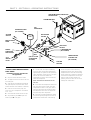
Raypak heaters utilise a finned copper tube
heat exchanger resulting in a low water
content and reduced "stand by" heat losses.
Therefore a circulator pump of sufficient
capacity to match the heater model must be
installed in the system.
Raypak heaters are fitted with Australian Gas
Association approved components and all
heaters in this range are designed to comply with
AS 3814/AG501.
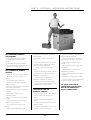
Some models are designed for either indoor or
outdoor installation subject to the appropriate
indoor draft hood or outdoor stackless top
being fitted. It is the responsibility of the
installer to locate the heater in such a manner
that correct operation is obtained.
Check that the correct top for your installation
has been supplied.
RAYPAK will not be held responsible for any
damages which are caused to the appliance
due to its location and caused by means
beyond the control of Raypak, EG High Winds,
Downdraft, Incorrect installation etc.
WARNING:
This appliance must be installed to AS 3500.4
and may require a Backflow Prevention Device
as part of the installation.
All electrical, gas piping, gas connection and
flueing of the heater must only be undertaken
by a properly authorised person. The
installation must comply with local gas, AS
DO NOT INSTALL OR START UP ANY RAYPAK
SUPPLIED PRODUCT THAT HAS BEEN
DAMAGED, WITHOUT FIRST CONSULTING
RAYPAK AS ANY DAMAGE OR FAULTS CAUSED
BY UNAUTHORISED START UP MAY NOT BE
COVERED BY OUR WARRANTY.
HEATER LOCATION AND
CLEARANCES
The heater and any Raypak supplied equipment
should be located so that any possible water
leaks will not cause damage to any adjacent
areas or structures. When such locations
cannot be avoided, it is recommended that a
suitable drain pan, adequately drained, be
installed under the heater.
This pan should be large enough for all of the
equipment and must not restrict combustion
airflow. Any damage caused by water leaks is
the responsibility of the installer.
The heater must be mounted on a level noncombustible base such as a concrete slab,
concrete plinth, steel plate etc. Raypak
heaters and equipment must not be installed
on carpeting.
Any gas or water piping, electrical conduits,
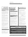
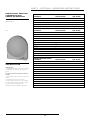
HEATER CLEARANCES
Clearance from non-combustible materials:
Models 507 to 1922
Rear
150mm
Left Side
300mm
Front
750mm
Right Side
300mm
Ceiling
1200mm
Clearance from combustible materials:
Rear
600mm
Left Side
600mm
Front
750mm
Right Side
600mm
Ceiling
1200mm
7
Indoor model heaters must only be installed in
a protective enclosure or properly constructed
plant room with adequate ventilation in
accordance with AS 5601/AG 601 Gas
Installation Code.
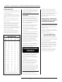
Ventilation shall be via 2 permanent openings
directly to outside, one at an upper level and
one at low level.
The minimum free area provided by each vent
shall be as calculated by using the following
formula, unless otherwise stated in AG 601.
A =1.5 X T
Where A = Minimum free ventilation area (cm2)
T = Total hourly input of all appliances (Mj/h)
Note: The minimum dimension of any opening
shall be 6mm.
Please take the heater location into account
when locating the fresh air vents because any
excessive draft will cause flame disturbance
and probable pilot outage. In some cases
where excessive draft effects the burner, the
risk of major damage is high due to
incomplete combustion.
Installations, which obtain air from a source
other than directly from outside, must comply
with AS 5601/AG601.
Warning: Air supply to the heater room must not
be affected by mechanical exhaust vents located
in other parts of the house or building, such as
kitchen or bathroom fans, spa blowers, etc.
Mechanical exhaust vents may create a negative
Models 2004 to 4224
350mm
600mm
1200mm
600mm
1200mm
600mm
600mm
1200mm
600mm
1200mm