1
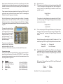
FCC Statement
This device complies with part 15 of the FCC rules. Operation is subject to the
following two conditions: (1) This device may not cause harmful interference, and
(2) this device must accept any interference received, including interference that
may cause undesired operation.
Home Automation Interface Module
Changes or modifications not expressly approved by Goldline Controls could
void the user’s authority to operate this equipment.
PS MODELS
for
Aqua Logic (rev 2.2 or later)
®
NOTE: This equipment has been tested and found to comply with the limits for a
Class B digital device, pursuant to Part 15 of the FCC Rules. These limits are
designed to provide reasonable protection against harmful interference in a residential installation. This equipment generates, uses and can radiate radio frequency energy and, if not installed and used in accordance with the instructions,
may cause harmful interference to radio communications. However, there is no
guarantee that interference will not occur in a particular installation. If this equipment does cause harmful interference to radio or television reception, which can
be determined by turning the equipment off and on, the user is encouraged to try
to correct the interference by one or more of the following measures:
and
PS MODELS
— Reorient or relocate the receiving antenna.
— Increase the separation between the equipment and receiver.
— Connect the equipment into an outlet on a circuit different from that to which
the receiver is connected.
— Consult the dealer or an experienced radio / TV technician for help.
Industry Canada Statement
This Class B digital apparatus complies with Canadian ICES-003.
Cet appareil numérique de la classe B est conforme à la norme NMB-003 du Canada.
The term “IC” before the certification / registration number only signifies that the
Industry Canada technical specifications were met.
AQ-CO-SERIAL
User Manual
G
Copyright © 2008 Goldine Controls
092329C
LDLINE
C ON TROLS
www.goldlinecontrols.com
Introduction: The AQ-CO-SERIAL is a serial home automation module that
provides a command set which enables any attached system to fully emulate
an Aqua Logic PS pool control running software rev 2.2 or later or any Pro Logic
PS pool control. Thus, buttons can be transmitted, and the Aqua Logic PS/Pro
Logic PS LED and messaging display states are returned.
A complete description of the operation of an Aqua Logic PS or Pro Logic PS
can be found in the user manuals at www.goldlinecontrols.com.
Tools Needed:
-RS232 Cable (Straight through Male to Female DB9 Cable, 25' max)
-Four conductor low voltage control wire up to 100 feet (RS-485 wiring)
-Aqua Logic PS model pool control with Rev: 2.2 or later firmware
OR
Pro Logic PS model pool control
Functionality:
The AQ-CO-SERIAL interconnects an RS-232 bus from any Home Automation
system with the Aqua Logic PS/Pro Logic PS using the powered RS-485. A
typical system is shown below.
RS485
& Power
RS232
LIMITED WARRANTY Goldline warrants its Aqua Rite, Aqua Rite Pro, Aqua Trol, Aqua Logic
and Pro Logic products (products with Goldline part numbers starting with AQ-RITE-, AQ-RTPRO, AQ-TROL-, AQ-LOGIC-, AQL-P-, AQL-PS-, AQL-CL-, PL-P-, PL-PS-, and HPC-2) to be
free from defects in material or workmanship, under normal use and service:
For three years from the date of the initial system installation on private, residential swimming
pools within the USA or Canada and one year from the date of initial system installation on
commercial installations, installations outside of the USA or Canada and for any replacement
parts or accessory products, provided they are installed in accordance with the Goldline installation instructions and specifications provided with the product. If written proof of the date of the
initial system installation is not provided to Goldline, the manufacturing datecode on the Aqua
Rite, Aqua Rite Pro, Aqua Trol, Aqua Logic and Pro Logic electronics unit will be the sole
determinant of the date of the initial system installation.
For residential installations in USA or Canada: If a product is defective in workmanship or
materials and is removed and returned freight prepaid within three (3) years after the date of the
initial system installation, Goldline will, at its option, either repair or replace the defective
product and return it freight prepaid.
For commercial installations, installations outside the USA and Canada, and accessory products
and replacement parts: If a product is defective in workmanship or materials and is removed and
returned freight prepaid within one (1) year after the date of the initial system installation,
Goldline will, at its option, either repair or replace the defective product and return it freight
prepaid.
Contact any Goldline dealer or contact Goldline at 61 Whitecap Drive, North Kingstown, RI
02852 for warranty service. The costs incurred in removal and/or reinstallation of the product
are NOT covered under this warranty. Some states do not allow limitations on how long an
implied warranty lasts, so the above limitation may not apply to you.
WARRANTY EXCLUSIONS:
1.
Material supplied or workmanship performed by others in process of installation.
2.
Damage resulting from improper installation including installation on pools larger
than the product rating.
3.
Problems resulting from failure to operate the product(s) in accordance with the
recommended instructions contained in product’s owners manual(s).
4.
Problems resulting from failure to maintain pool water chemistry in accordance with
the recommendations in the owners manual(s).
Power:
The AQ-CO-SERIAL is powered via RS485 from the Aqua Logic PS/Pro Logic
PS control.
Typical Setup:
The RS-232 end is connected to the Home Automation System and the RS485
end is connected to the Aqua Logic PS/Pro Logic PS. The AQ-CO-SERIAL
enclosure is 5" X 5.25" X 1.25" and is designed to be mounted indoors only.
5.
Problems resulting from tampering, accident, abuse, negligence, unauthorized repairs
or alternations, fire, flood, lightning, freezing, external water, degradation of natural stone used
in or immediately adjacent to a pool or spa, war or acts of God.
DISCLAIMER. THE EXPRESS LIMITED WARRANTY ABOVE CONSTITUTES THE ENTIRE WARRANTY OF GOLDLINE WITH RESPECT TO ITS POOL AUTOMATION AND
CHLORINATION PRODUCTS AND IS IN LIEU OF ALL OTHER WARRANTIES, EXPRESSED OR IMPLIED, INCLUDING WARRANTIES OF MERCHANTABILITY OR FITNESS FOR A PARTICULAR PURPOSE. THIS WARRANTY GIVES YOU SPECIFIC
LEGAL RIGHTS, AND YOU MAY ALSO HAVE OTHER RIGHTS WHICH VARY FROM
STATE TO STATE. IN NO EVENT SHALL GOLDLINE BE RESPONSIBLE FOR ANY
CONSEQUENTIAL, SPECIAL OR INCIDENTAL DAMAGES OF ANY NATURE WHATSOEVER, INCLUDING, BUT NOT LIMITED TO, PERSONAL INJURY, PROPERTY DAMAGE, DAMAGE TO OR LOSS OF EQUIPMENT, LOST PROFITS OR REVENUE, COSTS
OF RENTING REPLACEMENTS, AND OTHER ADDITIONAL EXPENSES, EVEN IF THE
SELLER HAD BEEN ADVISED OF THE POSSIBILITY OF SUCH DAMAGES. SOME
STATES DO NOT ALLOW THE EXCLUSION OF LIMITATION OF INCIDENTAL OR
CONSEQUENTIAL DAMAGES, SO THE ABOVE LIMITATION OR EXCLUSION MAY
NOT APPLY TO YOU.
NO WHOLESALER, AGENT, DEALER, CONTRACTOR OR OTHER PERSON IS AUTHORIZED TO GIVE ANY WARRANTY ON BEHALF OF GOLDLINE.
THIS WARRANTY IS VOID IF THE PRODUCT HAS BEEN ALTERED IN ANY WAY AFTER
LEAVING THE FACTORY.
1
10
Response:
None
For PS Models, in order to make a character blink, the eighth bit of the corresponding character is set. Refer to the following example:
'1' = 31H = 00110001, '1' does not blink
'1' = B1H = 10110001, '1' blinks
AQ-CO-SERIAL
PCB
(From:AQ-CO-SERIAL To:HA)
(05H)
Command Beep Time
Response:
None
After the Configuration Menu is unlocked, Aqua Logic PS/Pro Logic PS sends
the Beeper command indicating the occurrence. The Update Key Pad Release command for the Unlock Configuration Menu has to be sent at this
point.
Special Characters:
The symbol “Degree” is sent as an “underscore _”. The “Degree” being 0xDF,
has the eighth bit set and to make sure that it’s not mistaken as blinking its
being sent as Underscore (0x5F). For example: To display “Air Temp 99°F”,
the packet will be “Air Temp 99_F”.
Error Conditions:
If the AQ-CO-SERIAL is not communicating with Aqua Logic PS/Pro Logic PS
a Display command will be sent stating “Pro Logic Comm Bus Communication Lost”.
Product Support
For questions or support on applying the above command language, please
send an email to [email protected].
9
To Home
Automation
System
J4
1 Aqua Logic
2
or
3 Pro Logic
4
J2
RS232
J3
1
2
3
4
RS485
Command: Beeper
Refer to the diagram below. The Home Automation system is connected to
the RS232 (J3) connector. To communicate with Aqua Logic PS/Pro Logic
PS, the connectors J2 or J4 are used. (J2 and J4 are connected in parallel
internally).
The Aqua Logic PS/Pro Logic PS communicates to its peripherals via a half
duplex asynchronous RS-485 link that also supplies DC power. All peripherals
are wired in parallel on this bus. The Aqua Logic PS/Pro Logic PS is the
master of the bus, and devices only transmit when queried. For example, to
receive a keypress from any one of the remote controls, the Aqua Logic PS/Pro
Logic PS requests pending keys every 100 ms, and then listens for an answer.
If any remote control has a pending keypress, it is immediately sent back to
the Aqua Logic PS/Pro Logic PS.
The AQ-CO-SERIAL relieves the Home Automation system from having to respond to the Aqua Logic PS/Pro Logic PS timing and command response
requirements. It is a simple board with a processor, a ground isolated RS232
interface via DB9 connector, and a terminal strip for connection to the Aqua
Logic PS/Pro Logic PS bus. It performs as a slave to Aqua Logic PS/Pro Logic
PS and as a bi-directional interface to the Home Automation System. All the
commands needed to emulate a remote control are supported: sending a
keypress to the Aqua Logic PS/Pro Logic PS, and receiving text and LED
status.
The Aqua Logic PS/Pro Logic PS-16
has 16 internal relays. The PS-4 and
PS-8-V has 4 relays. The PS-8 and
PS-16-V has 8 relays. The “V” models double the AUX buttons for use
as macro buttons called “groups”. The
image on page 2 is of a PS-16 remote with all keys un-labeled. The
remote is shipped with adhesive labels which allow customization of the
keyboard. The same list of labels are
available in the system software so
that a relay or valve can be more appropriately named.
2
Shown below is a labeled remote control to a Pro Logic PS pool control. Note
that labels have been placed over the generic names to make the keys human
readable. In this case, the Pool Filter, Gas Heater, Spa Filter and Water Feature are all turned on.
Bit 0
Bit 1
These names also have been selected in the Aqua Logic PS/Pro Logic PS
configuration menu so that when the user presses “Spa Jets” a message says
“Spa Jets Turned On” appears on the display.
Display Software
Revision
Note that buttons may not respond under certain conditions. For example,
pressing “Cleaner” while the Pool Filter is OFF, will result in the message
“Interlock prevents turn on” being displayed and the LED will not light up.
There are many such special features and interlocks in the Aqua Logic PS/Pro
Logic PS.
The menu button selects the Aqua
Logic PS/Pro Logic PS menus.
The navigation keys surrounding
the menu button allows movement
through sub menus (“<“ and “>”)
and value changes (“+” and “-”).
All feedback is via the 2 x 20 alphanumeric display.
The revision or the whole display can be replaced by the HA Developer. The Aqua Logic PS/Pro Logic PS display will show its software
revision as shown below:
Display Software
Local-08 r4.00
Bit 2
This is an Aqua Logic PS/Pro Logic PS feature only. Following is a
description of how it is used on these pool controls. In Settings Menu,
when “Display Light” is selected, the Update Display Command is
sent as:
Display Light
Note that the second line is blank. And the Bit 2 will be set to 1. The
actual Aqua Logic PS/Pro Logic PS display will show its current mode:
The menus are mainly used to
configure the pool and change
temperature setpoints. Most user
interaction is via the direct-access keys in the lower half of the control.
Command overview:
These are the standard commands which are used for communicating between the Home Automation (HA) and the AQ-CO-SERIAL. To keep this system simple, these commands are very similar to the commands used on the
Aqua Logic PS/Pro Logic PS bus.
Hex
01
02
03
04
05
Not used currently.
The Revision has to be filled in by the Home Automation System if Bit
1 is set. For example: In the Diagnostics Menu, when “Display Software” is selected, the Update Display Command is sent as below,
(with Bit 1 set to 1):
Command
Update Key Pad Press
Update Key Pad Release
Update LEDs
Update Display
Beeper
(HA to AQ-CO-SERIAL)
(HA to AQ-CO-SERIAL)
(AQ-CO-SERIAL to HA)
(AQ-CO-SERIAL to HA)
(AQ-CO-SERIAL to HA)
Display Light
Always ON
Bit 3
or
Display Light
On for 60 seconds
This is also an Aqua Logic PS/Pro Logic PS feature only. Following is
a description of how it is used on these pool controls. In Settings
Menu, when “Beeper” is selected, the Update Display Command is
always sent as:
Beeper
Enabled
Bit 3 is set to 1. The actual Aqua Logic PS/Pro Logic PS display will
show its current mode:
Beeper
Enabled
or
Beeper
Disabled
Note: Bits1, 2, 3 can be implemented if desired.
3
8
Command: Update LEDs
(From:AQ-CO-SERIAL To:HA)
The AQ-CO-SERIAL will send this command whenever a change of any LED
state occurs.
(03H)
Command LEDs 1
LEDs 2
Byte
LEDs 1
LEDs 1
LEDs 1
LEDs 1
LEDs 1
LEDs 1
LEDs 1
LEDs 1
Bit
0
1
2
3
4
5
6
7
LED
Heater1
Valve3
Check System
Pool
Spa
Filter
Lights
Aux1
Byte
LEDs 2
LEDs 2
LEDs 2
LEDs 2
LEDs 2
LEDs 2
LEDs 2
LEDs 2
Bit
0
1
2
3
4
5
6
7
LED
Aux2
(Service)
Aux3
Aux4
Aux5
Aux6
Valve4/Heater2
Spillover
Byte
LEDs 3
LEDs 3
LEDs 3
LEDs 3
LEDs 3
LEDs 3
LEDs 3
LEDs 3
Bit
0
1
2
3
4
5
6
7
LED
System off
Aux7
Aux8
Aux9
Aux10
Aux11
Aux12
Aux13
Byte
LEDs 4
LEDs 4
LEDs 4
LEDs 4
LEDs 4
LEDs 4
LEDs 4
LEDs 4
Bit
0
1
2
3
4
5
6
7
LED
Aux14
Super Chlorinate
LEDs 3
Blink
LEDs 4
Blink
LEDs 1
Blink
LEDs 2
Blink
LEDs 3
Blink
LEDs 4
Thus, for the home automation system to send a key, a Press and a Release
command are required. The Aqua Logic PS/Pro Logic PS will always react to
the “Press” command. In some menus where value scrolling is supported, a
delay between the press and release greater than two seconds will start the
value scrolling. A common use of scrolling is setting the temperature of the
heater or the chlorination rate of the chlorine generator.
The AQ-CO-SERIAL will forward an Update LED or Update Display command
if a change in content is detected since the previous transmission of such
commands. These commands are sent once every 2 seconds, even if no
information has changed.
Framing and Rate: Asynchronous serial mode is used with the following
character format: 1 start bit, 8 data bits, no parity and 2 stop bits. The data
rate is 19.2 kbps. The basic frame structure used is shown below.
Each frame begins with a DLE (10H) and STX (02H) character start sequence,
followed by a 2 to 61 byte long Command/Data field, a 2-byte Checksum and
a DLE (10H) and ETX (03H) character end sequence.
The DLE, STX and Command/Data fields are added together to provide the 2byte Checksum. If any of the bytes of the Command/Data Field or Checksum
are equal to the DLE character (10H), a NULL character (00H) is inserted into
the transmitted data stream immediately after that byte. That NULL character
must then be removed by the receiver.
If an LED bit is a 1, then that LED is on. If the LED bit is a 1 and it’s associated Blink LED bit is a 1, then that LED should blink at a rate of once per
second (half second on/half second off).
Response:
None
The Command and Data Fields for the various commands and expected responses are as follows:
(10H)
DLE
(02H)
STX
Command/Data
Checksum MSB
Command: Update Display
(From:AQ-CO-SERIAL To:HA)
The AQ-CO-SERIAL will send this command whenever a change of display
text occurs. This command is sent once every 2 seconds, even if no information has changed.
The Display Flags are defined as follows:
Bit 0:
Blink Display Selection (P-4 Only)
Bit 1:
Display Revision
Bits 2:
Display Backlight Time
Bits 3:
Display Beeper Status
Bits 4-7:
Reserved
7
(0=No, 1=Yes)
(0=No, 1=Yes)
(0=No, 1=Yes)
(0=No, 1=Yes)
4
Checksum LSB
(10H)
DLE
(03H)
ETX
Command: Update Key Pad Press
(From:HA, To:AQ-CO-SERIAL)
Use this command to simulate the user pressing a button. Upon receipt of a
Key Press, the AQ-CO-SERIAL first reports the press action, and then reports
that the key is being held down until a Key Pad Release is received. Note, if
any “pressed” keys are not released within 20 seconds the AQ-CO-SERIAL
assumes loss of communication and clears all the key presses.
(01H)
Command
Data
Data ( in Hexadecimal)
01
">"
02
Menu
03
"<"
04
Service/System off
05
06
07
08
"-"
"+"
Pool/Spa/Spillover
Filter
09
10
11
12
13
14
15
16
Lights
Aux1
Aux2
Aux3
Aux4
Aux5
Aux6
Aux7
17
18
19
20
21
22
23
24
Valve3
Valve4/Heater2
Heater1
Aux8
Aux9
Aux10
Aux11
Aux12
25
26
27
28
Aux13
Aux14
Super Chlorinate
Unlock Configuration Menu*
Command: Update Key Pad Release (From:HA, To:AQ-CO-SERIAL)
Use this command to simulate the user releasing a button.
(02H)
Command
Data
Data ( in Hexadecimal)
01
">"
02
Menu
03
"<"
04
Service/System off
05
06
07
08
"- "
"+"
Pool/Spa/Spillover
Filter
09
10
11
12
13
14
15
16
Lights
Aux1
Aux2
Aux3
Aux4
Aux5
Aux6
Aux7
17
18
19
20
21
22
23
24
Valve3
Valve4/Heater2
Heater1
Aux8
Aux9
Aux10
Aux11
Aux12
25
26
27
28
Aux13
Aux14
Super Chlorinate
Unlock Configuration Menu
Example: When the ">" key is released, the command is:
10H
02H
02H
01H
00H 15H
10H
DLE
STX
CMD
DATA
Checksum
DLE
*Note: In order to unlock Configuration menu, the display has to show “Configuration Menu-Locked”, otherwise the unlock command will be ignored.
5
6
03H
ETX
Command: Update LEDs
(From:AQ-CO-SERIAL To:HA)
The AQ-CO-SERIAL will send this command whenever a change of any LED
state occurs.
(03H)
Command LEDs 1
LEDs 2
Byte
LEDs 1
LEDs 1
LEDs 1
LEDs 1
LEDs 1
LEDs 1
LEDs 1
LEDs 1
Bit
0
1
2
3
4
5
6
7
LED
Heater1
Valve3
Check System
Pool
Spa
Filter
Lights
Aux1
Byte
LEDs 2
LEDs 2
LEDs 2
LEDs 2
LEDs 2
LEDs 2
LEDs 2
LEDs 2
Bit
0
1
2
3
4
5
6
7
LED
Aux2
(Service)
Aux3
Aux4
Aux5
Aux6
Valve4/Heater2
Spillover
Byte
LEDs 3
LEDs 3
LEDs 3
LEDs 3
LEDs 3
LEDs 3
LEDs 3
LEDs 3
Bit
0
1
2
3
4
5
6
7
LED
System off
Aux7
Aux8
Aux9
Aux10
Aux11
Aux12
Aux13
Byte
LEDs 4
LEDs 4
LEDs 4
LEDs 4
LEDs 4
LEDs 4
LEDs 4
LEDs 4
Bit
0
1
2
3
4
5
6
7
LED
Aux14
Super Chlorinate
LEDs 3
Blink
LEDs 4
Blink
LEDs 1
Blink
LEDs 2
Blink
LEDs 3
Blink
LEDs 4
Thus, for the home automation system to send a key, a Press and a Release
command are required. The Aqua Logic PS/Pro Logic PS will always react to
the “Press” command. In some menus where value scrolling is supported, a
delay between the press and release greater than two seconds will start the
value scrolling. A common use of scrolling is setting the temperature of the
heater or the chlorination rate of the chlorine generator.
The AQ-CO-SERIAL will forward an Update LED or Update Display command
if a change in content is detected since the previous transmission of such
commands. These commands are sent once every 2 seconds, even if no
information has changed.
Framing and Rate: Asynchronous serial mode is used with the following
character format: 1 start bit, 8 data bits, no parity and 2 stop bits. The data
rate is 19.2 kbps. The basic frame structure used is shown below.
Each frame begins with a DLE (10H) and STX (02H) character start sequence,
followed by a 2 to 61 byte long Command/Data field, a 2-byte Checksum and
a DLE (10H) and ETX (03H) character end sequence.
The DLE, STX and Command/Data fields are added together to provide the 2byte Checksum. If any of the bytes of the Command/Data Field or Checksum
are equal to the DLE character (10H), a NULL character (00H) is inserted into
the transmitted data stream immediately after that byte. That NULL character
must then be removed by the receiver.
If an LED bit is a 1, then that LED is on. If the LED bit is a 1 and it’s associated Blink LED bit is a 1, then that LED should blink at a rate of once per
second (half second on/half second off).
Response:
None
The Command and Data Fields for the various commands and expected responses are as follows:
(10H)
DLE
(02H)
STX
Command/Data
Checksum MSB
Command: Update Display
(From:AQ-CO-SERIAL To:HA)
The AQ-CO-SERIAL will send this command whenever a change of display
text occurs. This command is sent once every 2 seconds, even if no information has changed.
The Display Flags are defined as follows:
Bit 0:
Blink Display Selection (P-4 Only)
Bit 1:
Display Revision
Bits 2:
Display Backlight Time
Bits 3:
Display Beeper Status
Bits 4-7:
Reserved
7
(0=No, 1=Yes)
(0=No, 1=Yes)
(0=No, 1=Yes)
(0=No, 1=Yes)
4
Checksum LSB
(10H)
DLE
(03H)
ETX
Shown below is a labeled remote control to a Pro Logic PS pool control. Note
that labels have been placed over the generic names to make the keys human
readable. In this case, the Pool Filter, Gas Heater, Spa Filter and Water Feature are all turned on.
Bit 0
Bit 1
These names also have been selected in the Aqua Logic PS/Pro Logic PS
configuration menu so that when the user presses “Spa Jets” a message says
“Spa Jets Turned On” appears on the display.
Display Software
Revision
Note that buttons may not respond under certain conditions. For example,
pressing “Cleaner” while the Pool Filter is OFF, will result in the message
“Interlock prevents turn on” being displayed and the LED will not light up.
There are many such special features and interlocks in the Aqua Logic PS/Pro
Logic PS.
The menu button selects the Aqua
Logic PS/Pro Logic PS menus.
The navigation keys surrounding
the menu button allows movement
through sub menus (“<“ and “>”)
and value changes (“+” and “-”).
All feedback is via the 2 x 20 alphanumeric display.
The revision or the whole display can be replaced by the HA Developer. The Aqua Logic PS/Pro Logic PS display will show its software
revision as shown below:
Display Software
Local-08 r4.00
Bit 2
This is an Aqua Logic PS/Pro Logic PS feature only. Following is a
description of how it is used on these pool controls. In Settings Menu,
when “Display Light” is selected, the Update Display Command is
sent as:
Display Light
Note that the second line is blank. And the Bit 2 will be set to 1. The
actual Aqua Logic PS/Pro Logic PS display will show its current mode:
The menus are mainly used to
configure the pool and change
temperature setpoints. Most user
interaction is via the direct-access keys in the lower half of the control.
Command overview:
These are the standard commands which are used for communicating between the Home Automation (HA) and the AQ-CO-SERIAL. To keep this system simple, these commands are very similar to the commands used on the
Aqua Logic PS/Pro Logic PS bus.
Hex
01
02
03
04
05
Not used currently.
The Revision has to be filled in by the Home Automation System if Bit
1 is set. For example: In the Diagnostics Menu, when “Display Software” is selected, the Update Display Command is sent as below,
(with Bit 1 set to 1):
Command
Update Key Pad Press
Update Key Pad Release
Update LEDs
Update Display
Beeper
(HA to AQ-CO-SERIAL)
(HA to AQ-CO-SERIAL)
(AQ-CO-SERIAL to HA)
(AQ-CO-SERIAL to HA)
(AQ-CO-SERIAL to HA)
Display Light
Always ON
Bit 3
or
Display Light
On for 60 seconds
This is also an Aqua Logic PS/Pro Logic PS feature only. Following is
a description of how it is used on these pool controls. In Settings
Menu, when “Beeper” is selected, the Update Display Command is
always sent as:
Beeper
Enabled
Bit 3 is set to 1. The actual Aqua Logic PS/Pro Logic PS display will
show its current mode:
Beeper
Enabled
or
Beeper
Disabled
Note: Bits1, 2, 3 can be implemented if desired.
3
8
Response:
None
For PS Models, in order to make a character blink, the eighth bit of the corresponding character is set. Refer to the following example:
'1' = 31H = 00110001, '1' does not blink
'1' = B1H = 10110001, '1' blinks
AQ-CO-SERIAL
PCB
(From:AQ-CO-SERIAL To:HA)
(05H)
Command Beep Time
Response:
None
After the Configuration Menu is unlocked, Aqua Logic PS/Pro Logic PS sends
the Beeper command indicating the occurrence. The Update Key Pad Release command for the Unlock Configuration Menu has to be sent at this
point.
Special Characters:
The symbol “Degree” is sent as an “underscore _”. The “Degree” being 0xDF,
has the eighth bit set and to make sure that it’s not mistaken as blinking its
being sent as Underscore (0x5F). For example: To display “Air Temp 99°F”,
the packet will be “Air Temp 99_F”.
Error Conditions:
If the AQ-CO-SERIAL is not communicating with Aqua Logic PS/Pro Logic PS
a Display command will be sent stating “Pro Logic Comm Bus Communication Lost”.
Product Support
For questions or support on applying the above command language, please
send an email to [email protected].
9
To Home
Automation
System
J4
1 Aqua Logic
2
or
3 Pro Logic
4
J2
RS232
J3
1
2
3
4
RS485
Command: Beeper
Refer to the diagram below. The Home Automation system is connected to
the RS232 (J3) connector. To communicate with Aqua Logic PS/Pro Logic
PS, the connectors J2 or J4 are used. (J2 and J4 are connected in parallel
internally).
The Aqua Logic PS/Pro Logic PS communicates to its peripherals via a half
duplex asynchronous RS-485 link that also supplies DC power. All peripherals
are wired in parallel on this bus. The Aqua Logic PS/Pro Logic PS is the
master of the bus, and devices only transmit when queried. For example, to
receive a keypress from any one of the remote controls, the Aqua Logic PS/Pro
Logic PS requests pending keys every 100 ms, and then listens for an answer.
If any remote control has a pending keypress, it is immediately sent back to
the Aqua Logic PS/Pro Logic PS.
The AQ-CO-SERIAL relieves the Home Automation system from having to respond to the Aqua Logic PS/Pro Logic PS timing and command response
requirements. It is a simple board with a processor, a ground isolated RS232
interface via DB9 connector, and a terminal strip for connection to the Aqua
Logic PS/Pro Logic PS bus. It performs as a slave to Aqua Logic PS/Pro Logic
PS and as a bi-directional interface to the Home Automation System. All the
commands needed to emulate a remote control are supported: sending a
keypress to the Aqua Logic PS/Pro Logic PS, and receiving text and LED
status.
The Aqua Logic PS/Pro Logic PS-16
has 16 internal relays. The PS-4 and
PS-8-V has 4 relays. The PS-8 and
PS-16-V has 8 relays. The “V” models double the AUX buttons for use
as macro buttons called “groups”. The
image on page 2 is of a PS-16 remote with all keys un-labeled. The
remote is shipped with adhesive labels which allow customization of the
keyboard. The same list of labels are
available in the system software so
that a relay or valve can be more appropriately named.
2
Introduction: The AQ-CO-SERIAL is a serial home automation module that
provides a command set which enables any attached system to fully emulate
an Aqua Logic PS pool control running software rev 2.2 or later or any Pro Logic
PS pool control. Thus, buttons can be transmitted, and the Aqua Logic PS/Pro
Logic PS LED and messaging display states are returned.
A complete description of the operation of an Aqua Logic PS or Pro Logic PS
can be found in the user manuals at www.goldlinecontrols.com.
Tools Needed:
-RS232 Cable (Straight through Male to Female DB9 Cable, 25' max)
-Four conductor low voltage control wire up to 100 feet (RS-485 wiring)
-Aqua Logic PS model pool control with Rev: 2.2 or later firmware
OR
Pro Logic PS model pool control
Functionality:
The AQ-CO-SERIAL interconnects an RS-232 bus from any Home Automation
system with the Aqua Logic PS/Pro Logic PS using the powered RS-485. A
typical system is shown below.
RS485
& Power
RS232
LIMITED WARRANTY Goldline warrants its Aqua Rite, Aqua Rite Pro, Aqua Trol, Aqua Logic
and Pro Logic products (products with Goldline part numbers starting with AQ-RITE-, AQ-RTPRO, AQ-TROL-, AQ-LOGIC-, AQL-P-, AQL-PS-, AQL-CL-, PL-P-, PL-PS-, and HPC-2) to be
free from defects in material or workmanship, under normal use and service:
For three years from the date of the initial system installation on private, residential swimming
pools within the USA or Canada and one year from the date of initial system installation on
commercial installations, installations outside of the USA or Canada and for any replacement
parts or accessory products, provided they are installed in accordance with the Goldline installation instructions and specifications provided with the product. If written proof of the date of the
initial system installation is not provided to Goldline, the manufacturing datecode on the Aqua
Rite, Aqua Rite Pro, Aqua Trol, Aqua Logic and Pro Logic electronics unit will be the sole
determinant of the date of the initial system installation.
For residential installations in USA or Canada: If a product is defective in workmanship or
materials and is removed and returned freight prepaid within three (3) years after the date of the
initial system installation, Goldline will, at its option, either repair or replace the defective
product and return it freight prepaid.
For commercial installations, installations outside the USA and Canada, and accessory products
and replacement parts: If a product is defective in workmanship or materials and is removed and
returned freight prepaid within one (1) year after the date of the initial system installation,
Goldline will, at its option, either repair or replace the defective product and return it freight
prepaid.
Contact any Goldline dealer or contact Goldline at 61 Whitecap Drive, North Kingstown, RI
02852 for warranty service. The costs incurred in removal and/or reinstallation of the product
are NOT covered under this warranty. Some states do not allow limitations on how long an
implied warranty lasts, so the above limitation may not apply to you.
WARRANTY EXCLUSIONS:
1.
Material supplied or workmanship performed by others in process of installation.
2.
Damage resulting from improper installation including installation on pools larger
than the product rating.
3.
Problems resulting from failure to operate the product(s) in accordance with the
recommended instructions contained in product’s owners manual(s).
4.
Problems resulting from failure to maintain pool water chemistry in accordance with
the recommendations in the owners manual(s).
Power:
The AQ-CO-SERIAL is powered via RS485 from the Aqua Logic PS/Pro Logic
PS control.
Typical Setup:
The RS-232 end is connected to the Home Automation System and the RS485
end is connected to the Aqua Logic PS/Pro Logic PS. The AQ-CO-SERIAL
enclosure is 5" X 5.25" X 1.25" and is designed to be mounted indoors only.
5.
Problems resulting from tampering, accident, abuse, negligence, unauthorized repairs
or alternations, fire, flood, lightning, freezing, external water, degradation of natural stone used
in or immediately adjacent to a pool or spa, war or acts of God.
DISCLAIMER. THE EXPRESS LIMITED WARRANTY ABOVE CONSTITUTES THE ENTIRE WARRANTY OF GOLDLINE WITH RESPECT TO ITS POOL AUTOMATION AND
CHLORINATION PRODUCTS AND IS IN LIEU OF ALL OTHER WARRANTIES, EXPRESSED OR IMPLIED, INCLUDING WARRANTIES OF MERCHANTABILITY OR FITNESS FOR A PARTICULAR PURPOSE. THIS WARRANTY GIVES YOU SPECIFIC
LEGAL RIGHTS, AND YOU MAY ALSO HAVE OTHER RIGHTS WHICH VARY FROM
STATE TO STATE. IN NO EVENT SHALL GOLDLINE BE RESPONSIBLE FOR ANY
CONSEQUENTIAL, SPECIAL OR INCIDENTAL DAMAGES OF ANY NATURE WHATSOEVER, INCLUDING, BUT NOT LIMITED TO, PERSONAL INJURY, PROPERTY DAMAGE, DAMAGE TO OR LOSS OF EQUIPMENT, LOST PROFITS OR REVENUE, COSTS
OF RENTING REPLACEMENTS, AND OTHER ADDITIONAL EXPENSES, EVEN IF THE
SELLER HAD BEEN ADVISED OF THE POSSIBILITY OF SUCH DAMAGES. SOME
STATES DO NOT ALLOW THE EXCLUSION OF LIMITATION OF INCIDENTAL OR
CONSEQUENTIAL DAMAGES, SO THE ABOVE LIMITATION OR EXCLUSION MAY
NOT APPLY TO YOU.
NO WHOLESALER, AGENT, DEALER, CONTRACTOR OR OTHER PERSON IS AUTHORIZED TO GIVE ANY WARRANTY ON BEHALF OF GOLDLINE.
THIS WARRANTY IS VOID IF THE PRODUCT HAS BEEN ALTERED IN ANY WAY AFTER
LEAVING THE FACTORY.
1
10
FCC Statement
This device complies with part 15 of the FCC rules. Operation is subject to the
following two conditions: (1) This device may not cause harmful interference, and
(2) this device must accept any interference received, including interference that
may cause undesired operation.
Home Automation Interface Module
Changes or modifications not expressly approved by Goldline Controls could
void the user’s authority to operate this equipment.
PS MODELS
for
Aqua Logic (rev 2.2 or later)
®
NOTE: This equipment has been tested and found to comply with the limits for a
Class B digital device, pursuant to Part 15 of the FCC Rules. These limits are
designed to provide reasonable protection against harmful interference in a residential installation. This equipment generates, uses and can radiate radio frequency energy and, if not installed and used in accordance with the instructions,
may cause harmful interference to radio communications. However, there is no
guarantee that interference will not occur in a particular installation. If this equipment does cause harmful interference to radio or television reception, which can
be determined by turning the equipment off and on, the user is encouraged to try
to correct the interference by one or more of the following measures:
and
PS MODELS
— Reorient or relocate the receiving antenna.
— Increase the separation between the equipment and receiver.
— Connect the equipment into an outlet on a circuit different from that to which
the receiver is connected.
— Consult the dealer or an experienced radio / TV technician for help.
Industry Canada Statement
This Class B digital apparatus complies with Canadian ICES-003.
Cet appareil numérique de la classe B est conforme à la norme NMB-003 du Canada.
The term “IC” before the certification / registration number only signifies that the
Industry Canada technical specifications were met.
AQ-CO-SERIAL
User Manual
G
Copyright © 2008 Goldine Controls
092329C
LDLINE
C ON TROLS
www.goldlinecontrols.com