1
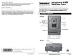
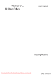
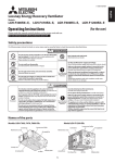
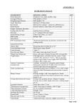
TECHNICAL MANUAL FOR NORTH AMERICA
LGH-F-RX5-E
1.SPECIFICATIONS.....................................................................................................................................................ERV-3
2. DIMENSION DRAWINGS.........................................................................................................................................ERV-4
3. WIRING DIAGRAMS.................................................................................................................................................ERV-6
3-1. WIRING DIAGRAMS.......................................................................................................................................ERV-6
3-2. CIRCUIT BOARD DIAGRAMS.........................................................................................................................ERV-8
4. SOUND NC CURVES...............................................................................................................................................ERV-9
5. EFFICIENCY AND FAN CURVES........................................................................................................................... ERV-11
5-1. EFFICIENCY CALCULATION........................................................................................................................ ERV-11
5-2. EFFICIENCY CHART AND FAN CURVES....................................................................................................ERV-12
5-3. EXHAUST FLOW CORRECTION..................................................................................................................ERV-14
Models
Lossnay Unit
5-4. EXHAUST FLOW CORRECTIONS TABULATED..........................................................................................ERV-15
LGH-F300RX5-E
6. EXTERNAL CONTROL
OF FAN 5SPEED
/ CO2 CONTROL...................................................................................ERV-16
-E
LGH-F470RX
LGH-F600RX5-E
7. ENTERING AIR TEMPERATURE
OPERATING RANGE.......................................................................................ERV-17
LGH-F1200RX5-E
8. VENTILATION CONSIDERATIONS........................................................................................................................ERV-18
Lossnay Remote Controller
9.INSTALLATION.......................................................................................................................................................ERV-19
PZ-60DR-E
PZ-41SLB-E
9-2. SUPPLEMENTAL
FAN DEVICES..................................................................................................................ERV-20
PZ-52SF-E
9-3. DUCTWORK INSTALLATION WITH LOSSNAY®..........................................................................................ERV-21
9-1. ORIENTATION...............................................................................................................................................ERV-19
10.FROST PREVENTIONS.........................................................................................................................................ERV-25
11.VENTILATION MODES...........................................................................................................................................ERV-26
11-1. VENTILATION MODE...................................................................................................................................ERV-26
11-2. DAMPER CONTROL FOR EACH SYSTEM.................................................................................................ERV-27
11-3. BYPASS VENTILATION PROHIBITED.........................................................................................................ERV-28
11-4. AUTOMATIC VENTILATION ALGORITHM TEMPERATURE MAP...............................................................ERV-28
11-5. VENTILATION MODE CHANGE RECOMMENDATION DISPLAY...............................................................ERV-29
2012 LGH-F-RX5-E (June 2013)
© 2013 Mitsubishi Electric US, Inc.
ERV-1
TECHNICAL MANUAL FOR NORTH AMERICA
LOSSNAY is a perfect combination of heat recovery and ventilation, which is a leading edge product in the ventilation and
air-conditioning field.
The LOSSNAY core is a special preserved paper made cross-flow and plate-fin structure, which is referable below.
32°F(0°C)
Outside air exhaust
(outdoor heating / cooling air)
Outside cool air (outdoor)
Models
68°F
Lossnay Unit
LGH-F300RX5-E
LGH-F470RX5-E
LGH-F600RX5-E
LGH-F1200RX5-E
(20°C)
Outside air induction
(outdoor air)
55.6°F(13.1°C)
Lossnay Remote Controller
PZ-60DR-E
PZ-41SLB-E
* LGH-F300RX5-E
(High fan speed)
PZ-52SF-E
CITY MULTI can combine LOSSNAY into the air conditioning system, performing the best solution to ventilation and air-conditioning.
Outdoor unit
Indoor unit
Indoor unit
Lossnay
Remote controller
Line up of LOSSNAY units
ERV-2
LGH-F300RX5-E
LGH-F470RX5-E
LGH-F600RX5-E
LGH-F1200RX5-E
300 CFM
470 CFM
600 CFM
1200 CFM
1-phase 208-230V, 60Hz
1-phase 208-230V, 60Hz
1-phase 208-230V, 60Hz
1-phase 208-230V, 60Hz
2012 LGH-F-RX5-E (June 2013)
© 2013 Mitsubishi Electric US, Inc.
1. SPECIFICATIONS
LGH-F300RX5-E
Model
Power source
Ventilation mode
Speed
Current (A)
Input (W)
Air volume
(CFM)
(In. W.G.)
External static pressure
Temperature recovery efficiency (%)
Heating
Enthalpy recovery
efficiency (%)
Cooling
Sound pressure (Measured at 1.5m under
the center of the unit)
level (dB<A>)
Weight (Ibs)
Starting current
Extra high
1.33/1.35
274/300
300/300
0.60/0.78
65.5/65.5
63/63
50/50
34/37
Lossnay ventilation
High
Low
0.81/0.86
1.12/1.18
168/197
232/268
203/235
260/300
0.28/0.33
0.46/0.54
71/69
67.5/65.5
68/66
65/63
55/53
52/50
25.5/27.5
30.5/33
LGH-F300RX5-E
Single phase 208-230V/60Hz
Extra Low
0.32/0.36
67/82
91/112
0.06/0.08
81/79
79/77
63/61
Extra high
1.33/1.35
274/300
300/300
0.60/0.78
35/37.5
18/18
Bypass ventilation
High
Low
1.12/1.18
0.81/0.86
232/268
168/197
260/300
203/235
0.46/0.54
0.28/0.33
31.5/34.5
25.5/28.5
Extra Low
0.32/0.36
67/82
91/112
0.06/0.08
18/18.5
73
2.5A
LGH-F470RX5-E
Model
Power source
Ventilation mode
Speed
Current (A)
Input (W)
Air volume
(CFM)
(In. W.G.)
External static pressure
Temperature recovery efficiency (%)
Heating
Enthalpy recovery
efficiency (%)
Cooling
Sound pressure (Measured at 1.5m under
the center of the unit)
level (dB<A>)
Weight (Ibs)
Starting current
Extra high
2.40/2.50
485/538
470/470
0.80/0.96
69/69
64/64
51/51
36/38
Lossnay ventilation
High
Low
1.59/1.71
2.10/2.20
330/393
425/490
330/365
420/470
0.33/0.40
0.54/0.66
74/72
70.5/69
70/68
66/64
58/55
53/51
28.5/31
33/35.5
LGH-F470RX5-E
Single phase 208-230V/60Hz
Extra Low
0.60/0.64
120/145
147/177
0.07/0.09
82/80
80/78
69/67
Extra high
2.40/2.50
485/538
470/470
0.80/0.96
36/39
18/18.5
Bypass ventilation
High
Low
2.10/2.20
1.59/1.71
425/490
330/393
420/470
330/365
0.54/0.66
0.33/0.40
33/36
28.5/31.5
Extra Low
0.60/0.64
120/145
147/177
0.07/0.09
18/18
119
4.5A
LGH-F600RX5-E
Model
Power source
Ventilation mode
Speed
Current (A)
Input (W)
Air volume
(CFM)
(In. W.G.)
External static pressure
Temperature recovery efficiency (%)
Heating
Enthalpy recovery
efficiency (%)
Cooling
Sound pressure (Measured at 1.5m under
the center of the unit)
level (dB<A>)
Weight (Ibs)
Starting current
Extra high
2.80/2.90
577/637
600/600
0.56/0.80
67/67
64/64
50/50
36/38
Lossnay ventilation
High
Low
1.56/1.69
2.50/2.70
324/387
517/605
370/430
520/600
0.24/0.24
0.48/0.48
75/73
68/67
71/68
65/64
59/56
53/50
26.5/29
34/36.5
LGH-F600RX5-E
Single phase 208-230V/60Hz
Extra Low
0.72/0.79
146/180
200/235
0.07/0.07
80/78
79/77
68/67
Extra high
2.80/2.90
577/637
600/600
0.56/0.80
37/39
19/21
Bypass ventilation
High
Low
2.50/2.70
1.56/1.69
517/605
324/387
520/600
370/430
0.48/0.48
0.24/0.24
35/37.5
27/30
Extra Low
0.72/0.79
146/180
200/235
0.07/0.07
18.5/20
132
5.0A
LGH-F1200RX5-E
Model
Power source
Ventilation mode
Speed
Current (A)
Input (W)
Air volume
(CFM)
(In. W.G.)
External static pressure
Temperature recovery efficiency (%)
Heating
Enthalpy recovery
efficiency (%)
Cooling
Sound pressure (Measured at 1.5m under
(dB<A>)
the center of the unit)
level
Weight (Ibs)
Starting current
LGH-F1200RX5-E
Single phase 208-230V/60Hz
Extra high
5.7/5.8
1185/1303
1200/1200
0.43/0.75
67/67
64/64
50/50
Lossnay ventilation
High
5.0/5.3
1040/1219
1012/1200
0.43/0.43
68/67
65/64
53/50
Low
3.1/3.4
639/765
695/824
0.20/0.20
75/73
71/68
59/56
38/40.5
36/39
29/32
Extra high
5.8/5.8
1185/1303
1200/1200
0.43/0.75
Bypass ventilation
High
5.1/5.4
1040/1219
1012/1200
0.43/0.43
Low
3.1/3.4
639/765
695/824
0.20/0.20
40/42.5
38/41
30.5/33.5
265
10.0A
2012 LGH-F-RX5-E (June 2013)
© 2013 Mitsubishi Electric US, Inc.
ERV-3
2. DIMENSION DRAWINGS
LGH-F300,470,600RX5-E
Position where duct direction change is possible *LGH-F470 and F600RX5 types
Bypass damper plate (4-9/16” X 13/16” (4-15 X 20) oval)
M
Ceiling suspension fixture
D
(4-1/2” X 13/16”
F
(4-13 X 20) oval)*
OA
(outside air intake)
13/16
(20)
M
Power supply
cable opening F
Air supply fan
Inspection
opening
N
C
Control box
Maintenance cover
High-Efficiency filter (sold separately) attachment position
Lossnay core
A
J
Accessory parts
• Mounting screws ............................................... x16
• Duct connecting flanges ...................................... x4
(double flanges at SA and EA sides)
• P-Series - Lossnay connection cable
(gray: two wires) ................................................... x1
N
J
øG
øH
5 7/8 ~ 9 7/8
(150~250)
SA
(supply air)
More than 23 5/8 (600)
Core, air filter, HighEfficiency filter, fan,
maintenance space
3 3/4 (95)
E
RA
(return air)
B
K
EA
(exhaust air outlet)
L
Air exhaust fan
Position where duct
direction change is possible
Air filters
Unit: Inch (mm)
Duct pitch
Dimensions
Ceiling suspension fixture pitch Nominal Duct connecting flange
Model
diameter
A
B
C
D
E
F
G
H
J
K
L
M
34 15/16
40
12 3/8 34 1/2 41 7/8 2 9/16
7 7/8 7 9/16 8 3/16 3 1/8 29 3/8 5 5/16
4 7/8
LGH-F300 RX5 (888) (1016) (315)
(875) (1063)
(65)
(200)
(192)
(208)
(79)
(745) (135.5) (124)
45 1/16 39 1/2 15 3/4 39 3/4 40 13/16 15 5/16 9 7/8
9 1/2 10 3/16 3 1/8 27 3/16 6 3/16
6 1/2
LGH-F470 RX5 (1144) (1004) (399) (1010) (1036) (389)
(250)
(242)
(258)
(79)
(690)
(157)
(165)
45 1/16 48 1/2 15 3/4 39 3/4 49 3/4 15 5/16 9 7/8
9 1/2 10 3/16 3 1/8 36 1/8 6 3/16
6 1/2
LGH-F600 RX5 (1144) (1231) (399) (1010) (1263) (389)
(250)
(242)
(258)
(79)
(917)
(157)
(165)
N
1 3/16
(30)
–
–
Weight
73 lbs
(33 kg)
119 lbs
(54 kg)
132 lbs
(60 kg)
LGH-F1200RX5-E
Bypass damper plate
Ceiling suspension fixture
(4-9/16 X 1-3/16 (4-15 X 30) oval)
39 3/4 (1010)
10 5/8
(270)
RA
(return air)
Inspection
opening
D
15 3/4 (399)
31 7/16 (798)
Air supply fan
Control box
Maintenance cover
Lossnay cores
High-Efficiency filter (sold separately) attachment position
3 1/8 (79)
ø9 1/2
(ø242)
ø10 3/16
(ø258)
45 1/16 (1144)
ø9 1/2
(ø242)
ø10 3/16
(ø258)
27 9/16 (700)
1 3/4 (44)
1 1/8 (27)
5 7/8 ~ 9 7/8
(150 ~ 250)
More than 23 5/8 (600)
Core, air filter,
High-Efficiency
filter,
fan,
maintenance
space
SA
(supply air)
10 5/8
(270)
OA
(outside air intake)
C
A
B
EA
(exhaust air outlet)
4 5/16 (110)
Air exhaust fan
Accessory parts
• Duct connecting flanges ...................................... x4
• Mounting screws ................................................ x16
• P-Series - Lossnay connection cable
(gray: two wires) ................................................... x1
Unit: Inch (mm)
A
B
C
D Weight
48 1/2 36 1/8 36 1/8 50 1/8 265 lbs
LGH-F1200 RX5
(1231) (917) (917) (1272) (120 kg)
Air filters
ERV-4
Power supply cable
opening
Model
2012 LGH-F-RX5-E (June 2013)
© 2013 Mitsubishi Electric US, Inc.
wer supply
e opening F
n
45 1/16 48 1/2 15 3/4 39 3/4
LGH-F600 RX5 (1144) (1231)(1144)
(399) (1231)
(1010)
N
C
6 3/16
6 1/2
(79)
(165)
(258)
(157)
132 lbs
–
(917)
(60 kg)
LGH-F1200RX5-E – DIMENSIONS
2. DIMENSION DRAWINGS
øG
øH
cover
arately) attachment position
49 3/4 15 5/16 9 7/8
9 1/2 10 3/16 3 1/8 36 1/8
(1010)
(1263) (242)
(389)(258) (250)
(389)
(250)
(79) (242)
(917)
(399)
(1263)
• Mounting screws ............................................... x16
• Duct connecting flanges ...................................... x4
(double flanges at SA and EA sides)
Model:• Slim-Lossnay connection cable
(gray: two wires) ................................................... x1
LGH-F300,470,600RX5-E
Accessory parts
LGH-F1200RX5-E
Air filters
LGH-F1200RX -E
Air supply fan
SA
(supply air)
15 3/4 (399)
31 7/16 (798)
N
1 1/8 (27)
C
5 7/8 ~ 9 7/8
(150 ~ 250)
Air supply fan
Control box
Inspection
Maintenance cover
2
4 5/16 (110)
C
SA
(supply air)
D
3 3/4 (95)
D
C
1 1/8 (27)
10 5/8
13/16
(20)
(270)
A
B
Ceiling
fixture
fan, suspension
Efficiency
filter,
fan,
Inspection
39 3/4
(1010)
(4-9/16 X 1-3/16 (4-15
filter,X 30) oval)
maintenance spacemaintenanceCore, airopening
space
High-Efficiency
4 5/16 (110)
5/8
(270)
E10
L
M
N
5 5/16
4 7/8 1 3/16
73 lbs
(135.5) (124)
(30)
(33 kg)
SA
6 3/16
6 1/2
119 lbs
(supply –
air)
(157)
(165)
(54 kg)
Power supply
6 3/16 Inspection
6 1/2 cable opening
132 Flbs
–
(157)
(165)
(60 kg)
opening
5 7/8 ~ 9 7/8
(150 ~ 250)
More than 23 5/8 (600)
5 7/8 ~ 9 7/8
(150~250)
More than 23 5/8 (600)
10 5/8
(270)
B
K
diameter
F
G
H
J
K
OA
2 9/16
7 7/8 7 9/16 (outside
8 3/16
3 1/8 29 3/8
air intake)
(65)
(200)
(192)
(208)
(79)
(745)
OA
OA
5 5/16 9 7/8
9 1/2
10 3/16 3 1/8 27 3/16
(outside
air intake)
intake)
(389)
(250)
(242)
(258) (outside
(79) air(690)
Core, air filter,
5 5/16 9 7/8
9 1/2 High-Efficiency
10 3/16 3 1/8M 36 1/8
damperfilter,
plate
Core, air (242)
filter,Bypass
High-(258)
(389)
(250)
(79)
(917)
More than 23 5/8 (600)
A
B
10 5/8
(270)
L
Unit: Inch (mm)
5 is possible *LGH-F470 and
• Mounting
screws
...............................................
x16F600RX5 types
Position
where duct
direction
change
(4-9/16” X 13/16” (4-15
X 20)
oval)
Duct
connecting
flange
Duct
pitch
Ceiling suspension
fixture
pitch Nominal
Bypass
damper
plate
Bypass
damper
plate
• Duct
connecting
flanges
......................................
x4
Weight
M
fan
diameter
A
B
C Air exhaust
D
E
F
G EA
Hsuspension
J fixture
KBypass
Ldamper
Mplate N
Ceiling
Ceiling
suspension
fixture
(double
flanges
3/4sides)
(1010)
D at SA and39
(4-1/2”
X 13/16”
(4-9/16
X
1-3/16
(4-15
X
30)
oval)
Air
exhaust
fan
34 1/2 41
7/8 2 9/16
7 7/8 connection
7 9/16(4-138 X
3/16
3 1/8 F29 3/8 5 5/16
4Ceiling
7/8 1suspension
3/16
73 lbsfixture
• P-Series
- Lossnay
cable
20) oval)*
(1010)(135.5) (124)
(875) (1063)
(65)
(200) Air(192)
(79)39 3/4
(745)
(33(4-15
kg) X 30) oval)
(4-9/16 (30)
X 1-3/16
exhaust(208)
fan
(gray: two wires) ...................................................
x1
2
39EA
3/4 40 13/16 15 5/16 9 7/8
9 1/2 10RA
3/16 3 1/8 27 3/16 6 RA
3/16
6 1/2
119 lbs
–
EA
(return
air)
(exhaust air outlet)
(1010) (1036) (389)
(250)
(242)
(258)
(79)
(165)
(54 kg)
(returnUnit:
air)
Inch(690)
(mm) (157)
(exhaust air outlet)
RA
39 3/4 49 3/4 15 5/16 EA
9 7/8
9 1/2 10 3/16 3 1/8 36 1/8 6 3/16
6 1/2
132 lbsair)
(return
–
flange
pitch(258)
re pitch Nominal Duct connecting
(1010) (1263)
(250) Duct
(242)
(79) Weight
(917)
(157)
(165)
(60 kg)
(exhaust(389)
air outlet)
1
15 3/4 (399)
Control box
Power supply cable
opening
Maintenance cover opening
RAfilter,
31 7/16 (798)
fan,
(return
air)
High-Efficiency filter (sold separately) attachment position
Lossnay
cores
High-Efficiency filter (sold separately) attachment position
Lossnay
core
maintenance
Air supply fan
J
A
J
1 3/4
(44)
3
1/8
(79)
45
1/16
(1144)
space
1
Accessory parts
pply fan
l box
nance cover
ø9 1/2
(ø242)
ø10 3/16
(ø258)
ø9 1/2
(ø242)
ø10 3/16
(ø258)
ø9 1/2
(ø242)
ø10 3/16
(ø258)
ø9 1/2
(ø242)
ø10 3/16
(ø258)
4 5/16 (110)
øG
øH
27 9/16 (700)
Unit: Inch (mm)
A
B
C
D Weight
48 1/2 36 1/8 36 1/8 50 1/8 265 lbs
LGH-F1200 RX5
(1231) (917) (917) (1272) (120 kg)
Model
LGH-F1200RX5-E
Accessory parts
Bypass ......................................
damper plate
• Duct connecting flanges
x4
Ceiling suspension fixture
• Mounting screws
................................................
x16
39 3/4 (1010)
(4-9/16 X 1-3/16 (4-15 X 30) oval)
• P-Series - Lossnay connection cable
(gray: two wires) ................................................... x1
ø10 3/16
(ø258)
10 5/8
(270)
Air exhaust fan
Inspection
opening
FORM# LGH-F1200RX5 - 201208
4 5/16 (110)
D
1 1/8 (27)
(supply air)
5 7/8 ~ 9 7/8
(150 ~ 250)
Core, air filter,
High-Efficiency
filter,
fan,
maintenance
space
Unit: Inch (mm)
A
B
C
D Weight
48 1/2 36 1/8 36 1/8 50 1/8 265 lbs
LGH-F1200 RX5
(1231) (917) (917) (1272)
SA(120 kg)
Model
10 5/8
(270)
OA
(outside air intake)
RA
(return air)
C
A
B
EA
(exhaust air outlet)
More than 23 5/8 (600)
Lossnay cores
31 7/16 (798)
High-Efficiency filter (sold separately) attachment position
45 1/16 (1144)
3 1/8 (79)
ø9 1/2
(ø242)
ø10 3/16
(ø258)
1 3/4 (44)
ø9 1/2
(ø242)
ø10 3/16
(ø258)
Air filters
3400 Lawrenceville Suwanee Rd
Suwanee, GA 30024
Tele: 678-376-2900 • Fax: 800-889-9904
Toll Free: 800-433-4822 (#4)
www.mitsubishipro.com
15 3/4 (399)
Air supply fan
© 2012 Mitsubishi Electric & ElectronicsControl
USA, Inc.
box
Maintenance cover
27 9/16 (700)
ø10 3/16
(ø258)
27 9/16 (700)
Power supply cable
opening
parately) attachment position
79)
D
ø9 1/2
(ø242)
ø10 3/16
(ø258)
ø9 1/2
(ø242)
ø10 3/16
(ø258)
4 5/16 (110)
1 1/8 (27)
N
C
Control box
Power supply cable
Maintenance
cover
Accessory
parts
• Mounting
screws
...............................................
x16
opening
•
Duct
connecting
flanges
......................................
x4
• Duct connecting
flanges ......................................
x4
High-Efficiency filter (sold separately) attachment
position
Lossnay cores
SA
(double flanges
at SA and
EA sides)
uspension fixture
• Mounting
screws
................................................ x16
(supply air)
1 3/4 (44)
3 1/8 •(79)
45 1/16 (1144)
1-3/16 (4-15 X 30) oval)
P-Series - Lossnay
connection
cable
• P-Series - Lossnay connection cable
1 ...................................................
Supply
Air Connection.
(gray: two wires)
x1
(gray:
two wires)
...................................................
x1
Position where duct
Air filters
Total two (2) Supply Air
15
3/4
(399)
RA
direction
change
is
possible
Inspection
(return air)
Connections
on
this
unit.
Unit: Inch (mm)
31 7/16 (798)
opening
Both connection must be
Unit: Inch (mm)
Air supply fan
Duct to
pitch
Dimensions
Ceiling suspension fixture pitch Nominal Duct connecting flange
ducted
achieve
full
Air
filters
Control
box
Weight
Model
Model
A
B
C
D Weight
Power supply cable diameter
cover
A Maintenance
B
C
D
E
F
G
H
J
K
L
M
N
airflow.
opening
48 1/2 36 1/8 36 1/8 50 1/8 265 lbs
High-Efficiency
filter (sold separately)
attachment
position
RX5 4 7/8
34 15/16
40
12
3/8 34
1/2 41 7/8 2 9/16
7 7/8 7 9/16 8 3/16 3 1/8 29 LGH-F1200
3/8 5 5/16
1
3/16
73
lbs
(1231) (917) (917) (1272) (120 kg)
LGH-F300 RX5 (888) (1016) (315)
SA
(875) (1063)
(65)
(200)
(192)
(208)
(79)
(745) 2 (135.5)
(30)
(33 kg)
Return Air(124)
Connection.
3 1/8 (79)
45 1/16 (1144)
(supply air)
Total
two
45 1/16 39 1/2 15 3/4 39 3/4 40 13/16Accessory
15 5/16 9 7/8parts
9 1/2 10 3/16 3 1/8 27 3/16 6 3/16
6(2)
1/2Return–Air 119 lbs
LGH-F470 RX5 (1144) (1004) (399) (1010) (1036) (389)
Connections
(250) flanges
(242)......................................
(258)
(79)
(690)
(157)
(165)on this unit. (54 kg)
• Duct
x4
Air connecting
filters
Both connections must be
15 3/4 (399) 45 1/16 48 1/2 15 3/4
Mounting
39 3/4 49 3/4 • 15
5/16 screws
9 7/8 ................................................
9 1/2 10 3/16 3 1/8 x16
36 1/8 6 3/16
6 1/2
132 lbs
LGH-F600 RX5 (1144) (1231) (399) (1010) (1263) • Slim-Lossnay
–
ducted
achieve full
connection
(389)
(250)
(242)cable(258)
(79)
(917)
(157) to(165)
(60 kg)
31 7/16 (798)
airflow.
(gray: two wires) ................................................... x1
Power supply cable
opening
Accessory parts
• Duct connecting flanges ...................................... x4
• Mounting screws ................................................ x16
• P-Series - Lossnay connection cable
(gray: two wires) ................................................... x1
Unit: Inch (mm)
A
B
C
D Weight
48 1/2 36 1/8 36 1/8 50 1/8 265 lbs
LGH-F1200 RX5
(1231) (917) (917) (1272) (120 kg)
Model
2012 LGH-F-RX5-E (June 2013)
© 2013 Mitsubishi Electric US, Inc.
ERV-5
3. WIRING DIAGRAMS
3-1. Wiring Diagrams
LGH-F300, 470, 600RX5
Definition of symbols
M1:
Motor for exhaust fan
250V
TM1 HACR
M2:
Motor for supply fan
6.3
A
BROWN
L1
L1
C:
Capacitor
POWER SUPPLY
BLACK
TAB3 TAB5
GM:
Motor for Bypass movement
250V
208-230V~
60Hz
GRAY
CN10
6.3 A
LS:
Micro switch
YELLOW
L2
TAB1
L2
2
TH1:
Thermistor for outside air
BLUE
TAB2
PE
TH2:
Thermistor for return air
C
SUPPLY
SW1: Switch (Main/sub change)
*1
FAN MOTOR
BLUE
SW2, 5: Switch (Function selection)
CN1
ORANGE
TM1: Terminal block (Power supply)
RED
TR
BULE
CN9
TM2: Terminal block (External control input)
WHITE
1
TM3: Terminal block (Monitor output)
TM4: Terminal block
CN7
YELLOW
C
EXHAUST
GM
(Transmission cable and monitor output)
*1
FAN MOTOR
RED
TB5:
Terminal block (M-NET Transmission cable)
LS
BROWN
TAB1, TAB2: Connector (Power supply)
CN16
CN32
TR:
Control circuit transformer
SW2
SW1 CN2
BROWN
TH1(OA)
X10:
Relay contact
ORANGE
ORANGE
CN5
CN6
X11:
Relay contact
ORANGE
ORANGE
SW5
ORANGE
X12:
Relay contact
TM4
ORANGE
Operation or Delay 1
CN1: Connector (Transformer primary)
monitor output
10
SA1
SA2
TH2(RA)
CN2: Connector (Transformer secondary)
X10
MAX 240 VAC 2A MIN 220 VAC 100mA
CN5: Connector (Thermistor)
24 VDC 2A
5 VDC 100mA
X12 X11
CN6: Connector (Micro switch)
PZCN7: Connector (Motor for bypass operation)
60DR-E
TM3
TM2
TB5(*2)
TAB3: Tab connector (Fan motor)
2nd remote controller
(Max. 2 remote controllers installable)
TAB5: Tab connector (Fan motor)
6 7 8 1 2 3 A Β S
2nd Lossnay unit (Up to max. 15 units)
CN9: Connector (Fan motor)
Transmission
cable
(non-polar)
Shielded Wire
CN10: Connector (Fan motor)
Bypass or Delay 2 12V or 24V DC
M-NET-transmission cable
CN16: Connector (High/Low/Extra Low/BY-PASS switch)
monitor output 6 7 Mr. Slim
MELANS
Malfunction monitor (non-polar)
*2 When the optional Remote Controller PZ-60DR-E is used
CN32: Connector (Remote control selection)
output 7 8
as the M-NET System, connect it to 1 , 2 of TM4 terminal
SA1:
Address setting rotary switch (10 digit)
MAX 240 VAC 1A
block, and connect M-NET transmission wire to A , B of
*1 LGH-F470 and F600RX5 has
SA2:
Address setting rotary switch (1 digit)
2 capacitors.
24 VDC 1A
TB5 terminal block.
PZ-41SLB-E
and
PZLED1: Inspection indicator lamp
MIN 220 VAC 100mA
PZ52SF-E
cannot
used
C
C
5 VDC 100mA
60DR-E when using PZ-60DR-E LED2: Inspection indicator lamp
TB5(M-NET)
2nd Remote Controller LED4: Power supply indicator lamp
: Terminal block
SYMBOL
(Max. 2 remote
A B S
controllers installable)
: Connector
: Board insertion connector or
2nd or later main units
fastening connector of control board.
BROWN
RED
M
M
ERV-6
2012 LGH-F-RX5-E (June 2013)
© 2013 Mitsubishi Electric US, Inc.
3. WIRING DIAGRAMS
3-1.
Wiring
Diagrams
Model
LGH-F470RX
-E
3
LGH-F1200RX5
250 V 6.3 A
BROWN
BROWN
M2
SUPPLY FAN
MOTOR
BROWN
PURPLE
GRAY
YELLOW
C
C
POWER SUPPLY
208-230V~ 60Hz
BLUE
TM1 HACR
L1
BLUE
BROWN
RED
x103
PURPLE
x103 GRAY
x102 YELLOW
x102
L2
TAB3 TAB5
CN10
x101
BROWN
RED
TR1
BLUE
x101
M1
EXHAUST
FAN MOTOR
M2
SUPPLY FAN
MOTOR
M1
EXHAUST
FAN MOTOR
RED
ORANGE
BLUE
WHITE
C
C
BROWN
PURPLE
GRAY
YELLOW
C
C
RED
ORANGE
BLUE
WHITE
C
C
CN1
x203
x202
x203 ORANGE
BLUE
x202 WHITE
RED
BLACK
CN9
RED
x301
x301
CN7
x201
ORANGE
YELLOW
BROWN
CN16
SW2
CN5
SW1
SW5
X10
X12 X11
TM3
TM2
6 7 8
TB5(*)
1 2 3
Bypass or Delay 2
12V or 24V DC
monitor output 6 7 Mr. Slim
Malfunction monitor (non-polar)
output 7 8
MAX 240 VAC 1A
24 VDC 1A
MIN 220 VAC 100mA
5 VDC 100mA
GM
LS
GM
LS
BROWN
TM4
SA1SA2
TH2(RA)
CN2
RED
ORANGE
YELLOW
RED
BLACK
x201
CN32
TH1(OA)
ORANGE
ORANGE
ORANGE
ORANGE
L2
PE
BLUE
BLUE
TAB1
TAB2
L1
Operation or Delay 1
monitor output
MAX 240 VAC 2A MIN 220 VAC 100mA
24 VDC 2A
5 VDC
100mA
10
9
2
1
PZ60DR-E
2nd remote controller
(Max. 2 remote controllers installable)
2nd Lossnay unit (Up to max. 15 units)
Transmission cable (non-polar)
A B S
Shielded Wire
M-NET-transmission cable
MELANS
* When the optional Remote Controller PZ-60DR-E
is used as the M-NET System, connect it to 1 ,
2 of TM4 terminal block, and connect M-NET
transmission wire to A , B of TB5 terminal block.
TB5(M-NET)
A B S
2
1
PZ-41SLB-E and PZ-52SF-E
PZcannot used when using
60DR-E PZ-60DR-E
2nd remote controller
(Max. 2 remote
controllers installable)
2nd or later main units
Definition of symbols
M1:
M2:
C:
GM:
LS:
TH1:
TH2:
SW1:
SW2, 5:
TM1:
TM2:
TM3:
Motor for exhaust fan
Motor for supply fan
Capacitor
Motor for Bypass movement
Micro switch
Thermistor for outside air
Thermistor for return air
Switch (Main/sub change)
Switch (Function selection)
Terminal block (Power supply)
Terminal block (External control input)
Terminal block (Monitor output)
TM4:
Terminal block
(Transmission cable and monitor output)
TB5: Terminal block (M-NET Transmission cable)
TAB1, TAB2: Connector (Power supply)
TR1: Control circuit transformer
X10, X11, X12: Relay contact
X101, X102, X103: Relay Supply fan speed control
X201, X202, X203: Relay Exhaust fan speed control
X301: Relay Motor for Bypass movement
CN1: Connector (Transformer primary)
CN2: Connector (Transformer secondary)
CN5: Connector (Thermistor)
CN7: Connector (Motor for Bypass operation)
TAB3: Tab connector (Fan motor)
TAB5: Tab connector (Fan motor)
CN9: Connector (Fan motor)
CN10: Connector (Fan motor)
CN16: Connector (High/Low/BY-PASS switch)
CN32: Connector (Remote control selection)
SA1: Address setting rotary switch (10 digit)
SA2: Address setting rotary switch (1 digit)
: Terminal block
SYMBOL
: Connector
: Board insertion connector or fastening
connector of control board.
2012 LGH-F-RX5-E (June 2013)
© 2013 Mitsubishi Electric US, Inc.
ERV-7
3. WIRING DIAGRAMS
3-2.5.Circuit
board
diagram
Circuit
board
diagram
Circuit board diagram and check points
Common for SA
fan drive
(TAB5)
* Fan drive output voltage: Each 208 to 230 V AC
EA fan drive
(CN9)
Extra
High High Low
SA fan drive
(CN10)
Extra
High High Low
Common for EA
fan drive
(TAB3)
Transformer
primary (input)
(CN1)
208 to 230 V AC
Power supply
208 to 230 V AC
(TAB1, TAB2)
5 V DC
(C6)
GND
(C5)
LED 1 (Green)
• Normal : unlit
• During
an error: blinking
Fuse
(5 A/250 V)
For damper
motor drive
(CN7)
208 to
230 V AC
15 V DC
(C3,C8)
Damper motor
position detection
(CN6) *1
During Lossnay
ventilation: 12 V DC
During Bypass
ventilation: 0 V
12 V DC
(C4,C5)
During
operation: 0 Ω
When
stopped: Ω
(TM4 9,10)
Thermistor
(RA) (OA)
(CN5)
Transformer
secondary
(output)
(CN2)
11 to 20 V AC
LED 4 (Red)
• Energized: Lit
• Not
energized: OFF
LED 2 (Red)
When blinking, an MNET communication
error is occurred.
(The number of
blinks indicates the
details of the error)
This will be lit
steadily when there
is no (registered)
connection to another
M-NET device.
When SW5-6 is OFF
During normal
ventilation: 0 Ω
During heat exchange
ventilation: Ω
When SW5-6 is ON
During operation
and when the outdoor air
temperature is
23°F (-5°C) to 59°F (15°C):
0Ω
While stopped,
or when the outdoor air
temperature is 59°F (15°C):
During an
error : 0 Ω
Normal: Ω
(TM3 7,8)
M-NET transmission
cable (Shielded)
(TB5 S)
For external
device connections
(TM2)
M-NET transmission cable
(PZ-52SF-E, M-NET
controller, power supply
unit, and City Multi
indoor unit)
(TB5 A,B)
Ω
(TM3 6,7)
Lossnay remote controller
(PZ-60DR-E, PZ-41SLB-E)
and transmission cable
between Lossnay units
(TM4 1, 2)
10 to 15 V DC
*1: Damper position detection input is only for the LGH-F300 to F600 types, and not for the LGH-F1200 type.
─ 13 ─
ERV-8
2012 LGH-F-RX5-E (June 2013)
© 2013 Mitsubishi Electric US, Inc.
4. SOUND NC CURVES
LGH-F300RX5-E
Background noise
Measurement site
Operation conditions
Power supply
: 25 dB or less (A range)
: Anechoic chamber
: Lossnay ventilation
: 208 V 60 Hz
Background noise
Measurement site
Operation conditions
Power supply
90
90
85
85
1.5 m below
75
70
Measurement
point
NC-70
65
60
NC-60
55
50
40
35
NC-50
Extra
high
High
NC-40
Low
30
25
20
NC-30
80
Octave band sound pressure level (dB )
Octave band sound pressure level (dB )
80
45
: 25 dB or less (A range)
: Anechoic chamber
: Lossnay ventilation
: 230 V 60 Hz
Extra
Low
70
NC-20
NC-70
60
NC-60
55
50
45
40
35
NC-50
Extra
high
High
NC-40
Low
30
25
NC-30
Extra
Low
NC-20
15
NC-10
10
Overall 62.5 125 250 500 1K
2K
4K
Octave band frequency near center (Hz)
NC-10
10
Overall 62.5 125 250 500 1K
2K
4K
Octave band frequency near center (Hz)
8K
Measurement
point
65
20
15
1.5 m below
75
8K
LGH-F470RX5-E
Background noise
Measurement site
Operation conditions
Power supply
: 25 dB or less (A range)
: Anechoic chamber
: Lossnay ventilation
: 208 V 60 Hz
Background noise
Measurement site
Operation conditions
Power supply
90
90
85
85
1.5 m below
75
70
Measurement
point
NC-70
65
60
NC-60
55
45
40
35
NC-50
Extra
high
High
NC-40
Low
30
25
NC-30
Extra
Low
20
80
Octave band sound pressure level (dB )
Octave band sound pressure level (dB )
80
50
: 25 dB or less (A range)
: Anechoic chamber
: Lossnay ventilation
: 230 V 60 Hz
65
60
NC-60
55
50
NC-50
45
Extra
high
High
40
Low
NC-40
35
30
25
NC-30
Extra
Low
NC-20
NC-10
10
Overall 62.5 125 250 500 1K
2K
4K
Octave band frequency near center (Hz)
8K
Measurement
point
NC-70
15
NC-10
10
Overall 62.5 125 250 500 1K
2K
4K
Octave band frequency near center (Hz)
70
20
NC-20
15
1.5 m below
75
8K
LGH-F600RX5-E
Background noise
Measurement site
Operation conditions
Power supply
: 25 dB or less (A range)
: Anechoic chamber
: Lossnay ventilation
: 208 V 60 Hz
Background noise
Measurement site
Operation conditions
Power supply
90
90
85
85
1.5 m below
75
70
NC-70
65
60
NC-60
55
50
NC-50
40
Extra
high
High
35
Low
30
25
NC-40
NC-30
Extra
Low
20
15
NC-20
NC-10
10
Overall 62.5 125 250 500 1K
2K
4K
Octave band frequency near center (Hz)
8K
Measurement
point
80
Octave band sound pressure level (dB )
Octave band sound pressure level (dB )
80
45
: 25 dB or less (A range)
: Anechoic chamber
: Lossnay ventilation
: 230 V 60 Hz
1.5 m below
75
70
65
60
NC-60
55
50
45
40
35
30
25
20
15
NC-50
Extra
high
High
NC-40
Low
Extra
Low
NC-30
NC-20
NC-10
10
Overall 62.5 125 250 500 1K
2K
4K
Octave band frequency near center (Hz)
2012 LGH-F-RX5-E (June 2013)
© 2013 Mitsubishi Electric US, Inc.
Measurement
point
NC-70
8K
ERV-9
4. SOUND NC CURVES
LGH-F1200RX5-E
Background noise
Measurement site
Operation conditions
Power supply
: 25 dB or less (A range)
: Anechoic chamber
: Lossnay ventilation
: 208 V 60 Hz
Background noise
Measurement site
Operation conditions
Power supply
90
90
85
85
1.5 m below
75
70
NC-70
65
60
50
45
40
NC-60
Extra
high
High
NC-50
Low
NC-40
35
30
NC-30
25
20
15
NC-20
NC-10
10
Overall 62.5 125 250 500 1K
2K
4K
Octave band frequency near center (Hz)
ERV-10
Measurement
point
8K
80
Octave band sound pressure level (dB )
Octave band sound pressure level (dB )
80
55
: 25 dB or less (A range)
: Anechoic chamber
: Lossnay ventilation
: 230 V 60 Hz
1.5 m below
75
70
Measurement
point
NC-70
65
60
50
Extra
high
High
45
Low
55
NC-60
NC-50
40
NC-40
35
30
NC-30
25
20
15
NC-20
NC-10
10
Overall 62.5 125 250 500 1K
2K
4K
Octave band frequency near center (Hz)
8K
2012 LGH-F-RX5-E (June 2013)
© 2013 Mitsubishi Electric US, Inc.
5. EFFICIENCY AND FAN CURVES
5-1. Efficiency Calculation
The Lossnay Core’s energy recovery efficiency can be considered
SA
using the following three transfer rates:
(1) Temperature (sensible heat) recovery efficiency
(2) Humidity (latent heat) recovery efficiency
(3) Enthalpy (total heat) recovery efficiency
The energy recovery effect can be calculated if two of the above
efficiencies are known.
Fresh air
exhaust
(Fresh
heating/
cooling
air)
Indoors
Each energy efficiency can be calculated with the formulas in
•the
table.
the supply and exhaust air volumes are equal, the energy
•When
recovery efficiencies on the supply and exhaust sides are the
•
same.
When the supply and exhaust air volumes are not equal, the
total energy recovery efficiency is low if the exhaust volume is
RA
lower, and high if the exhaust volume is higher.
Stale air induction
Outdoors
EA
Exhaust air
(Stale air)
OA
Fresh air
induction
(Fresh air)
(Dirty heating/cooling air)
Item
Temperature recovery
efficiency (%)
Formula
ηt =
tOA - tSA
tOA - tRA
×100
η: Efficiency (%)
t: Dry bulb temperature (°F, °C)
i : Enthalpy (Btu/Ib, kJ/kg)
Enthalpy recovery
efficiency (%)
ηi =
iOA - iSA
iOA - iRA
× 100
Calculation of Supply Air Condition After Passing Through Lossnay
If the Lossnay energy recovery efficiency and the conditions of the room and outdoor air are known, the conditions of the air
entering the room and the air exhausted outdoors can be determined with the following formulas in the following table.
Temperature
Enthalpy
Supply Side
Exhaust Side
tSA = tOA - (tOA - tRA) × ηt
tEA = tRA + (tOA - tRA) × ηt
iSA = iOA - (iOA - iRA) × ηi
iEA = iRA + (iOA - iRA) × ηi
2012 LGH-F-RX5-E (June 2013)
© 2013 Mitsubishi Electric US, Inc.
ERV-11
5. EFFICIENCY AND FAN CURVES
5-2. Efficiency Curve
LGH-F300RX5-E
60Hz/Single phase 208V
Tem
per
En
atu
tha
lpy
70
60
40
300
1.20
200
0.80
100
inH2O
1.60
Pa
400
External static pressure
50
ang
han
alpy
e eff
ge
exc
icien
ncy(H
ge
eating
)
efficie
ncy(C
60
ooling
)
High
8in. dia.
pipe
length
200ft.
Extra Low
150ft.
100ft.
50ft.
Low
0
50
100
0
100
150
200
200
250
(CFM)
300
per
atu
400
lpy
70
cy
efficie
han
Tem
En
tha
Extra high
0.40
0
xch
exc
Enth
2.00
80
re e
60Hz/Single phase 230V
Exchange
efficiency
(%)
300
350
500
600
Air volume (m3/h)
400
50
400
1.60
40
300
1.20
200
0.80
100
re e
xch
exc
ang
han
Enth
alpy
2.00
inH2O
80
90
Pa
Exchange
efficiency
(%)
External static pressure
90
e eff
ge
exc
icien
cy
efficie
ncy(H
han
ge
eating
)
efficie
ncy(C
Extra high
ooling
)
High
8in. dia.
pipe
length
Extra Low
200ft.
Low
150ft.
100ft.
50ft.
0.40
0
700
0
50
100
0
100
150
200
200
250
(CFM)
300
400
300
350
500
600
Air volume (m3/h)
400
700
LGH-F470RX5-E
60Hz/Single phase 208V
per
atu
En
tha
70
lpy
En
tha
60
500
e eff
han
exc
ge
icien
cy
effic
ienc
ha
ng
e
y(H
effic
y(C
ng)
10in. dia.
pipe
length
ooli
ng)
High
200
100ft.
Low
0
0
100
200
200
300
400
400
500
600
(CFM)
600
800
1000
Air volume (m3/h)
700
800
1200
re e
lpy
En
60
500
50
xch
ang
exc
exc
ge
icien
cy
effic
ienc
ha
ng
e
y(H
effic
eati
ienc
y(C
ng)
10in. dia.
pipe
length
ooli
ng)
High
1.50
300
e eff
han
Extra high
2.00
400
300ft.
200ft.
1.00
200
100
lpy
2.50
600
40
Extra Low
0
atu
tha
300ft.
200ft.
0.50
per
En
tha
eati
ienc
Tem
70
1.00
inH2O
Pa
exc
60Hz/Single phase 230V
Exchange
efficiency
(%)
80
ang
1.50
300
100
xch
Extra high
2.00
400
40
lpy
2.50
600
50
External static pressure
re e
90
Extra Low
inH2O
80
Tem
Pa
Exchange
efficiency
(%)
External static pressure
90
0.50
0
0
1400
100ft.
Low
0
100
200
200
300
400
400
500
(CFM)
600
800
600
700
1000
1200
Air volume (m3/h)
800
1400
LGH-F600RX5-E
60Hz/Single phase 208V
Tem
per
En
tha
70
lpy
En
exc
tha
600
500
50
400
300
200
Pa
External static pressure
40
100
0
Extra high
2.00
re e
han
ge
exc
80
xch
ang
e eff
iciency
efficie
ncy(H
ha
ng
e
ienc
10in. dia.
pipe
length
ooli
ng)
300ft.
1.50
200ft.
Extra Low
100ft.
Low
0.50
0
100
200
200
400
300
400
600
500
(CFM)
800
600
700
1000
1200
Air volume (m3/h)
lpy
En
60
600
500
50
400
40
1.00
per
tha
800
300
200
1400
100
0
lpy
2.50
Extra high
2.00
atu
exc
tha
g)
y(C
Tem
En
70
eatin
effic
High
0
ERV-12
lpy
2.50
inH2O
60
atu
60Hz/Single phase 230V
Exchange
efficiency
(%)
Pa
80
90
re e
xch
han
exc
ge
ang
e eff
iciency
efficie
ncy(H
ha
ng
e
eatin
effic
ienc
High
g)
y(C
10in. dia.
pipe
length
ooli
ng)
300ft.
1.50
200ft.
Extra Low
1.00
100ft.
Low
inH2O
Exchange
efficiency
(%)
External static pressure
90
0.50
0
0
100
200
200
400
300
400
600
500
(CFM)
800
600
700
1000
1200
Air volume (m3/h)
800
1400
2012 LGH-F-RX5-E (June 2013)
© 2013 Mitsubishi Electric US, Inc.
5. EFFICIENCY AND FAN CURVES
LGH-F1200RX5-E
60Hz/Single phase 208V
Tem
per
En
tha
70
lpy
En
tha
500
50
400
300
200
Pa
External static pressure
40
100
0
2.50
lpy
Extra high
exc
cha
han
ex
ch
2.00
80
e ex
ge
nge
ncy
ncy(H
ge
High
effic
ienc
70
60
oling
50
y(Co
)
)
1.50
1.00
Low
0
250
500
0
400
800
750
1000
(CFM)
1200
1600
Air volume (m3/h)
lpy
En
600
500
400
40
0.50
per
tha
eating
an
Tem
En
tha
efficie
efficie
efficiency
(%)
1250
2000
1500
2400
300
200
Pa
600
inH2O
60
atur
60Hz/Single phase 230V
90 Exchange
External static pressure
80
efficiency
(%)
100
0
2.50
lpy
Extra high
atur
e ex
exc
cha
han
ex
ch
2.00
ge
nge
efficie
ncy(H
ge
eating
effic
ienc
y(Co
)
oling
)
1.50
1.00
Low
0.50
0
250
500
0
400
800
750
1000
(CFM)
1200
1600
Air volume (m3/h)
2012 LGH-F-RX5-E (June 2013)
© 2013 Mitsubishi Electric US, Inc.
ncy
efficie
an
High
inH2O
90 Exchange
1250
2000
1500
2400
ERV-13
5. EFFICIENCY AND FAN CURVES
5-3. Exhaust Flow Correction
How to Read Characteristic Curve
Recovery
efficiency
Static pressure
outside unit
T e
m p
reco
very e r a t
effic
ienc u r e
y
Recovery efficiency
Enthalpy recovery efficiency
(heating)
Enthalpy recovery efficiency
(cooling)
Total static pressure loss (or total straight pipe equivalent length)
Static pressure loss related parts (straight
pipe equivalent length total)
Static pressure outside unit
Pipe length
High notch air volume
Low notch air volume
the efficiency when supply air and exhaust air volumes are different.
• Obtaining
The efficiency obtained from the intake side air volume in each characteristic curve can be corrected with the air volume
ratio in the bottom right chart.
If the intake side and exhaust side duct lengths are greatly different or if a differential air volume is required, obtain the
intake side efficiency from the bottom right chart.
Energy Recovery Efficiency Correction Curve
Efficiency
obtained with
air volume on
supply side
from
characteristic
curve
Supply side
efficiency after
correction
Efficiency obtained from supply side air volume (%)
Air volume ratio = Exhaust air volume
Supply air volume
Energy recovery
efficiency
(%)
90
Air volume ratio =
0.5
Exhaust air volume
Supply air volume
0.6
0.7
60
70
1.2 1.3
0.8
0.9
1.0
1.1
1.4
80
70
60
50
40
50
80
90
100
Corrected energy recovery efficiency (%)
ERV-14
2012 LGH-F-RX5-E (June 2013)
© 2013 Mitsubishi Electric US, Inc.
5. EFFICIENCY AND FAN CURVES
5-4. Exhaust Airflow Efficiency Corrections - Tabulated
LGH-F300RX5-E
Supply Volume = 300 CFM
Exh Air Vol Ratio
(Exh/Sup)
Exhaust Volume
(cfm)
Cooling Enthalpy
Efficiency
Heating Enthalpy
Efficiency
Temp. Exchange
Efficiency
1.4
1.3
1.2
1.1
1
0.9
0.8
Low Speed
0.7
0.6
0.5
420
390
360
330
300
270
240
235
210
180
150
55.2%
53.7%
52.6%
50.8%
50.0%
47.6%
46.0%
45.7%
44.2%
41.5%
37.8%
70.5%
68.2%
66.8%
64.9%
63.0%
59.8%
56.4%
56.0%
54.0%
49.6%
43.8%
73.4%
71.0%
69.5%
67.6%
65.5%
61.8%
58.4%
58.0%
55.8%
51.0%
44.8%
LGH-F470RX5-E
Supply Volume = 470 CFM
Exh Air Vol Ratio
(Exh/Sup)
Exhaust Volume
(cfm)
Cooling Enthalpy
Efficiency
Heating Enthalpy
Efficiency
Temp. Exchange
Efficiency
1.4
1.3
1.2
1.1
1
0.9
0.8
Low Speed
0.7
0.6
0.5
658
611
564
517
470
423
376
365
329
282
235
56.4%
54.8%
53.7%
51.9%
51.0%
48.6%
46.8%
46.4%
45.0%
42.2%
38.3%
71.6%
69.3%
67.8%
65.9%
64.0%
60.7%
57.2%
56.6%
54.7%
50.1%
44.2%
77.4%
74.8%
73.2%
71.4%
69.0%
64.4%
61.3%
60.6%
58.2%
52.9%
46.1%
LGH-F600RX5-E
Supply Volume = 600 CFM
Exh Air Vol Ratio (Exh/
Sup)
Exhaust Volume (cfm)
Cooling Enthalpy
Efficiency
Heating Enthalpy
Efficiency
Temp. Exchange
Efficiency
1.4
1.3
1.2
1.1
1
0.9
0.8
Low Speed
0.7
0.6
0.5
840
780
720
660
600
540
480
430
420
360
300
55.2%
53.7%
52.6%
50.8%
50.0%
47.6%
46.0%
44.5%
44.2%
41.5%
37.8%
71.6%
69.3%
67.8%
65.9%
64.0%
60.7%
57.2%
55.1%
54.7%
50.1%
44.2%
75.1%
72.6%
71.1%
69.2%
67.0%
63.0%
59.6%
57.3%
56.8%
51.8%
45.4%
LGH-F1200RX5-E
Supply Volume = 1200 CFM
Exh Air Vol Ratio
(Exh/Sup)
Exhaust Volume
(cfm)
Cooling Enthalpy
Efficiency
Heating Enthalpy
Efficiency
Temp. Exchange
Efficiency
1.4
1.3
1.2
1.1
1
0.9
0.8
0.7
Low Speed
0.6
0.5
1680
1560
1440
1320
1200
1080
960
840
824
720
600
55.2%
53.7%
52.6%
50.8%
50.0%
47.6%
46.0%
44.2%
43.8%
41.5%
37.8%
71.6%
69.3%
67.8%
65.9%
64.0%
60.7%
57.2%
54.7%
54.1%
50.1%
44.2%
75.1%
72.6%
71.1%
69.2%
67.0%
63.0%
59.6%
56.8%
56.1%
51.8%
45.4%
2012 LGH-F-RX5-E (June 2013)
© 2013 Mitsubishi Electric US, Inc.
ERV-15
ment is connected)
6. EXTERNAL CONTROL OF FAN SPEED / CO2 CONTROL
Using marketed CO2 sensor, etc., make connection by inserting the optional remote display adaptor (PAC-SA88HA-E) in the
connector
CN16High/Low/Extra-Low
(High/Low selector)fan
as speed
shownextern
by the(when
figure.CO2 sensor or other eqipment is connected)
When
Switching
• To force High fan speed externally
CO2 sensor , etc.
(When CO 2
increases: Closed)
Remote display
adaptor (Optional)
PAC-SA88HA-E
Lossnay
control board
Brown 1
SW1
Red 2
Orange 3
Yellow 4
Green 5
CN16
When SW1 is “ON”, fan speed of the Lossnay will be set to
“High”(Extra-High) regardless of the remote control setting.
Use this in such a way that it ventilates at Low or Extra-Low
fan speed normally, and when the external sensor detects
contamination of indoor air, it changes to High (Extra High)
fan speed operation.
Fan speed/
Ventilation
mode selection
SW1: High fan speed operation switch Not used. Insulate completely.
(When closed: For High fan speed operation) Max wiring length 33 ft (10 m)
• To force Low fan speed externally
CO2 sensor , etc.
(When CO 2
increases: Closed)
Remote display
adaptor (Optional) Lossnay
control board
PAC-SA88HA-E
Brown 1
Red 2
SW1
CN16
Orange 3
Yellow 4
Green 5
When SW1 is "ON", fan speed of the Lossnay will be set to
“Low” regardless of the remote control setting.
Use this in such a way that it ventilates at High fan speed
normally, and when the external sensor detect that the
indoor air contamination is low, it changes to Low fan speed
operation.
Fan speed/
Ventilation
mode selection
SW1: Low fan speed operation switch Not used. Insulate completely.
(When closed: For Low fan speed operation) Max wiring length 33 ft (10 m)
• To force Extra-Low fan speed externally
CO2 sensor , etc.
(When CO 2
increases: Closed)
SW1
Remote display
adaptor (Optional) Lossnay
control board
PAC-SA88HA-E
Brown 1
Red 2
Orange 3
Yellow 4
Green 5
CN16
Fan speed/
Ventilation
mode selection
When SW1 is "ON", fan speed of the Lossnay will be set to
“Extra-Low” regardless of the remote control setting.
Use this in such a way that it ventilates at High fan speed
normally, and when the external sensor detects that the
indoor air contamination is low, it changes to Extra-Low fan
speed operation.
* For the LGH-F1200RX5 types, fan speed of the Lossnay
will be “Low”.
SW1: Low fan speed operation switch Not used. Insulate completely.
(When closed: For Low fan speed operation)
Max wiring length 33 ft (10 m)
C-28
ERV-16
2012 LGH-F-RX5-E (June 2013)
© 2013 Mitsubishi Electric US, Inc.
7. ENTERING AIR TEMPERATURE OPERATING RANGE
Main Unit Installation
Conditions
OA ( Outdoor Air ) conditions
RA ( Return Air ) conditions
14° F to 104° F
-10° C to 40° C
RH80% or less
5° F to 104°F
-15° C to 40° C
RH80% or less
14° F to 104° F
-10° C to 40° C
RH80% or less
Commercial use
Lossnay
Pay special attention to extreme operating conditions.
Cold Weather Area Intermittent Operation
When the OA temperature falls below 14° F (-10° C) during operation, the SA-fan will change to intermittent operation.
OFF for 10 minutes, ON for 60 minutes. Operation below 14° F is not reccomended without the use of a preheat coil to
maintain outdoor air inlet conditions above 14° F. When outdoor temperature falls below 5° F the unit will cycle off.
The unit will cycle back on 5 minutes out of every 60 minutes to determine if outdoor air temperature is above 5° F.
Sa
tur
ati
on
cu
rve
Plot the Lossnay intake air conditions A and B on a psychrometric
chart (see right). If the high temperature side air B intersects the
saturation curve such as at C, moisture condensation or frost will
build on Lossnay. In this case, the low temperature side air A
should be warmed up to the temperature indicated by Point A’ so
that Point C shifts to the Point C’.
C
A
C’
B
Absolute humidity (kg/kg’)
In Cold Climates with Outdoor Temperature of 23° F (–5° C) or Less
A’
Dry bulb temperature (°F,°C)
In High Humidity Conditions with Relative Humidity of 80% or More
When using the system in high humidity conditions such as heated indoor pools, bathrooms, mushroom cultivation houses,
high-fog areas etc., moisture will condense inside the Core, and drainage will occur. Lossnay units should not be used in
these types of applications.
Other Special Conditions
units cannot be installed in locations where toxic gases and corrosive elements such as acids,
•Lossnay
alkalis, organic solvents, oil mist or paints exist.
be installed where heat is recovered from odiferous air and supplied to another area.
•Cannot
Avoid
installing
in a location where unit could be damaged by salt or hot water.
•
2012 LGH-F-RX5-E (June 2013)
© 2013 Mitsubishi Electric US, Inc.
ERV-17
8. VENTILATION CONSIDERATIONS
Room air ventilation requirements are often governed by local state code. State codes typically reference the International
Mechanical Code (IMC). This standard defers to and references within “ASHRAE Standard 62.1 Ventilation for Acceptable
Indoor Air Quality”.
Standard 62.1 prescribes through its prescriptive compliance path ventilation rates for specific types of building spaces in order
to maintain contaminant levels from off gassing of materials and bio-effluents from building occupants at acceptable levels as
governed by the standard. Contaminants controlled by this standard include Ammonia, Benzene, Carbon Monoxide, Formaldehyde, TVOC, and several others.
It is important in any HVAC system design to ensure that these minimum ventilation rates are maintained or controlled based on
occupancy during occupied hours in order to comply with this standard and maintain acceptable indoor air quality for building
occupants.
A sample of typical ventilation rates required for some common building spaces per ASHRAE Standard 62.1-2010 are listed in
the table below. Always consult local code / jurisdiction for specific requirements at location of project.
Ventilation Rate Excerpt
ASHRAE 62.1-2010, Table 6-1
Exh Air Vol Ratio
(Exh/Sup)
People Rate
(CFM)
Area Rate
(CFM/ft2 )
Classroom (age 5-8)
Classroom (age 9 plus)
Media Center / Library
Restaurant Dining
Conference Room
Corridors
Hotel Room
Office Space
Bank Lobbies
Pharmacy
Auditorium
Retail Sales Floor
Gym (play area)
Gym (spectator area)
10
10
10
7.5
5
0
5
5
7.5
5
5
7.5
0
7.5
0.12
0.12
0.12
0.18
0.06
0.06
0.06
0.06
0.06
0.18
0.06
0.12
0.30
0.06
The uncorrected ventilation rate (Breathing Zone Outdoor Air – Per ASHRAE 62.1) for a give space per this standard,
referencing the above table, would then be:
Uncorrected Space Ventilation
= (# of People) x (CFM/person from table) + (Space Area, ft2) x (Area rate, CFM/ft2 from table)
(CFM)
Other corrections to this ventilation rate must be made per the ASHRAE 62.1 standard for Air Distribution Effectiveness,
Multiple-Zone Correction, as well as Occupant Diversity. Consult Chapter 6 of ASHRAE 62.1 for a complete explanation
of these corrections.
ERV-18
2012 LGH-F-RX5-E (June 2013)
© 2013 Mitsubishi Electric US, Inc.
9. INSTALLATION
9-1. Orientation
Top/bottom Reverse Installation
All LGH-RX5 models can be installed in top/bottom reverse.
Top
Bottom
Bottom
Top
Vertical and Slanted Installation
All LGH-RX5 models should not be used in either vertical and slanted installation to avoid any problems (motor noise, water
incoming etc).
2012 LGH-F-RX5-E (June 2013)
© 2013 Mitsubishi Electric US, Inc.
ERV-19
9. INSTALLATION
9-2. Supplemental Fan Devices
Installing Supplementary Fan Devices
On occasions it may be necessary to install additional fans in the ductwork following LGH-type Lossnay units because of the
addition of extra components such as control dampers, high-efficiency filters, sound attenuators, etc. which create a significant
extra static pressure to the airflow. An example of such an installation is as shown below.
Static pressure generating component
Additional fan
Lossnay fan
Lossnay
EA
OA
SA
RA
For such an installation, avoid undue stress on the fan motors. Referring to the diagrams below, Lossnay with extra fans should
be used at the point of left side from A.
Q-H for Lossnay Without Extra Fan
Q-H for Lossnay With Extra Fan
(Static pressure)
(Static pressure)
H
H
H1 + H2
H1
Lossnay
specification
curve
H1
Lossnay without static
pressure increasing
component.
Q1
ERV-20
Lossnay with static pressure
increasing component.
Q
(Air volume)
H2
Lossnay with
extra fan
Lossnay with static pressure
increasing component.
Lossnay
specification
curve
Extra fan
specification
curve
A
Q1 Q1’
Q
(Air volume)
2012 LGH-F-RX5-E (June 2013)
© 2013 Mitsubishi Electric US, Inc.
9. INSTALLATION
9-3 Ductwork Installation with LOSSNAY®
LGH-Series Lossnay Ceiling Embedded-Type
(LGH-RX5 Series)
LGH- F300 · F470 · F600RX5
Installation diagram
Exhaust grille
(user supplied)
OA
(outdoor-air intake)
Duct
(user supplied)
Duct
(user supplied)
18( 24)
Inspection port
5 7/8 to 9 7/8
Min. 23 5/8
Air-supply grille
(user supplied)
50 1/8
Exhaust grille
(user supplied)
EA
(exhaust-air outlet)
Air-supply grille
(user supplied)
Duct diameter 10”dia
Ceiling
suspension (user supplied)
bolt position
39 3/4
Heat exchanger/filter
maintenance space
Ceiling
suspension
bolt position
Duct
diameter 8”dia
(user supplied)
Y piping,Dwindle pipe
(user supplied)
Ceiling suspension
bolt position
Air-supply grille
(user supplied)
Unit (inch)
Duct incline
Over 1/30
Ceiling suspension
(toward the wall)
bolt
Always
(18 sq. in. or 24 sq.
to preventleave
entry inspection
(user holes
supplied)
of rainwater
on
the air filter and Lossnay Core removal side.
in.)
•
EA insulate the two ducts outside the room (intake
•Always
(exhaust-air outlet)
air and exhaust (user
air ducts) to prevent condensation.
supplied)
It
is
possible
to
OA
• (fresh-air intake) change the direction of the outside air
ducts (OA and EA side).
Exhaust
grille
it will
•Do not install the vent cap or round hood where
come into direct
contact
withport
rain water.
18( 24)
Inspection
Air volume (CFM)
Model
300
Air-supply grille
SA
RA
RA
SA
(return air) (return air) (supply air) (supply air)
Dimension
A
B
LGH-F300RX type
34 1/2
41 7/8
470
LGH-F470RX type
39 3/4
40
13/16
600
LGH-F600RX type
39 3/4
49 3/4
2012 LGH-F-RX5-E (June 2013)
© 2013 Mitsubishi Electric US, Inc.
ERV-21
9. INSTALLATION
LGH- F1200RX5
Installation diagram
([KDXVWJULOOH
XVHUVXSSOLHG
2$
RXWGRRUDLULQWDNH
'XFW
XVHUVXSSOLHG
,QVSHFWLRQSRUW
'XFW
XVHUVXSSOLHG
'XFWLQFOLQH
2YHU
WRZDUGWKHZDOO
WRSUHYHQWHQWU\
RIUDLQZDWHU
($
H[KDXVWDLURXWOHW
2$
IUHVKDLULQWDNH
WR
0LQ
$LUVXSSO\JULOOH
XVHUVXSSOLHG
([KDXVWJULOOH
XVHUVXSSOLHG
($
H[KDXVWDLURXWOHW
$LUVXSSO\JULOOH
XVHUVXSSOLHG
'XFWGLDPHWHUರGLD
&HLOLQJ
VXVSHQVLRQ XVHUVXSSOLHG
EROWSRVLWLRQ
+HDWH[FKDQJHUILOWHU
PDLQWHQDQFHVSDFH
&HLOLQJ
VXVSHQVLRQ
EROWSRVLWLRQ
'XFW
GLDPHWHUರGLD
XVHUVXSSOLHG
<SLSLQJ'ZLQGOHSLSH
XVHUVXSSOLHG
&HLOLQJVXVSHQVLRQ
EROWSRVLWLRQ
$LUVXSSO\JULOOH
XVHUVXSSOLHG
&HLOLQJVXVSHQVLRQ
EROW
XVHUVXSSOLHG
XVHU
VXSSOLHG
([KDXVWJULOOH
,QVSHFWLRQSRUW
$LUVXSSO\JULOOH
6$
5$
6$
5$
UHWXUQDLU UHWXUQDLU VXSSO\DLU VXSSO\DLU
Unit (inch)
Ducting
Indoor
Heating-insulation
material
leave inspection holes ( 18 sq. in. or
•Always
24 sq. in.) on the air filter and Lossnay Core
•
•
removal side.
Always insulate the two ducts outside the room
(intake air and exhaust air ducts) to prevent
condensation.
If necessary, order a weather cover to prevent rain
water from direct contact or entering the unit.
EA
(exhaust
air outlet)
OA
(outside
air intake)
ERV-22
EA
(exhaust
air outlet)
OA
(outside
air intake)
Lossnay unit
Outdoor
Taping
Heating-insulation
material
Duct
Duct connecting flange
Taping
Should secure with airtight Should secure with airtight
tape to prevent air leakage. tape to prevent air leakage.
Cover duct with insulation
foam prevent condensation.
a region where there is risk of freezing in winter, it is
•Inrecommended
to install an Electrically operated
Electrically operated damper
(Protection against the intrusion of cold air
while Lossnay is stopped in winter)
(To be provided by the customer)
damper, or the like, in order to prevent the intrusion of
(cold) outdoor air while Lossnay is stopped.
2012 LGH-F-RX5-E (June 2013)
© 2013 Mitsubishi Electric US, Inc.
9. INSTALLATION
9-3.1 Choosing the Duct Attachment
Choose between two directions for the outside duct (OA, EA) piping direction for alternative installation.
Standard Installation
Alternative Installation
It is
possible to
set the unit
close to a
wall.
*A space is
necessary to
prevent rain
water from
entering the
unit.
To avoid
obstructing the
supply and
exhaust ducts.
Lights, etc.
EA
OA
OA
EA
EA
OA
9-3.2 Installation and Maintenance
(1) Always leave an inspection hole ( 18) to access the filter and Lossnay Core.
(2) Always insulate the two ducts outside the room (intake air and exhaust air ducts) to prevent frost from forming.
(3) Prevent rainwater from entering.
Apply a slope of 1/30 or more towards the wall to the intake air and exhaust air ducts outside the room.
Do not install the vent cap or round hood where it will come into direct contact with rainwater.
•
•
(4) Use the optional “control switch” (Ex. PZ-60DR-E, etc.) for the RX5-type.
A MELANS centralized controller can also be used.
9-3.3 Installation Applications
(1) Installing Two Units to One Outside Air Duct
The main unit’s supply outlet and suction inlet and the room side and outdoor side positions cannot be changed. However, the
unit can be installed upside-down, and installed as shown below. (This is applicable when installing two units in one classroom,
etc.)
EA
Reversed
installation
OA
Lossnay
EA
Lossnay
Standard
installation
Inspection
opening
RA
RA
SA
SA
2012 LGH-F-RX5-E (June 2013)
© 2013 Mitsubishi Electric US, Inc.
ERV-23
9. INSTALLATION
(2) System Operation with Indoor Unit of Air Conditioner
There is an increased use of air conditioning systems with independent multiple air-conditioner unit due to their features such as
improved controllability, energy conservation and saving space.
For these types of air conditioning systems, combining the operation of the dispersed air conditioners to Lossnay is possible.
Cassette-type indoor unit of air
conditioner or fan coil unit
Return grille
Ceiling embeddedtype Lossnay unit
Exhaust
Air intake
Ceiling
Ceiling embedded-type indoor unit of
air conditioner or fan coil unit
Return grille
Ceiling embeddedtype Lossnay unit
Exhaust
Air intake
Ceiling
ERV-24
2012 LGH-F-RX5-E (June 2013)
© 2013 Mitsubishi Electric US, Inc.
10. FROST PREVENTION
Under the following conditions, Lossnay will force stop of the air supply fan. However, when the following
conditions are met while operating at Extra Low fan speed, the air supply fan will stop, and the exhaust fan
will operate at Low fan speed.
(When operating at Extra Low fan speed, the air supply fan and the exhaust fan cannot be stopped
separately.)
When P-Series is in defrost or stopped due to a fault, in an interlocked system with P-Series that has a
duct connection with Lossnay.
(For cold inrush prevention, or falling dust prevention)
When the indoor unit is in defrost, in an interlocked system with a CITY MULTI indoor unit that has a duct
connection with Lossnay.
(For cold inrush prevention)
When the outside temperature is 14° F (-10° C) or lower, the air supply fan is stopped periodically for
approximately 10 minutes to 55 minutes. Operation below 14° F is not recommended without the use
of a preheat coil to maintain outdoor air inlet conditions above 14° F. When outdoor temperature falls
below 5° F the unit will cycle off. The unit will cycle back on 5 minutes out of every 60 minutes to
determine if outdoor air temperature is above 5° F. Operation below 14° F is not recommended
without the use of a pre heat coil to maintain outdoor air inlet conditions above 14° F.
When outdoor temperature falls below 5° F the unit will cycle off. The unit will cycle back on 5 minutes
out of every 60 minutes to determine if outdoor air temperature is above 5° F.
(To prevent freezing of the Lossnay core)
2012 LGH-F-RX5-E (June 2013)
© 2013 Mitsubishi Electric US, Inc.
ERV-25
Whproximately
en the outsi10
de minutes
temperato
tur55
e isminutes.
14°F (-10°C) or lower, the air supply fan is stopped periodically for ap(To prevent freezing of the Lossnay core)
proximately 10 minutes to 55 minutes.
(To prevent freezing of the Lossnay core)
VENTILATION
(411.
) Ventilation
modeMODES
control
(
)
Lossnay
heat
exchange
ventilation
(4) Ventilation mode control or bypass (normal) ventilation is achieved by switching the air duct inside
unit with a) ventilation
damper. or bypass (normal) ventilation is achieved by switching the air duct inside
Losthe
snaLossnay
y (heat exchange
the1Lossnay
unitmode
with a damper.
Ventilation
11.1
Ventilation
Mode
There
are three control
modes.
1 Ventilation mode
(
)
ThereLossnay
are threventilation
e control mheat
odes.exchange ventilation mode:
is performed
regularly
via the Lossnay core.
(heat exchange
) mode:
LosHeat
snayexchange
ventilationventilation
ventilation
(normal ventilation) mode:
Bypass
ventilation
Heat exchange ventilation is performed regularly via the Lossnay core.
Ventilation
) mode:going through the Lossnay core.
Byp
ass ventilaistioperformed
n (normal regularly
ventilationwithout
Automatic
ventilation
mode:
Ventilation is performed regularly without going through the Lossnay core.
A temperature
sensor
built into the unit provides automatic ventilation to a suitable ventilation mode.
Automatic
ventilation
mode:
In addition, energy
ventilation
is provided
by interlocking
withtoaaMr.
Slim or
City Multimode.
indoor unit.
A temperature
sensor saving
built into
the unit provides
automatic
ventilation
suitable
ventilation
In addition, energy saving ventilation is provided by interlocking with a P-Series or CITY MULTI indoor
unit.
─ 19 ─
─ 19 ─
ERV-26
2012 LGH-F-RX5-E (June 2013)
© 2013 Mitsubishi Electric US, Inc.
11. VENTILATION MODES
11.2
Damper control for each system
2 Damper control for each system
The control indicated below can be performed according to the system that is paired.
Caution
Up to two of the Lossnay remote controllers PZ-60DR-E, PZ-41SLB-E, and PZ-52SF-E
can be used in the same group, but they cannot be used together with a different remote
controller. When using two remote controllers, be sure to use the same model of the remote controller.
PZ-41SLB-E cannot be used in M-NET control. When controlling Lossnay in M-NET control, use PZ-60DR-E or PZ-52SF-E.
Remote controllers
System controllers
Stand-alone/multi- Lossnay remote controller
ple Lossnay and
PZ-60DR-E
Lossnay remote
controller:
PZ-60DR-E
Stand-alone/multi- Lossnay remote controller
PZ-41SLB-E
ple Lossnay and
Lossnay remote
controller:
PZ-41SLB-E
System interlocked A-control remote controller
with Mr. Slim
K-control remote controller
(Remote controller connection
prohibited with Lossnay )
Ventilation mode
M- NET Control
Basic System
System
The “Function selector” button of the remote controller permits ventilation mode switching for automatic,
Lossnay, and bypass ventilation. Bypass ventilation is
set at the time of night purge operation, and ventilation
mode switching is not possible.
The “Function selector” button of the remote controller permits ventilation mode switching for automatic,
Lossnay, and bypass ventilation.
Fixed to automatic ventilation.
Level signal/pulse None
signal output
device and external
device only
Fixed to automatic ventilation.
Stand-alone/
multiple Lossnay
and Lossnay
remote controller:
PZ-60DR-E
Stand-alone/
multiple Lossnay
and Lossnay
remote controller:
PZ-52SF-E
M-NET
Lossnay central
control system
Lossnay remote controller
PZ-60DR-E
The “Function selector” button of the remote controller permits ventilation mode switching for automatic,
Lossnay, and bypass ventilation. Bypass ventilation is
set at the time of night purge operation, and ventilation
mode switching is not possible.
The “Function selector” button of the remote controller permits ventilation mode switching for automatic,
Lossnay, and bypass ventilation.
M-NET controller
The “Operation mode” button of the system remote
controller and the centralized controller permits ventilation mode switching for automatic, Lossnay, and bypass
ventilation.
(The schedule timer, ON/OFF remote controller, and the
group remote controller do not permit ventilation mode
selection.)
M-NET
System interlocked
with City Multi
indoor units
ME remote controller
PAR-F27MEA,
MA remote controller
PAR-20/21MAA
Fixed to automatic ventilation.
Lossnay remote controller
PZ-52SF-E
2012 LGH-F-RX5-E (June 2013)
© 2013 Mitsubishi Electric US, Inc.
─ 20 ─
ERV-27
11. VENTILATION MODES
3 Bypass ventilation prohibited
11.3
Bypass
ventilation
prohibited
3 BWhen
ypassthe
venconditions
tilation prodescribed
hibited below are applicable, the ventilation mode will be fixed at Lossnay ventilation
When the
bypass
ventilation
has been
setare
from
the remote
or mode
the system
damper ventilation
operation
When
conditions
described
below
applicable,
thecontroller
ventilation
will becontroller,
fixed at Lossnay
will bebypass
set to Lossnay
ventilation,
though
is the
displayed
the ventilation
mode
display.
When
ventilation
has beeneven
set from
the bypass
remote ventilation
controller or
systemon
controller,
damper
operation
(
)
willW
be
set
to
Lossnay
ventilation,
even
though
bypass
ventilation
is
displayed
on
the
ventilation
mode
display.
hen the outdoor temperature is 46.4°F (8°C) or lower. Condensation prevention
Whheenn tb
ernttielamtipoenra
ptruorheibisitio
ndeer.r(tCondensation
his condition, tprevention
he prohibit)ion will be cancelled
W
hyepoaustsdovo
4n
6.h
4a
°Fs (b8e°eCn) soer tlouw
when
the
ofisless
than
(10°C)
W
hen b
ypaoutdoor
ss ventitemperature
lation prohibigoes
tion hfrom
as beaetemperature
n set under th
cond
ition50°F
, the p
rohibitto
ionone
willhigher
be canthan
celle50°F
d
(10°C).
when
the outdoor temperature goes from a temperature of less than 50°F (10°C) to one higher than 50°F
When there is an outdoor temperature (Outdoor Air) thermistor fault.
(10°C).
W
nm
tilapteiorantumre
od(e
, there iAir
s a)nthermistor
outdoor tefault.
mperature (Outdoor Air) or indoor
Whheenn,thinerteheisaauntoom
ua
tdtiocovrete
Outdoor
(
)
temperature
Return
Air
thermistor
fault.
When, in the automatic ventilation mode, there is an outdoor temperature (Outdoor Air) or indoor
When Lossn(a
y is seAir
t to) tthermistor
he automafault.
tic ventilation mode and interlocked with P-Series or CITY MULTI
temperature
Return
indoor
units
set
to
the
fan
operation
When Lossnay is set to the automaticmode.
ventilation mode and interlocked with P-Series or CITY MULTI
indoor units set to the fan operation mode.
4 Damper operation
control with a 30 second period. Accordingly, a delay of 30 seconds maximum may be
4 DThe
ampdamper
er operaprovides
tion
generated
from
ventilation
mode
to damper
The damper provides control
with switching
a 30 second
period. operation.
Accordingly, a delay of 30 seconds maximum may be
from
ventilation
modetemperature
switching
tomap
damper
operation.
11.4
Automatic
ventilation
algorithm
temperature
map
5 generated
Automatic
ventilation
algorithm
Ventilationventilation
mode switching
of Lossnay
ventilation/Bypass
ventilation in the automatic ventilation mode is in
5 Automatic
algorithm
temperature
map
accordance
with switching
the following
map. ventilation/Bypass ventilation in the automatic ventilation mode is in
Ventilation
mode
of Lossnay
accordance with the following map.
a. Systems interlocked with P-Series and CITY MULTI indoor units
The mapinterlocked
will differ depending
on the
modeindoor
that has
been set with the A-control remote controller
a. Systems
with P-Series
andoperation
CITY MULTI
units
ler
or
the
K-control
remote
controller
for
P-Series,
or
the
MA
remote
controller
the ME remote
The map will differ depending on the operation mode that has been set
with theorA-control
remote controller
controller
for
City
Multi
indoor
units.
The
ventilation
mode
will
be
switched
in
conjunction
with
the
set
temperature
of
ler or the K-control remote controller for P-Series, or the MA remote controller or the ME remote
controller
the
air
conditioner
remote
controller.
Note
that
the
“b”
map
will
be
followed
while
P-Series
and
CITY
MULTI
for City Multi indoor units. The ventilation mode will be switched in conjunction with the set temperature of
indoor
units are stopped.
the
air conditioner
remote controller. Note that the “b” map will be followed while P-Series and CITY MULTI
indoor units are stopped.
Heating mode (Winter)
110
100
Outdoor
temperature
°F °F
Outdoor
temperature
100
90
90
80
80
70
Cooling mode (Summer)
110
Heating mode (Winter)
Undetermined area
Bypass
Ventilation
Bypass
Ventilation
110
100
Undetermined area
Undetermined area
Undetermined area
70
60
100
90
Bypass
Ventilation
Bypass
Ventilation
77°F(25°C)
77°F(25°C)
7.2°F(4°C)
60
50
Bypass ventilation
7.2°F(4°C)
Prohibition
50
40
ventilation
Remote controller
temperature
Lossnay Bypass
Prohibition
Set temperature
46.4°F(8°C)
40 Ventilation
Remote
controller
30 Lossnay temperature
Set temperature
Ventilation 46.4°F(8°C)
30
40
50
60
70
80
90 100 110
30
Indoor
Temperature
°F
30
40
50
60
70
80
90 100 110
Outdoor
temperature
°F °F
Outdoor
temperature
110
Indoor
Temperature
°F
Lossnay
ventilation
area
Cooling mode (Summer)
Lossnay
Undetermined area
Ventilation
Lossnay
Undetermined area
Ventilation
90
80
80
70
70
60
60
50
50
40
40
30
Bypass
Ventilation
Bypass
Ventilation
77°F(25°C)
77°F(25°C)
Bypass ventilation
Prohibition temperature
Bypass
ventilation
46.4°F(8°C)
Prohibition temperature
46.4°F(8°C)
30 30
30
40
50
90
100
110
40
50 Indoor
60 Temperature
70
80 °F
90
60
70
80
100
110
Indoor Temperature °F
Lossnay ventilation area
Bypass ventilation area
Bypass
ventilation
area
Undetermined
area
When operation starts under this condition, Lossnay ventilation will be activated.
Undetermined
area is reached after operation starts, the current ventilation mode is maintained.
When this condition
When operation starts under this condition, Lossnay ventilation will be activated.
When this condition is reached after operation starts, the current ventilation mode is maintained.
─ 21 ─
ERV-28
21 ─ 2013)
2012 LGH-F-RX5-E─ (June
© 2013 Mitsubishi Electric US, Inc.
11. VENTILATION MODES
b.
When there
there isisno
nointerlocking
interlockingwith
withMr.
P-Series
and
CITY
b. When
Slim and
City
MultiMULTI
indoorindoor
units units
Pattern
1.
Normal
ventilation
mode
Pattern 1. Normal ventilation mode
When PZ-60DR-E
PZ-60DR-Eisisused,
used,operation
operationwill
willbebe
the
setting
automatic
ventilation
adjustment
pattern
When
atat
the
setting
of of
automatic
ventilation
adjustment
pattern
“1” “1”
of
the
remote
controller
function
selection.
When
PZ-60DR-E
is
not
used,
operation
will
be
at
the
of the remote controller function selection. When PZ-60DR-E is not used, operation will be at the OFFOFF
(SW2-7
) on
setting of
of function
functionselection
selectionswitch
switch(SW2-7
the
Lossnay
circuit
board.
) on
setting
the
Lossnay
circuit
board.
Whenan
anoutdoor
outdoortemperature
temperatureofof82.4°F(28°C)
82.4°F(28°C)
When
hashas
notnot
beendetected
detectedwithin
within2424hours
hours
been
110
110
90
90
80
80
Bypass
Bypass
Ventilation
Ventilation
70
70
60
60
50
50
40
40
Undetermined
area area
Undetermined
90 90
66.2°F(19°C)
66.2°F(19°C)
Bypass ventilation
Bypass ventilation
Prohibition
Prohibition
temperature
temperature
46.4°F(8°C)
46.4°F(8°C)
30
30
30
30
40
40
Outdoor temperature °F
Outdoor temperature °F
Outdoortemperature
temperature °F
°F
Outdoor
Lossnay
Lossnay
Ventilation
100100Ventilation
Lossnay
Lossnay
Ventilation
Ventilation
100
100
When
an outdoor
temperature
of 82.4°F(28°C)
has been
When
an outdoor
temperature
of 82.4°F(28°C)
has been
detected
within
24 hours
detected
within
24 hours
110110
80 80
70 70
60
Undetermined area
Undetermined area
50
60
70
80
90 100 110
50
60
70
80
90 100 110
Indoor Temperature °F
Indoor Temperature °F
Lossnay ventilation area
Lossnay ventilation area
Bypass
Bypass
Ventilation
Ventilation
60
66.2°F(19°C)
66.2°F(19°C)
50Bypass ventilation
Bypass ventilation
Prohibition
Prohibition
40 temperature
4046.4°F(8°C)
temperature
46.4°F(8°C)
30
30
30
40
50
60
70
80
90 100 110
30
40
50
60
70
80
90 100 110
Indoor Temperature °F
Indoor Temperature °F
50
Bypass ventilation area
Bypass ventilation area
Undetermined area
When operationarea
starts under this condition, Lossnay ventilation will be activated.
Undetermined
When
condition
is reached
aftercondition,
operation Lossnay
starts, theventilation
current ventilation
mode is maintained.
Whenthis
operation
starts
under this
will be activated.
When this condition is reached after operation starts, the current ventilation mode is maintained.
Pattern 2. Outdoor cooling priority mode
Pattern
2. Outdoor
cooling priority
modethan the indoor temperature, this mode actively takes in the
When the
outdoor temperature
is lower
When the
temperature is lower than the indoor temperature, this mode actively takes in the
outdoor
airoutdoor
for cooling.
outdoor
air for cooling.
When
PZ-60DR-E
is used, operation will be at the setting of automatic ventilation adjustment pattern
“2”
of the
remote controller
selection.
is not used,
operation
will be at the
ON
When
PZ-60DR-E
is used,function
operation
will be When
at the PZ-60DR-E
setting of automatic
ventilation
adjustment
pattern
(SW2-7
) on the
setting
of function
selection switch
Lossnay
circuit board.
“2” of the
remote controller
function
selection.
When
PZ-60DR-E
is not used, operation will be at the ON
setting of function selection switch (SW2-7) on the LossnayWhen
circuit
board.
an outdoor temperature of 62.6°F(17°C) has been
Outdoor
temperature
Outdoor
temperature
°F °F
100
90
Lossnay
Ventilation
Bypass
Ventilation
Bypass
Ventilation
90
80
80
70
70
60
80 90
70 80
60 70
75.2°F(24°C)
Undetermined area
Bypass
ventilation
75.2°F(24°C)
Prohibition
Undetermined area
40
50
temperature
Bypass ventilation
46.4°F(8°C)
Prohibition
30
40
temperature
30 46.4°F(8°C)
40
50
60
70
80
90 100 110
30
Indoor Temperature °F
30
40
50
60
70
80
90 100 110
60
50
detected within 24 hours
When an outdoor temperature of 62.6°F(17°C) has been
detected within 24 hours
Lossnay
110
Undetermined area
100 Ventilation
Lossnay
Undetermined area
100 Ventilation
90
110
Outdoor temperature °F
Outdoor temperature °F
When an outdoor temperature of 62.6°F(17°C) has not
been detected within 24 hours
When an outdoor temperature of 62.6°F(17°C) has not
Lossnaybeen detected within 24 hours
110
100 Ventilation
110
Lossnay ventilation area
Indoor Temperature °F
50 60
75.2°F(24°C)
Bypass
Ventilation
Bypass
Ventilation
Bypass ventilation
75.2°F(24°C)
Prohibition
40 50 temperature
Bypass ventilation
46.4°F(8°C)
Prohibition
30 40
temperature
46.4°F(8°C)
30
40
50
60
70
80
90 100 110
30
Indoor Temperature °F
30
40
50
60
70
80
90 100 110
Indoor Temperature °F
Bypass
ventilation
area
Lossnay
ventilation
area
Undetermined area
Bypass
ventilation
area
When operation
starts
under this condition, Lossnay ventilation will be activated.
When this condition is reached after operation starts, the current ventilation mode is maintained.
Undetermined area
When operation starts under this condition, Lossnay ventilation will be activated.
─ 22 ─
When this condition is reached after operation starts,
theLGH-F-RX5-E
current ventilation
mode
is maintained.
2012
(June
2013)
© 2013 Mitsubishi Electric US, Inc.
─ 22 ─
ERV-29
11. VENTILATION MODES
Ventilation
mode
change recommendation
display MODE) display
611.5
Ventilation
mode change
recommendation
(RECOMMENDED, VENTILATION
When PZ-60DR-E is used and the ventilation mode is set to Lossnay ventilation or bypass ventilation,
“RECOMMENDED” and “VENTILATION MODE” may be displayed alternately (for 10 minutes maximum).
This function informs the user of the suitable ventilation mode according to the automatic ventilation algorithm. When a ventilation mode change recommendation has been displayed, more comfortable ventilation
can be provided by pressing the “Function selector” button of the remote controller and switching to another
ventilation mode.
(We recommend that “AUTO” be selected for the ventilation mode; however, there is no problem in leaving
the ventilation mode unchanged with “RECOMMENDED” “VENTILATION MODE” displayed.)
(5) Interlocking with external devices
1 Input signal
The system will interlock with the following input signals from external devices and start/stop.
Multiple units systems having multiple Lossnay units, input the signal to the “Main” Lossnay.
Type
Signal, and operation
Setting Method
PZ-60DR-E
PZ-60DR-E Not Used
(Remote controller (Function selecfunction selection)
tion switch)
Level signal Charged 12 V DC/24 V DC
Operation signal: 12 V DC/24 V DC
Stop signal
:0V
Uncharged a-contact
(Current drawn: 10 mA or greater)
Operation signal: Close
Stop signal
: Open
Pulse input setting SW2-2: OFF
“oFF”
Pulse signal Charged
12 V DC/24 V DC
Uncharged a-contact
Start/stop is inverted with each
pulse
Pulse input setting SW2-2: ON
“on”
Systems
interlocked
with Mr.
Slim
Pulse width 200 ms or greater
• Connect the signal cable of Mr. Slim to Lossnay, and perform the Lossnay interlock settings from the A-control remote
controller or the K-control remote controller.
• The system is started/stopped by interlocking with Start/
Stop of the A-control remote controller or K-control remote
controller.
• The system is started/stopped by interlocking with the ventilation setting of the A-control remote controller.
• The Mr. Slim operation mode, target temperature, and other
internal information can also be brought in.
PZ-60DR-E
SW2-2: OFF
(Lossnay remote
controller) cannot be used.
Systems
• City Multi indoor units and Lossnay are connected by
Pulse input setting SW2-2: OFF
interlocked M-NET, and the Lossnay interlock setting is performed by the “oFF”
with
remote controller or system controller.
Mitsubishi
• The system is started/stopped by interlocking with Start/
City Multi
Stop of the MA remote controller or ME remote controller and
indoor units the ventilation setting.
• The City Multi indoor unit operation mode, target temperature, and other internal information can also be brought in.
ERV-30
2012 LGH-F-RX5-E (June 2013)
© 2013 Mitsubishi Electric US, Inc.