1
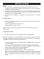
MIRA CODA
THERMOSTATIC SHOWER
VALVE
Installation & User Guide
These instructions are to be left with the user
1
PATENT APPLICATION
GB 2 407 138A
2
SPECIFICATIONS
Notes
1. The installation, commissioning and maintenance must be carried out in
accordance with instructions supplied by the manufacturer, and be installed by
qualified or competent persons.
2. Installations must comply with the requirements of UK Water Regulations/Byelaws (Scotland), Building Regulations or any particular regulations and practices,
specified by the local water supplier.
3. The Mira Coda is supplied and designed to operate with Mira L11 shower
fittings.
Pressure Range
•
•
•
Minimum maintained pressure: 0.2 bar (2.0 metre head) when used with Mira
L11 shower fittings.
Maximum maintained pressure: 5.0 bar.
Maximum static pressure: 10 bar.
Note! Nominally equal inlet supply pressure are recommended for optimum
performance.
Temperature Control
•
Close temperature control is provided between 20°C and 50°C.
Note! The temperature control specification, outlined below, is achieved with the
blend between 35°C and 45°C, with supply temperatures of 15°C cold and 65°C
hot, AND, nominally equal inlet supply pressures.
•
•
•
•
•
The blended temperature is maintained within 2°C with a 10°C change in the
hot or cold supply.
The wax capsule sensor effects a shut down to seepage in approximately
5 seconds if the cold supply fails. Shut down to seepage is only achieved if
the hot supply is 10°C above the blend temperature.
Minimum hot water supply temperature: 55°C
Maximum hot water supply temperature: 90°C for short periods.
BS 6700 recommends that the temperature of stored water should never exceed
65°C. A stored water temperature of 60°C is considered sufficient to meet all
normal requirements and will minimise the deposition of scale in hard water
areas.
3
INSTALLATION
General
1.
The installation, commissioning and maintenance must be carried out according
to instructions supplied, and must be conducted by qualified or competent
person.
2. Before starting installation, ensure that all site requirements correspond to
information given in the SPECIFICATION section.
3. DO NOT install product in a position where it could become frozen.
4. Install in a position with easy access for maintenance.
5. Accessible isolating valves MUST be provided for maintenance.
6. The supply pipework MUST be thoroughly flushed to remove any debris before
connection.
7. The hot water supply must be connected to left inlet (next to the flow selector).
This shower does not allow for reversed inlets.
8. Installations must comply with the requirements of UK Water Regulations/Byelaws (Scotland), Building Regulations or any particular regulations and practices,
specified by the local water supplier.
9. No form of outlet flow control should be fitted. Only use L11 shower fittings
recommended by the manufacturer/supplier.
10. Do not install the shower control in a position that restricts service access. A
minimum distance of 150mm is required between the hot and any side wall.
11. Do not use excessive force when making connection.
12. The supplied wall mounting bracket must be used for stud partition or laminated
panel walls to ensure the valve is fully supported.
4
Solid Wall Installation
For installation onto a stud partition or laminated panel wall, or onto unfixed rearentry pipework, refer to the next section: Stud Partition, Laminated Panel, or
Unfixed Rear-entry Pipework Installation.
1.
1/2" BSP Female
Connector
Make sure that the pipework is set
at the correct distance apart and
solidly fixed as this supports the
valve. Apply suitable thread sealant
(not supplied) and attach the offset
connectors to the pipework in the
wall.
Offset Connector
Pipework
Wall
Spanner Flats
2.
Tighten the offset connectors using
a spanner on the flats. Make sure
that the connectors are level and set
at the correct distance apart when
tightened.
150mm
150mm
Offset Connectors
3.
Screw the concealing plates onto
the offset connectors until they come
into contact with the wall. Seal with
an appropriate sealant.
5
4.
5.
6.
7.
Caution! Ensure supply pipework is
flushed before installing the shower
valve.
Assemble the shower valve with a
sealing washer in each inlet and
attach to the offset connectors.
Tighten the nuts using a suitable
spanner.
Connect the shower fittings to the
shower valve outlet.
Turn on the water supplies and check
for leaks at all pipe connections.
Sealing Washer
Shower Valve
Shower Valve Outlet
Stud Partition, Laminated Panel, or Unfixed Rear-entry Pipework Installation
1.
Screw the mounting bracket onto the
offset connectors.
Offset Connector
Wall Mounting Bracket
Mounting Bracket
2.
The mounting bracket must extend in
the same direction as the offset of the
offset connector. The angle between
the offset connector and the mounting
bracket must be less than 45°.
Otherwise, the mounting bracket will
not fit under the concealing plate.
Offset Connector
45°
45°
Wall
Offset Connector
3.
The mounting bracket boss should
protrude to the rear, facing the wall.
Boss
6
Mounting Bracket
4.
Apply suitable thread sealant (not
supplied) and attach the offset
connectors to the pipework in the
wall. Make sure that the connectors
are level and set at the correct
distance apart.
Mounting Bracket
Offset
Connector
Pipework
Wall
Spanner Flats
5.
6.
7.
Tighten the connection to the pipework
while holding the offset connectors in
place using a spanner on the spanner
flats.
Fix the mounting bracket to the wall
through the small hole, using the
appropriate wall fixings for the type
of wall (not included).
Small Fixing Hole
Screw the concealing plates onto
the offset connectors until they come
into contact with the wall. Seal with
an appropriate sealant.
Concealing Plates
7
Caution! Ensure supply pipework is
flushed before installing the shower
valve.
8. Assemble the shower valve with a
sealing washer in each inlet and
attach to the offset connectors.
9. Tighten the nuts using a suitable
spanner.
10. Connect the shower fittings to the
shower valve outlet.
11. Turn on the water supplies and check
for leaks at all pipe connections.
Sealing Washer
Shower Valve
Shower Valve Outlet
COMMISSIONING
Setting the Maximum Temperature
The Mira Coda Thermostatic Mixer has been preset to approximately 41°C under
ideal conditions at the factory, which is appropriate for most systems. However,
site conditions and personal preference may make it necessary to reset this
temperature.
Caution! Before testing the mixer, ensure that the hot and cold water are
flowing correctly by exercising the temperature selector knob between the cold
and hot stops.
1.
2.
3.
4.
Turn the temperature selector
knob to position 7 and test that
the temperature of the water from
the shower outlet is between 39°C
and 41°C (as measured with a bath
thermometer). If the water is not in
this range of temperatures, proceed
with the following procedure.
Turn the temperature selector knob
to the fully cold position.
Hold down the temperature override
button and slowly turn the knob
until the output water reaches a
temperature of 41°C.
Wait for the water temperature to
stabilise.
Temperature
Selection Knob
Stop Assembly
Override Button
Fixing Screw
Cover Plate
8
5.
Insert a small screwdriver into the
notch and pry off the cover plate.
6.
Unscrew the fixing screw.
7.
Remove the temperature selector
knob without disturbing the stop
assembly.
Fixing Screw
Temperature
Selector Knob
Cover Plate
8.
Replace the temperature selector
knob so that the 7 mark is level with
the shoulder on the stop assembly .
Stop Assembly
(Shoulder)
9.
Replace the fixing screw and the
cover plate.
Stop Assembly
9
OPERATION
Adjusting the Temperature
The temperature is controlled by rotating the temperature selector knob.
For safety reasons, the temperature is limited by a stop. To obtain a higher
temperature, press the override button on the temperature selector knob and
continue to rotate the knob.
Adjusting the Flow
The flow is controlled by rotating the flow selector knob.
Override
Button
Decrease
Temperature
Increase
Temperature
Temperature Selector Button
On/Increase Flow
Flow Selector Knob
Off/Decrease Flow
10
FAULT DIAGNOSIS
Read the section: Important Safety Information first.
Provided that the Mira Coda has been correctly installed and is operated in
accordance with the instructions contained in this guide, difficulties should not
arise. If any maintenance is required then it must be carried out by a competent
tradesperson for whom the fault diagnosis chart and maintenance instructions are
provided. Before replacing any parts make sure that the underlying cause of the
malfunction has been identified.
Symptom
Cause / Rectification
1.
Only hot or cold a.
water from mixer
outlet.
Inlet supplies reversed.
2.
F l u c t u a t i n g o r a.
reduced flow.
b.
Check that the Inlet Filters are not blocked.
Make sure that the minimum flow rate is sufficient for
the supply conditions.
Make sure that the maintained inlet pressures are
nominally balanced and sufficient.
Make sure that the inlet temperature differentials are
sufficient.
Airlock or partial blockage in pipework.
c.
d.
e.
3.
No flow from mixer a.
outlet.
b.
c.
Make sure that the Inlet Isolating Valves are open.
Hot or cold supply failure. Make sure that the hot and
cold supplies are available to the BSM.
Refer to symptom 2.
4.
Blend temperature a.
drift.
b.
c.
d.
e.
Inlet supplies reversed.
Hot supply temperature fluctuation.
Supply pressures fluctuating.
Thermal Cartridge defective.
Inlet Filters Blocked.
5.
Maximum blend a.
temperature
setting too hot or b.
too cold.
Indicates incorrect maximum temperature setting,
refer section: 'Commissioning'.
Refer to symptom 4.
11
Symptom
6.
Cause / Rectification
Drip from handset. A small amount of water may be retained in the fitting
after the shower control has been turned off. This
may drain over a few minutes. This is quite normal.
Changing the angle of the shower fitting may vary the
draining time.
Defective ceramic plates within the shower cartridge.
Renew the cartridge assembly.
12
MAINTENANCE
General
This Product is precision engineered and should give continued safe and
controlled performance, provided:
1. It is installed, commissioned, operated and maintained in accordance with
manufacturers recommendations.
2. Periodic attention is given, when necessary, to maintain the product in good
functional order.
Lubricants
Standard silicone-only based lubricants may be used to assist refitting.
Warning! Use silicone-only based lubricants. Do not use oil-based or other
lubricant types as rapid deterioration of seals may occur.
Cleaning
The Mira Coda should be cleaned using a mild washing up detergent or soap
solution, rinsed and then wiped dry with a soft cloth.
Warning! Many household cleaners contain abrasive and chemical substances,
and should not be used for cleaning plated or plastic fittings.
13
Maintaining the Non-Return Valves
The non-return valves are located in the valve body, and are accessible through
the inlet connectors.
Caution! Ensure that the non-return valves are installed correctly to prevent
crossflow or malfunction of the valve.
1.
2.
3.
With the water supplies turned off
and the thermostatic mixer removed,
remove the washer, the circlip and the
filter.
Remove the non-return valve and
clean any debris.
On reassembly ensure that the nonreturn valve is fitted the correct way
round (with the arrow indicating the
flow pointing towards the mixer).
Flow Arrow
Non-return Valve
Circlip
Filter Washer
Filter
The inlet filters are located in the inlet connector. Clean or renew as necessary.
Thermostatic Cartridge
In hard water areas the filters in the thermostatic cartridge may become blocked
with limescale, which will reduce the flow of water. It is recommended that the cartridges are checked regularly and cleaned in a descaling solution (such as kettle
descalent) if necessary. Be sure to follow the manufacturer’s instructions on the
descalent package.
Note! The cartridge is non-servicable and will require replacement should failure
occur.
14
SPARES
456.29
Wall Mounting
Bracket
1630.045
Temperature Knob
Assembly
1630.041
Offset Connector Kit
1630.043
1630.042
Thermostatic
Non Return Valve Cartridge
1630.049
Filter Washer
1630.044
Temperature Stop
1630.047
Flow Knob Assembly
1630.048
Outlet Connector
1630.046
Flow Cartridge
15
CUSTOMER SERVICE
UKAS
1065367-W2-A
16
© Kohler Mira Limited, August 2006