1
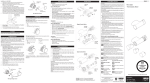
Thermostatic
Bar Valve
Installation and User Guide
These instructions are to be left with the user
1
Contents
Introduction.............................................................................................. 3
Guarantee............................................................................................. 3
Recommended Usage........................................................................... 3
Patents.................................................................................................. 3
Safety : Warnings..................................................................................... 4
Pack Contents.......................................................................................... 5
Dimensions............................................................................................... 5
Specifications........................................................................................... 6
Installation................................................................................................ 7
General.................................................................................................. 7
Solid Wall Installation............................................................................ 8
Stud Partition, Laminated Panel,
or Unfixed Rear-entry Pipework Installation.................................. 9
Assembly of Control Knobs................................................................. 11
Operation................................................................................................ 12
Adjusting the Temperature.................................................................. 12
Adjusting the Flow............................................................................... 12
Commissioning...................................................................................... 13
Setting the Maximum Temperature..................................................... 13
Fault Diagnosis....................................................................................... 14
Maintenance............................................................................................ 15
Type 2 Valves.......................................................................................... 18
Spare Parts............................................................................................. 19
Accessories............................................................................................ 20
Notes....................................................................................................... 21
Customer Service.....................................................................Back Page
2
Introduction
Thank you for purchasing a quality Mira product. To enjoy the full potential of your
new product, please take time to read this guide thoroughly, having done so, keep
it handy for future reference.
The Mira Discovery Thermostatic Bar Valve is a Thermostatic Shower Control
designed for wall mount installations.
The Thermostatic Bar Valve has two knobs, one knob controls the flow and the other
knob controls the temperature.
The Thermostatic Bar Valve incorporates a wax capsule temperature sensing
unit, which provides an almost immediate response to changes in pressures or
temperature of the incoming water supplies to maintain the selected temperature.
An adjustable maximum temperature stop is provided which limits the temperature
to a safe level. Inlet Filters are fitted to protect the thermostatic cartridge.
This product has been certified as a Type 2 valve under the BUILDCERT TMV2
scheme. This product also complies with the Water Supply (water fittings) Regulations
1999.
Guarantee
For domestic installations, Mira Showers guarantee the Mira Discovery Thermostatic
Bar Valve against any defect in materials or workmanship for a period of three years
from the date of purchase (shower fittings for one year).
For non-domestic installations, Mira Showers guarantee the Mira Discovery
Thermostatic Bar Valve against any defect in materials or workmanship for a period
of one year from the date of purchase.
For terms and conditions refer to the back cover of this guide.
Recommended Usage
Application
Valve with Fittings
Domestic
ü
Light Commercial
ü
Heavy Commercial
û
Healthcare
û
Patents
Patents
GB
2 407 138
If you experience any difficulty with the installation or operation of your new
Thermostatic Mixer, please refer to ‘Fault Diagnosis’, before contacting Kohler Mira
Ltd. Our telephone and fax numbers can be found on the back cover of this guide.
3
Safety : Warnings
This Mira Discovery Thermostatic Bar Valve is precision engineered and should give
continued safe and controlled performance, provided:
1. It is installed, commissioned, operated and maintained in accordance with
manufacturers recommendations.
2. Periodic attention is given, when necessary, to maintain the product in good
functional order.
Caution!
1. Read all of these instructions.
2. Retain this guide for later use.
3. Pass on this guide in the event of change of ownership of the installation
site.
4. Follow all warnings, cautions and instructions contained in this guide.
5. Anyone who may have difficulty understanding or operating the controls of any
shower should be attended whilst showering. Particular consideration should
be given to the young, the elderly, the infirm or anyone inexperienced in the
correct operation of the controls.
6. When this product has reached the end of its serviceable life, it should be
disposed of in a safe manner, in accordance with current local authority
recycling, or waste disposal policy.
4
Pack Contents
Tick the appropriate boxes to familiarise yourself with the part names and to
confirm that the parts are included.
1 x Mira Discovery Bar Valve
1 x Flow Knob
1 x Temperature Knob
2 x Concealing Plates
2 x Inlet Seals / Filters
2 x Wall Mounting Brackets
2 x Offset Connectors
Documentation
1 x Guarantee Brochure
Dimensions
150 mm ± 15 mm
80 mm
107 mm
1/2” BSP
Ø 70 mm
287 mm
5
1/2” BSP
Specifications
For Type 2 Valves, the supply conditions specified in section: ‘Type 2 Valves Application’ take precedence over the operating parameters which follow.
Pressure Range
• Minimum maintained pressure: 0.2 bar (2.0 metre head).
•
•
Maximum maintained pressure: 5.0 bar.
Maximum static pressure: 10 bar.
Note! Nominally equal inlet supply pressure are recommended for optimum
performance.
Temperature Control
• Close temperature control is provided between 20°C and 50°C.
•
•
•
•
•
Note! The temperature control specification, outlined below, is achieved with
the blend between 35°C and 45°C, and supply temperatures of 15°C cold and
65°C hot, AND, nominally equal inlet supply pressures.
The blended temperature is maintained within 2°C with a 10°C change in
the hot or cold supply.
The wax capsule sensor effects a shut down to seepage in approximately
2 seconds if the cold supply fails. Shut down to seepage is only achieved if
the hot supply is 10°C above the blend temperature.
Minimum hot water supply temperature: 55°C
Maximum hot water supply temperature: 90°C for short periods.
BS 6700 recommends that the temperature of stored water should never
exceed 65°C. A stored water temperature of 60°C is considered sufficient
to meet all normal requirements and will minimise the deposition of scale in
hard water areas.
Connections
Connections are:
• Hot - Left (side nearest flow control), ½" BSP Male.
•
•
Cold - Right (side nearest temperature control), ½" BSP Male.
Bottom-Outlet, ½" BSP Male.
Note! This product does not allow for reversed inlets.
Offset connector (inlet centres are 150 mm ± 24 mm):
¾" BSP
Connection to Bar Valve
½" BSP
Connection to Pipework
6
Installation
General
The Control Knobs will require fitting prior to use refer to section: ‘Assembly of
Control Knobs’ for instruction.
Installation must be carried out in accordance with these instructions, and must be
conducted by designated, qualified and competent personnel.
The installation must comply with the “Water Supply Regulations 1999 (Water Fittings)”
or any particular regulations and practices, specified by the local water company or
water undertakers.
Note! Make sure that all site requirements correspond to the information given in
section: ‘Specifications’. For Type 2 Valves see also supply conditions in section:
‘Type 2 Valves’.
1. The Bar Valve must not be installed in an area where it may freeze.
2. For stud partitions alternative fixings may be required.
3. Isolating valves must be installed close to the Bar Valve for ease of
maintenance.
4. Pipework must be rigidly supported and avoid any strain on the connections.
5. Pipework dead-legs should be kept to a minimum.
6. Supply pipework layout should be arranged to minimise the effect of other outlet
usage upon the dynamic pressures at the Mixer inlets.
7. Inlet and outlet threaded joint connections should be made with PTFE tape or
liquid sealant. Do not use oil-based, non-setting joint compounds.
8. To eliminate pipe debris it is essential that supply pipes are thoroughly flushed
through before final connection.
9. Decide on a suitable position for the
Bar Valve. The position of the Bar
Valve and the Shower Fittings must
provide a minimum gap of 25 mm
between the spill-over level of the
Hose Retaining Ring
shower tray/bath and the handset.
This is to prevent back-siphonage. For
further information on the installation
of your Shower Fittings, refer to the
Fittings Installation and User Guide.
Note! Only use Shower Fittings
recommended by the manufacturer
or supplier.
25 mm
Spill Over
Level
7
Solid Wall Installation
For Solid Wall installations the Thermostatic Bar Valve can be supported by the
pipework provided that it is securely fixed to the wall. Alternatively for unfixed rear
entry pipework the Wall Mounting Bracket can be used.
For installation onto a Stud Partition, Laminated Panel, or onto Unfixed Rear‑entry
Pipework (using the Wall Mounting Bracket) refer to section: 'Stud Partition,
Laminated Panel, or Unfixed Rear-entry Pipework Installation'.
1.
Install the pipework, make sure that
it is set at the correct distance apart
(150 ± 24 mm) and solidly fixed as
this supports the valve.
150 ± 24 mm
Pipe Centres in Wall
½" BSP Female
Connection
Offset
Connector
Ø 22 mm
Tile
2.
3.
Apply suitable thread sealant (not
supplied) and attach the Offset
Connectors to the pipework in the
wall.
Note! Connections are: Hot-Left,
Cold-Right, Bottom-Outlet.
Tighten the Offset Connectors using
a spanner on the spanner flats. Make
sure that the Connectors are level
and set at the correct distance apart,
using the Bar Valve as a guide to
spacing.
4.
Screw the Concealing Plates onto the
Offset Connectors until they come
into contact with the wall.
5.
Install the Bar Valve, refer to section:
‘Stud Partition, Laminated Panel,
or Unfixed Rear-entry Pipework
Installation’ and follow instructions
9 to 12.
8
Support
Bracket
Pipework
Wall
Apply Silicone
Sealant
Spirit Level
150 mm
Spanner Flats
Concealing Plates
Wall Mounting Bracket
(Alternative Fixing Method)
Stud Partition, Laminated Panel, or Unfixed Rear-entry
Pipework Installation
For all installations using the Wall Mounting Bracket:
1.
2.
3.
150 ± 24 mm
Install the pipework, make sure that
Pipe Centres in Wall
it is set at the correct distance apart
(150 ± 24 mm) and solidly fixed.
Screw the Mounting Brackets onto
the Offset Connectors to the depth
Ø 27 mm
shown in the illustration.
The Mounting Bracket must extend in the same direction as the offset of the
Offset Connector. The angle between the Offset Connector and the Mounting
Bracket must be less than 45°, otherwise the Mounting Bracket will not fit under
the Concealing Plate.
Offset
Connector
35 - 40 mm
45°
Wall Mounting
Bracket
4.
5.
45°
The Mounting Bracket Boss should protrude to the rear, facing the wall.
Apply suitable thread sealant (not supplied) and attach the Offset Connectors
to the pipework in the wall.
Note! Connections are: Hot-Left, Cold-Right, Bottom-Outlet.
10 mm
½" BSP Female
Connection
Wall
Offset
Connector
Boss
Wall Mounting
Bracket
Apply Silicone
Sealant
Support
Bracket
Pipework
9
Spirit Level
150 mm
6.
7.
8.
Tighten the Offset Connectors using a spanner on the spanner flats. Make sure
that the Connectors are level and set at the correct distance apart, using the
Bar Valve as a guide to spacing.
Fix the Mounting Bracket to the wall through the small hole, using the appropriate
wall fixings for the type of wall (not supplied).
Caution! Take care not to drill though any concealed pipework.
Screw the Concealing Plates onto the Offset Connectors until they come into
contact with the wall.
Spanner Flats
35 - 40 mm
Concealing Plates
9.
Caution! Make sure that the supply
pipework is flushed before installing
the Bar Valve.
Assemble the Bar Valve with a Sealing
Washer / Filter in each inlet and
attach to the Offset Connectors.
10. Tighten the connection using a
20 mm spanner.
11. Install the Shower Fittings, refer to
the Shower Fittings Installation and
User Guide.
12. Turn on the water supplies and check
for leaks at all pipe connections.
Sealing
Washer / Filter
Bar Valve
Outlet
10
Assembly of Control Knobs
Flow Knob
1.
2.
Rotate the Flow Hub fully clockwise.
Both the Bar Valve and the Flow Knob have a flow stop marking, align both of
the marks and push the Flow Knob until it locks onto the flow hub.
Flow Hub
Flow Knob
Align Flow
Stop Marks
Temperature Knob
1.
2.
3.
Rotate the Temperature Hub fully anti-clockwise.
Hold the Bar Valve with the Outlet facing down then align the red temperature
marking on the Temperature Knob toward the Bar Valve as illustrated.
Push the Temperature Knob onto the Bar Valve until it locks onto the Temperature
Hub.
Temperature
Marking (red)
Temperature Hub
Temperature
Knob
Outlet
Connector
11
Operation
Adjusting the Temperature
The temperature is controlled by rotating the temperature control knob on the right
side of the shower.
Adjusting the Flow
The flow is controlled by rotating the flow control knob on the left side of the
shower.
Increase
Temperature
Off/Decrease
Flow
Decrease
Temperature
Temperature
Control Knob
On/Increase
Flow
Flow Control
Knob
12
Commissioning
Setting the Maximum Temperature
The Mira Discovery Thermostatic Bar Valve has been preset to a safe showering
temperature under ideal conditions at the factory, appropriate for most systems.
However, site conditions and personal preference may make it necessary to reset
this temperature.
Caution! Before testing the mixer, make sure that the hot and cold water are
flowing correctly by turning the temperature selector knob between the cold and
hot stops.
For Type 2 installations the maximum blend temperature is determined by the
application, refer to section: ‘Type 2 Valves - Application’.
1. Turn on the shower.
2. Turn the temperature selector knob to full hot and test the temperature of the
water from the shower outlet. If the water is not at the required temperature,
proceed with the following procedure.
3. Turn off the shower.
4. Carefully pull off the temperature control knob.
Note! Force will be required to pull the temperature control knob from the
shower.
5. Unscrew the hub retaining screw.
6. Remove the temperature hub and replace it one spline clockwise to increase
the temperature.
Note! One spline clockwise equals approximately, 2°C increase in
temperature.
7. Tighten the hub retaining screw.
8. Install the temperature knob. Make sure that the stop feature inside the knob
is towards the top.
9. Turn on the shower and check the maximum temperature setting. If further
adjustment is required repeat the above procedure.
Hub Retaining
Screw
Splines
Temperature Hub
13
Temperature
Control Knob
Fault Diagnosis
Symptom
Cause / Rectification
1.
Only hot or cold a.
water from mixer b.
outlet.
c.
Inlet supplies reversed / change pipework.
Faulty Non-Return Valve.
Check that the Inlet Filters are not blocked.
2.
F l u c t u a t i n g o r a.
reduced flow.
b.
Check that the Inlet Filters are not blocked.
Make sure that the minimum flow rate is sufficient
for the supply conditions.
Make sure that the maintained inlet pressures are
nominally balanced and sufficient.
Make sure that the inlet temperature differentials are
sufficient.
Airlock or partial blockage in pipework.
c.
d.
e.
3.
N o f l o w f r o m a.
mixer outlet.
b.
c.
Make sure that the Inlet Isolating Valves are open.
Hot or cold supply failure. Make sure that hot and
cold supplies are available.
Refer to symptom 2.
4.
Blend temperature a.
drift.
b.
c.
d.
e.
Inlet supplies reversed.
Hot supply temperature fluctuation.
Supply pressures fluctuating.
Thermal Cartridge defective.
Inlet Filters Blocked.
5.
Maximum blend a.
temperature
setting too hot or b.
too cold.
Indicates incorrect maximum temperature setting,
refer section: 'Commissioning'.
Refer to symptom 4.
6.
Drip
f r o m a.
handset.
A small amount of water may be retained in the fitting
after the shower control has been turned off. This
may drain over a few minutes. This is quite normal.
Changing the angle of the shower fitting may vary
the draining time.
Defective ceramic plates within the shower
cartridge.
Renew the cartridge assembly.
b.
c.
14
Maintenance
General
This Product is precision engineered and should give continued safe and controlled
performance, provided:
1. It is installed, commissioned, operated and maintained in accordance with
manufacturers recommendations.
2. Periodic attention is given, when necessary, to maintain the product in good
functional order.
If you require a Mira trained engineer or agent, refer to section: ‘Customer
service’.
Lubricants
Silicone based lubricants must only be used on the rubber seals.
Caution! Oil based or other lubricant types may cause rapid deterioration of
seals.
Cleaning
The chrome plated parts should be cleaned using a mild washing up detergent or
soap solution, rinsed and then wiped dry with a soft cloth.
Warning! Many household cleaners contain abrasive and chemical substances,
and should not be used for cleaning plated or plastic fittings.
Do not use descalents on this product.
In-service Tests
The principal means for determining the continuing satisfactory performance of the
mixing valve is the in-service test.
Follow the procedure detailed in the flow diagram “In-service Test Procedure”.
Frequency of In-service Tests
Commercial (non-domestic installations)
Check for correct blend setting every 6 months.
Follow the procedure detailed in the flow diagram “In-service Test Procedure”, every
12 months.
15
Start
Measure and record supply
temperatures and pressures. Make sure
that they are within Valve specifications.
Measure and record blend
temperature(Tb) and flow rate.
Has flow rate fallen
significantly or fallen
below minimum flow
specification?
Yes
Check and clean checkvalves,
strainers and outlet.
Measure and record blend
temperature(Tb) and flow rate.
No
Yes
Carry out a performance check. Refer
to the commissioning procedure.
Has the blend
temperature changed
by more than 2°C from
previous recorded
value(Tb)?
Has flow rate
improved?
No
Yes
No
Refer to section: ‘Fault
Diagnosis’.
Finish
Carry out the commissioning
procedure.
Note! All measurements and results should be recorded in the Log Book.
Flow Diagram, In-service Test Procedure
16
Maintaining the Non-Return Valves
The Non-Return Valves are located in the Bar Valve Body, and are accessible through
the Inlet Connectors.
Caution! Make sure that the Non-Return Valves are installed correctly to prevent
crossflow or malfunction of the Valve.
1.
2.
3.
With the water supplies turned off and
the Thermostatic Bar Valve removed,
remove the Washer / Filter, and the
Circlip
Carefully remove the Non-Return
Valve and clean any debris.
On re assembly make sure that the
Non-Return Valve is fitted the correct
way round (with the arrow indicating
the flow pointing towards the Valve).
Flow Arrow
Circlip
Non-return Valve
Washer / Filter
Filters
The Inlet Washers / Filters are located in the Inlet Connector. Clean or renew as
necessary.
Thermostatic Cartridge
In hard water areas the Filters in the Thermostatic Cartridge may become blocked
with limescale, which will reduce the flow of water. It is recommended that the
Cartridges are checked regularly and cleaned in a descaling solution (such as kettle
descalent) if necessary. Be sure to follow the manufacturer’s instructions on the
descalent package.
Note! The Thermostatic Cartridge is non-servicable and will require replacement
should failure occur.
17
Type 2 Valves
Application
The approved designations for Type 2 Valves are as follows:
Model
Designation
Mira Discovery Bar Valve
HP-S
The permitted application details are:
Designation
Operating
Pressure Range
Application
Mixed Water
Temperature†°C
HP-S
Low Pressure
Shower
41°C Maximum
Mixed water temperature at discharge point.
Important! For TMV2 installations the mixed water temperature at the discharge
point should never exceed 46°C.
In order to achieve the safe water temperatures expected of a Type 2 Valve it is
essential that the valve is used only for the applications covered by its approved
designations, with the appropriate water supply pressures and temperatures, and it
is commissioned, maintained and serviced in accordance with the recommendations
contained in this guide (refer to the section ‘Maintenance, In-Service Tests’
for in service test frequency that must be used as a minimum guide in Type 2
installations).
†
Supply Conditions
For applications where a Type 2 Valve is required, the supply conditions must comply
with the values in the Table below. Note that both hot and cold supply pressures
must lie within the same pressure range.
Operating Pressure
Range
High Pressure
Low Pressure
Maximum Static
Pressure (bar)
10
10
Maintained Pressure,
Hot and Cold (bar)
1 to 5
0.2 to 1
Hot Supply
Temperature (°C)
55 to 65
55 to 65
Cold Supply
≤ 25
≤ 25
Temperature (°C)
Valves operating outside these conditions cannot be guaranteed to operate as
Type 2 Valves.
18
Spare Parts
456.22
Non Return Valve Assembly
456.28Outlet Connector
456.29
Wall Mounting Bracket
467.01
Thermostatic Cartridge Assembly
467.04
Flow Cartridge Assembly
1609.030 Offset Connector Kit
1609.031 Temperature Knob
1609.032 Flow Knob
1609.031
1609.030
456.22
456.29
467.01
456.28
467.04
1609.032
19
ACCessorIes
Genuine Mira accessories can be purchased direct from Customers Services (our contact details can
be found on the back cover of this guide) or from approved stockists or merchants.
eco showerhead
White - 2.1668.001
Chrome - 2.1668.002
The Eco shower head gives
you an invigorating shower, but
reduces water consumption and
heating costs.
everclear showerhead
White - 2.1616.030
Chrome - 2.1616.031
Mira's new Everclear range has
been specially designed for hard
water areas and reduces the risk
of lime scale build up.
showerhead Holder
White - 1.1540.270
Chrome - 1.1540.271
An alternative to the traditional
slide bar. Often a useful addition
when positioned for the smaller
members of the family.
Wall Mounted soap Dish
White - 1.1540.278
Chrome - 1.1540.279
Wall mounted for use anywhere
in, or outside the showering
area.
shower seat
White - 2.1536.128
White/Chrome - 2.1536.129
For use in or out of the
showering area. note! must be
installed onto a solid wall.
Shower seat folds up when not
in use
Double outlet Check Valve
(DCV-H)
Chrome - 1.0.110.55.1
DCV-H: An outlet double check
valve, designed to prevent the
backflow or backsiphonage of
potentially contaminated water,
through shower controls which
are fitted with a flexible hose as
part of the outlet shower fitting.
20
1
notes
21
notes
22
notes
23
Customer Service
Guarantee
Your product has the benefit of our manufacturer’s
guarantee which starts from the date of purchase.
To activate this guarantee, please return your completed
registration card, visit our website or free phone 0800
0731248 within 30 days of purchase (UK only).
Within the guarantee period we will resolve defects in
materials or workmanship, free of charge, by repairing or
replacing parts or product as we may choose.
This guarantee is in addition to your statutory rights
and is subject to the following conditions:
● The product must be installed and maintained in
accordance with the instructions given in this user
guide.
● Servicing must only be undertaken by us or our
appointed representative. note! if a service visit
is required the product must be fully installed and
connected to services.
● Repair under this guarantee does not extend the original
expiry date. The guarantee on any replacement parts
or product ends at the original expiry date.
● For shower fittings or consumable items we reserve
the right to supply replacement parts only.
The guarantee does not cover:
● Call out charges for non product faults (such as
damage or performance issues arising from incorrect
installation, improper use, lack of maintenance, build up
of limescale, frost damage, corrosion, system debris or
blocked filters) or where no fault has been found with
the product.
● Water or electrical supply, waste and isolation issues.
● Compensation for loss of use of the product or
consequential loss of any kind.
● Damage or defects caused if the product is repaired
or modified by persons not authorised by us or our
appointed representative.
● Routine maintenance or replacement parts to comply
with the requirements of the TMV 2 or TMV 3 healthcare
schemes.
Helpdesk service
Our dedicated Customer Services Team is comprehensively
trained and can offer help and advice, spare parts,
accessories or a service visit. We will need you to have your
model name or number, power rating (if applicable) and date
of purchase. As part of our quality and training programme
calls may be recorded or monitored.
Mira showers Website (www.mirashowers.co.uk)
From our website you can register your guarantee,
download additional user guides, diagnose faults, purchase
our full range of accessories and popular spares, refer to
our FAQ’s and request a service visit.
spares and Accessories
We maintain extensive stocks of genuine spares and
accessories and aim to provide support throughout the
product’s expected life. Payment can be made by phone
at time of order using most major Credit or Debit cards and
we aim to despatch orders within two working days. Items
purchased from us are guaranteed for 12 months from date
of purchase. For safety reasons spares exposed to mains
voltages should only be fitted by competent persons.
returns – items can be returned within one month of date of
purchase, providing that they are in good condition and the
packaging is unopened. Please obtain authorisation from
our Customer Services Team before return. We reserve the
right to apply a 15% restocking charge.
service / repairs
We have a nationwide team of Service Technicians who can
carry out all service or repair work to your product within the
guarantee period and beyond. You have the assurance of a
fully trained Mira Technician, genuine Mira spare parts and
a 12 month guarantee on any chargeable work done.
Payment should be made directly to the Service Technician
who will accept most major Credit or Debit cards.
To Contact us
uk
Telephone: 0844 571 5000
Mon to Fri 8:00 am - 5:30 pm, Sat 8:30 am - 3:30 pm
E-mail: [email protected]
If your product does not function correctly when you first Fax: 01242 282595
use it, contact your installer to check that it is installed By Post: Mira Customer Services Dept, Cromwell Road,
and commissioned in accordance with the instructions in cheltenham, Gloucestershire, Gl52 5eP
this manual.
Should this not resolve the issue, contact our Customer eire
Services Team who will offer you or your installer advice and Telephone: 01 459 1344
if applicable arrange for a Service Technician to call.
Mon to Fri 9:00 am - 5:00 pm
If the performance of your product declines, check in this E-mail: [email protected]
manual to see if simple home maintenance is required. If Fax: Dublin 01 459 2329
you require further assistance call our Customer Services
By Post: Modern Plant Ltd (Dublin),
Team.
Otter House, Naas Road, Clondalkin, Dublin 22
What to do if something goes wrong
ExtendedGuarantees
A selection of protection plans are available that
enable you to cover repair bills for the life of your policy
(excludes Eire). Ring 01922 471763 for more details.
Mira is a registered trade mark of
Kohler Mira Limited.
The company reserves the right to alter
product specifications without notice.
1054969-W2-C (B92B) (1609)
UKAS
24
© Kohler Mira Limited, July 2009