1
REMOTE CONTROL
ENGINE STARTER
INSTALLATION MANUAL
XRT - BBK - BBF - BBU - BBW
CONTROL MODULES
FOR ALL
GAS, DIESEL
AND HYBRID
POWERED VEHICLES
THIS PRODUCT MUST BE INSTALLED
BY A QUALIFIED INSTALLER.
When this product is installed in a manual transmission vehicle,
the installation must be done with a manual interface
(not included - No. RS-MI).
(Instructions en français au verso)
PATENT NUMBERS
CAN 1.130.426
USA: 4.345.554 - 5.614.883
5.617.819 - 5.673.017
AND OTHER PATENTS PENDING
All rights reserved
© Astroflex Electronics 2007
August 2007
IBRSS5224
IMPORTANT NOTICE
TO INSTALLERS!
The control module included in this kit must be interfaced according to the
type of vehicle in which it is installed. The control module won’t, IN ANY
WAY, monitor the position of the gearshift lever during a remote start.
It is factory set to "Manual Transmission" mode.
See Stage 1 - Level 16 on page 22 for programming options.
•
For vehicles equipped with a MANUAL TRANSMISSION you must pay
special attention to the instructions identified with the following
pictogram and follow the corresponding instructions.
•
When this product is installed in a manual transmission vehicle,
the installation must be done safely using a manual interface
(not included – part no. RS-MI). This module is designed to force the user to ensure
that the gearshift lever is in neutral and that the parking brake is activated for the
system to proceed to ready mode for remote start.
•
Make sure you deliver the User Manual to the customer
•
Make sure you post the two warning labels in the appropriate locations:
the smaller one must be visible in the driver's side window;
the other must be placed near the hood release lever.
•
•
Make sure you hang the "For your safety" card on the rear-view mirror.
Also make sure all verifications and testing (for automatic or manual transmission
vehicle) is done before and after the installation is done.
Table of contents
VERIFICATIONS AND TESTING TO BE DONE BEFORE THE INSTALLATION........................................................ 2
QUICK GUIDE FOR SKILLED INSTALLERS ................................................................................................................ 3
IMPORTANT NOTE TO BE READ AT THE INSTALLATION ..............................................................................................................................8
CONTROL MODULE PROGRAMMING .......................................................................................................................................................8
DETAILED FEATURES................................................................................................................................................... 9
P1: ALARM (OPTIONNAL) ....................................................................................................................................................................9
P1-1: RED/WHITE: SIREN OUTPUT (+)....................................................................................................................................9
P1-2: GREY: TRUNK OUTPUT (-) .............................................................................................................................................9
P1-3: BLUE: DOME LIGHT OUTPUT (-) ....................................................................................................................................9
P1-5: PINK: ARMED OUTPUT (-) ..............................................................................................................................................9
P1-6: WHITE: DOORS / HORN (-) & P1-7: PURPLE: DOORS / HORN (+) ...............................................................................9
P1-8: YELLOW: ANTI-LOCKING .............................................................................................................................................10
P2: INPUT/OUTPUT ...........................................................................................................................................................................10
P2-1 & 2: RED..........................................................................................................................................................................10
P2-3: BLACK/RED: HOOD INPUT ..........................................................................................................................................10
P2-4: WHITE/GREEN: POSITIVE BRAKE SWITCH INPUT....................................................................................................10
P2-5: ORANGE/WHITE: PARKING LIGHT / GLOW PLUG DETECTION INPUT (±) ..............................................................10
P2-6: DARK GREEN: NEGATIVE OUT WHEN RUNNING .....................................................................................................11
P2-7: ORANGE: ANTI-THEFT OUTPUT.................................................................................................................................11
P2-8: LIGHT GREEN: HORN OUTPUT ..................................................................................................................................11
P2-9: RED/WHITE: +12V OUTPUT..........................................................................................................................................11
P2-10: BLACK/GREEN: TACHOMETER INPUT.....................................................................................................................11
P2-11: BLACK: GROUND INPUT ...........................................................................................................................................11
P2-13 TO P2-16: PROGRAMMABLE OUTPUT #1 TO #4 .......................................................................................................12
P3: POWER DOOR LOCKS .................................................................................................................................................................12
P4: MAIN HARNESS ..........................................................................................................................................................................12
P4-1: RED/BLACK: POWER INPUT .......................................................................................................................................12
P4-2: YELLOW: ACCESSORY OUTPUT................................................................................................................................12
P4-3: GREEN: PARKING LIGHT OUTPUT.............................................................................................................................13
P4-4: ORANGE: IGNITION OUTPUT......................................................................................................................................13
P4-5: DARK BLUE: STARTER OUTPUT ................................................................................................................................13
P4-6: LIGHT BLUE: STARTER CUT INPUT ...........................................................................................................................13
P4-7: RED: POWER INPUT....................................................................................................................................................13
P5: PROGRAMMABLE RELAY .............................................................................................................................................................13
P6 - P16: CONNECTORS FOR PLUG-IN ACCESSORIES ...........................................................................................................................14
P6: SHOCK SENSOR (SUPPLIED WITH ALARM KIT 310-120-503) ......................................................................................14
P7: OTHER SENSOR (SUPPLIED WITH ALARM KIT 310-120-503).......................................................................................14
P9: LED (STATUS) ..................................................................................................................................................................14
P10: TIMER CONTROL ...........................................................................................................................................................14
P11: VALET SWITCH ..............................................................................................................................................................15
P12: MANUAL INTERFACE.....................................................................................................................................................15
P13: MAIN SWITCH.................................................................................................................................................................15
P15: RECEIVER CONNECTOR...............................................................................................................................................15
P16: IM – OM – IOM ACCESSORIES CONNECTOR..............................................................................................................15
DETAILED PROGRAMMING OF THE CONTROL MODULE...................................................................................... 16
PROGRAMMING PROCEDURE ..............................................................................................................................................................16
STAGES PROGRAMMING......................................................................................................................................................16
LEVELS PROGRAMMING.......................................................................................................................................................16
PROGRAMMING TABLES ....................................................................................................................................................................17
DIAGNOSTIC CODES................................................................................................................................................... 24
VERIFICATION OF INSTALLATION ............................................................................................................................ 25
POST-INSTALLATION AND SECURITY TESTS......................................................................................................... 26
CODE LEARNING OF TRANSMITTER (S).................................................................................................................. 27
WITH THE DIP SWITCHES ...................................................................................................................................................................27
WITH THE IGNITION KEY .....................................................................................................................................................................27
1
VERIFICATIONS AND TESTING TO BE DONE
BEFORE THE INSTALLATION
To ensure that the installation and the use of this product are safe,
you must follow the instructions in this manual.
Please pay special attention to the following points.
AUTOMATIC TRANSMISSION VEHICLE
•
Ensure that the vehicle cannot be remote started when in gear. Also ensure that the gearshift
lever cannot be moved out of the "Park" position without first applying the brakes.
If it is possible to crank the engine while the gearshift lever is in gear, or if you can
move the gearshift lever out of "Park" position without pressing on the brakes,
contact our Technical Assistance Department at 1-800-461-8223. A technical
advisor will help you with an appropriate and safe solution based on the make and
model of the vehicle on which you are working.
•
Once the installation is completed, you must check ALL safety devices described in the "POSTINSTALLATION AND SECURITY TESTS" on page 26 of this guide.
MANUAL TRANSMISSION VEHICLE
•
Make sure you have in hand a “manual interface module” part no. RS-MI (not included)
specially made to safely install the remote starter in a manual transmission vehicle.
•
Make sure that all door pin switches work and that the parking brake is operational (i.e. it can
immobilize the vehicle). These security features must be operational before the installation of the
remote starter.
•
Make sure it is impossible to access the gearshift lever without opening a door or the
hatchback.
If the gearshift lever can be accessed without opening a door (i.e. convertibles) or if
opening any one door does not break the safety sequence, we strongly
recommend adding a motion detector (microwave) to prevent a start if any activity
is detected near the gearshift lever. See details on the manual interface
instructions.
•
Once the installation is completed, you must check ALL safety devices described in the
"POST-INSTALLATION AND SECURITY TESTS" on page 26 of this guide. Make sure the
opening of each door and/or of the hatchback (one at a time) breaks the safety sequence that
normally allows the system to initiate a remote start sequence.
2
Quick Guide for Skilled Installers
This section of the installation manual is intended for experienced installers of remote starter and
mobile security products. Only the most frequently needed information are included in the following few
pages. It has been laid out to quickly access connection and operational details to maximize your
installation performance.
If, for any reason, additional information is required on a specific wire, refer to the “Detailed Description”
section on page 9.
Note concerning vehicles equipped with an immobilization system
When the remote starter is installed on a vehicle equipped with a transponder type immobilization
system, it is preferable to complete the installation of the control module and to test it before
proceeding with the connection of the interface that neutralizes the vehicle's immobilization system
(Starter Kill). See details in “Step 2: Full Start Test” on page 25
Each wire that provides a (-)
output can supply only one
single standard Bosch
style automotive relay.
DESCRIPTION OF CONNECTORS
P1 - Alarm Inputs/Outputs (optional)
P2 - Start Inputs/Outputs
P3 - Locking/Unlocking relays
P4 - Power Inputs/Outputs
P5 - Programmable function relay
P6 - Shock sensor
P7 - Other sensor
P9 - LED (Status) - Alarm, Antitheft and
Security sequence status LED
P10 - Programmable timer
P11 - Valet switch
P12 - Manual Interface
P13 - Main switch
P15 - Receiver
P16 - IM / OM Interfaces
FUTURE UTILITY
USAGE FUTURE
FUTURE USE
USAGE FUTUR
Please note,
Yellow - accessory (YEL) and
Green – Parking Light (GRN) wire
can be program for different usage.
(See Stage 2 - Level 1 & 2
of the programming section)
3
DESCRIPTION OF CONNECTORS
The following charts show the purpose of each wire on each connector and list the pin position, color code and give
a brief description of each.
Whenever you need further explanations on a wire or need to access the virtually unlimited programming flexibility of
this AstroStart product, a reference to the detailed installation instructions found later in the manual will allow you to
understand all of the connection and programming options available.
The last chart lists the connectors for the plug-in accessories.
P1 CONNECTOR (Optional)
PIN
COLOR
DESCRIPTION
1
Red/White
Siren Output
(+) 3amp max
Connect this wire to the Red wire of the Siren.
See details on page 9.
2
Grey
Trunk Output
(-) 150ma max
Connect this wire to the circuit that feeds the trunk release mechanism.
See details on page 9.
3
Blue
Dome light
Output
(-) 150ma max
Connect this wire to the circuit that feeds light in passenger compartment.
See details on page 9.
The programming options for this wire are at Stage 1 – Level 4 on page 18 and at
Stage 2 – Level 3 on page 23.
4
-
-
5
Pink
Ground when
armed Output
(-) 150ma max
6
White
Door Input (-)
7
Purple
Door Input (+)
Yellow
Key detection
Input (-)
Connected to “key reminder” circuit on steering column, this input prevents locking
of the doors during automatic rearming of the alarm if key is in the ignition. Only
required if semi-passive or passive arming is selected at Stage 1 - Level 14 or when
“Rearming OEM security system” is enabled in Stage 1 - Level 4.
See details on page 10.
COLOR
DESCRIPTION
PURPOSE
Red
-
3
Black/
Red
Hood pin input
N.O. or N.C.
4
White/
Green
Brake Input
(+)
8
PURPOSE
No connection.
Connect this wire to any device that needs to be neutralized or activated in
conjunction with the integrated alarm system.
See details on page 9.
Connect the White wire to the Negative side and the Purple wire to the Positive side
of the dome light or any light of passenger compartment. These wires are used to
monitor intrusion through the doors.
In Alarm Link mode, they are used to monitor the horn chirps from the OEM alarm.
Both (-) and (+) connections are required.
See details on page 9.
P2 CONNECTOR
PIN
1-2
Parking Light
supervision
Input (±)
5
Orange/
White
Glow Plug
supervision
Input (±)
4
Not use - Do not tap in or cut!
Connect this wire to the provided hood switch.
Default setting: Normally closed when hood is opened.
See Stage 1 – Level 3 on page 18 for programming options.
See page 10 for more details on the input.
SAFETY CIRCUIT - must be connected!
Connect this wire to the brake light circuit of the vehicle.
SAFETY CIRCUIT - must be connected!
See page 10 for more details on the input.
If hookup for Parking light supervision, connect this wire to the Parking Light
circuit of the vehicle. That will allow the remote starter to detect the lights staying ON
when the vehicle is parked.
If hookup for Glow Plug supervision, connect this wire to the circuit that changes
polarity when the Glow Plugs are warm enough to start. This allows remote start to
remain in stand-by mode until Glow plug has preheated (up to 30 sec.).
Default setting: Parking Light supervision, Positive (+)
The programming options for this wire are at Stage 1 – Level 3 on page 18.
See page 10 for more details on the input.
P2 CONNECTOR
PIN
COLOR
DESCRIPTION
PURPOSE
Connect this wire to a circuit that requires a ground during runtime.
Usually a transponder bypass interface.
See page 11 for more details about this output.
6
Dark Green
Ground when running
Output (-) 150ma max
7
Orange
Anti-theft Output
(-) 150ma max
8
Light Green
Horn Output
(-) 150ma max
Connect this wire to factory horn (-) circuit.
See page 11 for more details about this output.
Programming options are at Level 10 & 11 of the Stage 1, starting on page 20
and also at Stage 2 – Level 3 on page 23.
9
Red/
White
+12Volts Output
(+) 1amp max
Connect this wire to the positive side (coil) of additional relays.
Do NOT use for 2nd Ignition or 2nd Starter applications
See page 11 for more details about this output.
10
Black/
Green
Tachometer input
Connect this wire to a circuit in vehicle that provides a pulsed signal
(tachometer signal/RPM)
Default setting: 1 cyl. 800RPM.
See page 11 for more details about this Input.
Programming options are at Stage 1 – Level 2 on page 17.
11
Black
Ground Input
Main Ground.
MUST be connected to left kick panel or firewall only.
13
Brown
14
White/
Blue
15
White
16
Purple
(-) 150ma max for each outputs
N/C - Not used
Programmable Output
12
Connect this wire to an external starter-cut device or an extra anti-theft
status LED.
See page 11 for more details about this output.
Programming options are at Stage 1 – Level 4 on page 18.
#1
#2
#3
#4
Programmable outputs (-) used to control relays or low current circuit.
Programming options are in Level 5 (#1), Level 6 (#2), Level 7 (#3) and in Level
8 (#4) of the Stage 1, starting on page 19. A wiring example is shown page 12.
Programmable outputs default setting:
Output no 1: Pulse Before Start (Disarm)
Output no 2: Pulse After Shutdown (Rearm)
Output no 3: Trunk Release.
Output no 4: Dome Light.
Note concerning connector P16
When an AstroStart interface is connected into P16, verify if it requires the
programming of either one of the programmable outputs 1 & 2. If so,
consider using programmable outputs 3 & 4 instead (P2-15 & P2-16).
P3 CONNECTOR
PIN
COLOR
DESCRIPTION
1
Brown
LOCK Common - 30
2
White/Brown
LOCK N.C. - 87A
3
Brown/White
LOCK N.O. - 87
4
Blue
UNLOCK Common - 30
5
White/Blue
UNLOCK N.C. - 87A
6
Blue/White
UNLOCK N.O. - 87
BUILT-IN RELAY DESCRIPTION
Contacts
85 and 86 are polarized
through the module internal
circuits.
Each relay is controlled by the
function "Locking" or
"Unlocking".
REMARKS: Connector P3 provides access to two on-board Bosch type relays to interface all types of power door
lock circuits. Refer to the AstroChart CD for door lock diagrams.
5
P4 CONNECTOR
PIN
COLOR
DESCRPTION
PURPOSE
1
Red/Black
Power Input
+12V power input, protected by a 30A fuse (F1)
Supplies "Accessory-Yellow Wire" and the "Starter-Dark Blue Wire".
2
Yellow
Accessory
Output (+)
Feeds vehicle accessory circuit (Heater / AC circuit).
This output can be program differently in Stage 2 – Level 1, page 23.
See page 12 for more details about this output.
3
Green
Parking lights
Output (+)
Protected by a 10A fuse (F3), used to supply parking light circuit.
This output can be program differently in Stage 2 – Level 3, page 23.
See page 13 for more details about this output.
4
Orange
Ignition
Output (+)
Supply ignition circuit.
THIS CIRCUIT IS PART OF A SECURITY DEVICE; it must be
connected directly to vehicle's main ignition circuit.
5
Dark Blue
Starter
Output (+)
Connects to vehicle "Starter" circuit.
When the starter Kill option is used, connect this wire to the starter side
of the starter motor circuit.
6
Light Blue
Starter Kill
(Starter-cut) Input
7
Red
Power Input
Connects to key side of the starter motor circuit.
Allows starter circuit to be shut off when vehicle is remote started to prevent
"grinding" the starter motor. Also provides anti-theft function.
Anti-theft may be set to Active or Inactive in Stage 1 - level 4, page 18.
Anti-theft Default setting: Inactive.
+12V power input, protected by a 30A fuse (F2)
Supplies "Ignition - Orange Wire" and the "Parking Lights - Green Wire".
P5 CONNECTOR
PIN
DESCRIPTION
PURPOSE
1
COMMON - 30
Pin 30 of standard Bosch type relay
2
N.C. - 87a
Pin 87A of standard Bosch type relay
3
N.O. - 87
Pin 87 of standard Bosch type relay
The default setting is for Active while running
(Stage 1 - Level 9 on page 20).
An appropriate fuse must
protect Power supply for this circuit.
PLUG-IN ACCESSORIES CONNECTOR LIST
PLUG
DESCRIPTION
P6
Shock Sensor
P7
Additional Sensor
P9
LED (status)
LED used to display the manual sequence status and alarm/antitheft status.
See page 14 for more details about this connector.
P10
Dedicated
timer control
Negative trigger start input allowing a timer module to be interfaced. Requires a negative pulse
(0.7 sec.) to initialize remote start procedure. See page 14 for more details about this Input.
P11
Valet switch
Valet switch connector. Used for Alarm/Antitheft valet mode or for the Pager option.
See page 15 for more details about this connector.
P12
Manual Interface
P13
Disabling switch
6
P15
Antenna / Receiver
P16
IM / OM / IOM
Interfaces
PURPOSE
Connector allowing a dual-stage shock sensor to be interfaced. See details on page 14.
Connector allowing different types of sensors (single-stage) to be interfaced or to detect the
opening of the trunk lid. See page 14 for more details about this Input.
Interface used to monitor doors and parking brake to validate safety sequence.
See page 15 for more details about this connector.
Switch used to turn the remote start functions off.
Connector for the cable that plugs directly into the RF antenna / receiver module.
See page 15 for more details about this connector.
Connector used for AstroStart alarm/immobilizer interfacing module. (IM / OM / IOM) See further
details packaged with the module and also page 15 for more details about this connector.
Default Setting
You may believe that a product as versatile as this one would be a programming nightmare. In most cases, you will
not need to change a setting from the factory default programming
Consult the following charts to determine if the defaults work for the installation. If no changes are required, move to
the testing phase of the installation on page 25. If, for any reason, changes to the default programming are required,
please become familiar with the programming charts, beginning on page 17.
TOPIC
DEFAULT FEATURES FOR STAGE 1
LEVEL
Transmitters
• No modification required unless additional remotes need to be learned.
They are all factory programmed in User 1.
Level 1
Page 17
Tach/Engine
• 1 cylinder - 800 RPM idle speed
Level 2
Page 17
Engine
configuration
• Circuit “P2-5” used for Parking light detection
• Parking Light or Glow Plugs circuit polarity is Positive (+)
• Ignition cuts off between crank cycles
• Hood switch closed contact when hood is open
Level 3
Page 18
Anti-theft
compatibility
• No accessory delay after start-up
• Rearming disabled
• Anti-theft disabled
Level 4
Page 18
Programmable
output 1
• Pulse before Start and with Unlock
Level 5
Page 19
Programmable
output 2
• Pulse after runtime and with Lock
Level 6
Page 19
Programmable
output 3
• Trunk opening
Level 7
Page 19
Programmable
output 4
• Dome light supervision
Level 8
Page 19
Programmable
Relay
• Active while running
Level 9
Page 20
Door lock
options
• 0.7 sec. pulse before ignition
• 0.7 sec. lock/unlock pulse
• Auto lock disabled
• Unlocking pulse = Single
• 2nd locking confirmation disabled
Level 10
Page 20
Utility outputs
• Utility output #1 and #2 = 0.7 second pulse
• Utility output #3 and #4 = 0.7 second pulse (no configuration)
• 30 seconds Panic/Alarm duration
Level 11
Page 21
Start cycle
options
• Over-revving supervision = Enabled
• Pulse before start on all Unlock outputs = Disabled
• Pulse after start on all Lock outputs = Disabled
• Runtime = 8 min. (Gas) / 16 min. (Diesel)
Level 12
Page 21
Sentinel Mode
• Sentinel mode temperature = -15º C (5º F)
• Sentinel mode runtime = 8 min. (Gasoline) / 16 min. (Diesel)
• Pulse before on Trunk command = Disabled
Level 13
Page 21
Alarm
• AstroStart Alarm = Disabled
• Chirp = Enabled
• Additional sensor = Other sensor
Level 14
Page 22
Remote options
• Trunk command use for Trunk opening
Level 15
Page 22
Vehicle
configuration
• Manual Transmission car type
• Sequence initialized by 2 parking brake activations
Level 16
Page 22
7
TOPIC
DEFAULT FEATURES FOR STAGE 2
LEVEL
Accessory output
Relay
• Accessory
Level 1
Page 23
Parking Light
output Relay
• Parking Light
Level 2
Page 23
Miscellaneous
Configurations
• Start confirmation on demand: Enable
• 2nd Lock confirmation on Horn output
• Turbo Mode: Disable
• Dome light activation when engine stops (with key): Disable
Level 3
Page 23
Miscellaneous
Configurations
(2nd Part)
• P9 LED output indicates the status of: Alarm, Antitheft and Manual Sequence
Level 4
Page 23
IMPORTANT NOTE TO BE READ AT THE INSTALLATION
-
The remote starter control module is FACTORY PROGRAMMED FOR MANUAL TRANSMISSION
VEHICLE. Be sure to program it for the right type of vehicle you’re working on.
-
The ALARM portion is factory programmed Disable. It needs to be set to Enable for it to work properly.
-
When the Alarm part of the control module is enabled, the White and Purple wires (P1-6 and P1-7),
used to monitor the doors, NEED TO BE BOTH CONNECTED, no matter which polarity the dome light
circuit is powered up. This type of connection is compatible with all switching types and will support antibattery-depletion functions found in newer vehicles.
-
If the « Alarm Link » option is used, the White and the Purple are now used to detect the OEM alarm
horn. Remember; both the Purple and the White wires (P1-6 and P1-7) need to be hooked up to
detect the horn properly.
CONTROL MODULE PROGRAMMING
Two different methods can be used to program our remote starters:
-
The Multitest II tool:
The Multitest II (part no. 310-059-501) is an indispensable tool that was designed to help improve
installers’ time and efficiency when it comes to programming the control unit options or diagnose a hard
to find intermittent remote starter or alarm problem.
This tool communicates through the receiver (antenna) cable, so no access to the unit under the
dashboard is required. Visit our web site at www.astroflex.com for more details.
-
By the « DIP » switches:
With its sophisticated processor, and its multiple programming levels, AstroStart control module allows
direct entry into a multitude of programming options with little effort. You only need to find the Level
where the option is and program that level. If you don’t own a Multitest II tool and some modifications in
the default programming need to be done, go to the « Programming Tables » on page 17 of this guide.
8
Detailed Description
P1: ALARM (OPTIONNAL)
P1-1: Red/White: SIREN OUTPUT (+)
This output (+12 VDC) is fuse protected (3A fuse) and feeds the siren directly. The load applied to this output must
not exceed 3 Amps.
Install the siren under the hood in a location that is inaccessible when the hood is closed.
Run Red/White wire to the engine compartment through an appropriate grommet, and
connect to the positive (+) terminal of the siren (RED wire).
Connect negative terminal (-) (BLACK wire) of siren to vehicle ground.
P1-2: Grey: TRUNK OUTPUT (-)
Low current negative output dedicated to trunk release.
Add a relay (not included) if polarity of trunk release circuit is positive or if circuit requires more
than 150 milliamps.
P1-3: Blue: DOME LIGHT OUTPUT (-)
Low current negative output dedicated to dome light, mainly when engine is shut-off by key (Programmable in Stage
2 – Level 3) or when unlocking doors on vehicle.
Add a relay (not included) if polarity of the dome light circuit is different than negative (-) or if
the circuit requires more than 150 milliamps.
This wire is normally connected to the driver’s door pin.
P1-5: Pink: ARMED OUTPUT (-)
This output provides a ground when the AstroStart alarm system is armed. It can be used to activate an auxiliary
circuit or LED. The device powered by this output must not draw more than 150 milliamps.
P1-6: White: DOORS / HORN (-) & P1-7: Purple: DOORS / HORN (+)
These wires can be use in two different ways depending on the mode with which they are used. The first one is
called “Alarm Link” (Programmable in Stage 1 – Level 14) that page your remote if the OEM alarm’s been triggered,
by monitoring the horn wire. In the AstroStart Alarm mode, these wires are used to detect door opening in order to
trigger the alarm.
Wired in “Alarm Link” mode:
Determine which polarity is the horn wire triggered by the OEM alarm and hook up the appropriate wire
corresponding to its polarity. (White for (-) and Purple for (+))
Connect the other wire, purple or white, to its corresponding polarity. In other words, if the horn is (+)
pulse, take the White to Ground. If the horn is (-) pulse, take the Purple to 12volts.
Note: The control module needs to see 4 pulses on the horn wire in 8 seconds to send an alarm condition to
the programmed remotes. The horn also needs to be triggered by the vehicle and not by the control module
and without the Ignition to be considered as a violation.
Wired in AstroStart Alarm mode:
Determine which polarity is required for the door detection and hook up the appropriate wire
corresponding to its polarity. (White for (-) and Purple for (+))
Take the other wire, purple or white, to its corresponding polarity. In other words, if the door detection
wire is (+), take the White to Ground. If the door detection wire is (-), take the Purple to 12volts.
The control module requires a Ground on the White AND 12volts on the Purple to consider a door open, to
trigger the alarm, and page all remotes the alarm condition. An alarm triggered information is automatically
sent to all of the 2 way remotes learned.
White and Purple wires (P1-6 and P1-7) MUST BOTH BE CONNECTED whatever the polarity of the
circuit that controls the dome light. This type of connection is compatible with all switching types and
will support anti-battery-depletion functions found in newer vehicles.
9
P1-8: Yellow: ANTI-LOCKING
This input is used to detect the presence of the key in the ignition switch in order to cancel locking of the doors
during an automatic rearming. In such cases, the alarm arms, but the doors are not locked. The same thing occurs
with an OEM alarm rearming, this wire will prevent locking.
Connect the YELLOW wire to the circuit (inside ignition switch harness - under steering column) that changes status
as soon as the key is inserted in the ignition switch ("Key reminder switch" - negative circuit only). For positive circuit,
use a relay to convert the signal to negative.
P2: INPUT/OUTPUT
P2-1 & 2: Red
THESE PINS ARE NOT FOR INSTALLATION USE. DO NOT CONNECT TO ANYTHING OR CUT FOR
ANY REASON!
P2-3: Black/Red: HOOD INPUT
Programmable N.O. or N.C. (Stage 1 – Level 3 on page 18) input allowing the module to detect the
hood being opened, preventing any remote start sequence to be engaged.
Run Black/Red wire into engine compartment through a rubber grommet. Cover wire with plastic loom and secure
with plastic ties, away from any heat source or sharp metal edges.
Install switch at the front of the engine compartment to ensure it activates the engine shut down feature when hood is
lifted up about 1.5 cm (1/2"). Use a 8mm (5/16") drill bit.
This circuit is a safety feature that must be connected.
P2-4: White/Green: POSITIVE BRAKE SWITCH INPUT
Positive input used for programming and to neutralize a remote start sequence.
Connect White/Green wire to brake lights circuit at brake pedal switch (wire that provides +12 VDC only when brakes
are applied). Do not connect White/Green wire to cruise control cancel switch.
This circuit is a safety feature that must be connected.
P2-5: Orange/White: PARKING LIGHT / GLOW PLUG DETECTION INPUT (±)
Parking Light detection (Gas engine only):
This circuit can detect the parking Light left ON when the vehicle is parked and page the owner’s remote
(2 way remote only).
Locate the Parking light circuit of the car and hook it to that wire.
Program the polarity of the circuit at Stage 1 – Level 3 on page 18
Glow Plug detection:
This circuit is used to delay starting of the vehicle until the preheating of the diesel engine has taken place.
Find the glow plug light circuit in the dashboard and connect this wire to that circuit. You will notice that some
glow plug light circuits in new diesel car/truck are now working in Data. In these cases, it is preferable to use
the glow plug wire on the engine or to program the unit to have a fix wait to start time. To do so, simply leave
this wire unconnected, program the Polarity to be “Negative” (Stage 1 – Level 3, page 18) and select the
desired wait time (15 seconds or 30 seconds) in that same Level.
This connection is optional, but is highly recommended for optimum starting.
The polarity of the glow plug circuit is determined by testing the circuit while the glow plug light is lit.
10
P2-6: Dark Green: NEGATIVE OUT WHEN RUNNING
This (-) output is powered up 1 second before ignition, remains on during run time and remains on 1 second after
ignition is shut off. It can be used to temporarily disable a factory security system or an anti-theft device during
runtime.
P2-7: Orange: ANTI-THEFT OUTPUT
Output (-) used to control a relay that neutralizes a vehicle circuit to prevent starting, or a flashing LED to indicate
anti-theft status.
See Stage 1 - Level 4 of the programming chart for the available options and the user guide for the explanation of
those options.
P2-8: Light Green: HORN OUTPUT
Output (-) used to activate the factory horn circuit (low current) or an external relay for high current or for positive
circuit.
This output can be connected to the vehicle's factory horn to give an added audible verification or confirmation and is
also triggered by the AstroStart alarm when in violation. See programming options related to the this output at Stage
1 – Level 10 on page 20 and Stage 2 – Level 3 on page 23.
P2-9: Red/White: +12V OUTPUT
Output used to feed external accessories relays. This output is protected by a 1A auto-reset fuse
(PTC).
Note: Do Not Use for 2ND IGNITION or 2ND STARTER applications.
P2-10: Black/Green: TACHOMETER INPUT
Input used to detect whether or not engine is running.
GAS-POWERED VEHICLES:
Connect Black/Green wire to the signal (RPM) wire of the Ignition circuit. This wire can normally be found at
the negative terminal of ignition coil, on ignition module or at the back of the instrument cluster.
Note: For additional protection, it is recommended that a 0.5A fuse be added at the junction to ignition coil.
DIESEL-POWERED VEHICLES:
Most of the newer diesel engines now have a signal wire that can be read as a tachometer (Rpm) wire. If the
vehicle you’re working on does not, you may have to add a DTS-2 module (part no. 310-066-502). This
module converts electromagnetic fields generated by the alternator into a tachometer signal. Wiring
instructions are supplied with kit.
AstroStart has collected useful information on vehicle circuitry (wire colors) on a CD-ROM called AstroChart.
See your distributor for more details.
HYBRID-POWERED VEHICLES
Most vehicles with hybrid engine cannot provide regular tachometer signal due to the simple fact that the
tachometer signal source (the gas engine) only engages when the battery needs to be charged. If an
installation is required on that kind of vehicle, ground the “Tachometer Input - Black/Green” and program
the Level 2 as “Hybrid Engine” mode. That programming will give you a 5 seconds start output allowing
the remote starter to be installed without monitoring the tachometer signal.
P2-11: Black: GROUND INPUT
Input that provides a reference ground for the module.
You must always be sure to have a good ground point. This connection is the one that creates the
majority of problems. A bad ground connection is difficult to diagnose because, most of the time, the
problem will be intermittent.
ALWAYS ENSURE BLACK WIRE IS CONNECTED TO THE LEFT KICK PANEL OR THE FIREWALL.
11
P2-13 to P2-16: PROGRAMMABLE OUTPUT #1 to #4
Negative outputs (-) where the function can be determined in Stage 1 - Level 5 to 8, Page 19.
P2-13: Brown: Programmable output #1, factory setting is PULSE BEFORE.
P2-14: White/Blue: Programmable output #2, factory setting is PULSE AFTER.
P2-15: White: Programmable output #3, factory setting is TRUNK RELEASE.
P2-16: Purple: Programmable output #4, factory setting is DOME LIGHT.
Wiring example for
applications using
programmable (-) outputs.
Ignition 1 – fed by P4-4
Ignition 2
Fed by
added relay
Fuse holder
Warning, these outputs
can provide a maximum
of 150mA
Remote starter
P3: POWER DOOR LOCKS
This harness provides on-board relays to allow interfacing with all types of power door lock circuits, without adding
any other device. Refer to the AstroChart CD-ROM for descriptions of door lock connections.
Programming for options related to this connector is done in Stage 1 - Level 10 on page 20 and in
Stage 1 - Level 12 on page 21.
P4: MAIN HARNESS
P4-1: Red/Black: POWER INPUT
30A input that provides power to the yellow “Accessory” wire and the dark blue “Start” wire.
This wire should be connected to a circuit in the main ignition switch harness that can provide 30 amps.
When there is more than one feed circuit, use the circuit that supplies most power.
Under no circumstances rating of the fuse on this circuit should be modified.
P4-2: Yellow: ACCESSORY OUTPUT
Provides power to energize the vehicle's climate control circuit.
Climate control circuit will sometimes have 2 or more wires requiring power in order to turn on the air conditioning
compressor and heater fan motor. If more than one circuit is required, additional relays must
be added through programmable outputs P2-13 to P2-16 to ensure vehicle’s circuits
maintain their isolation. The P5 built-in relay can also be used to interface with this wire.
Note: If no Accessory wires need to be power up on your installation, this built in relay (Accessory output) can be use
in different ways. See Stage 2 – Level 1 on page 23 for the programming options.
Warning. This output cannot supply more than 30A, combined with the Start output.
That means:
If this output is configured to energize a circuit while the Start output is energized, be sure that both, the
“Start” output and the “Accessory” output, combined, won’t draw more than 30A. If that’s the case, you
better use an external relay or the built in P5 relay for your application.
12
P4-3: Green: PARKING LIGHT OUTPUT
This wire provides a positive output to trigger the vehicle's parking light circuit to add a visual confirmation when the
module receives commands.
Locate the parking light circuit. If the circuit is controlled by a ground (-) signal, it is possible to use one of the
four programmable outputs set in "Parking lights" mode. That will leave this positive output free so it can be configure
in Stage 2 – Level 2 page 23 for different functions.
Be sure the circuit you found is a Parking light circuit and not a dash light circuit, as a dash light circuit will
have a voltage that varies depending on the position of the dash dimmer control. Use a DMM (digital multimeter) instead of a test light to test this circuit.
Warning. This output cannot supply more than 30A, combined with the Ignition output.
This means:
If this output is configured to energize a circuit while the Ignition output is energized, be sure that both, the “Ignition”
output and the “Parking Light” output, combined, won’t draw more than 30A. If this is the case, you better use an
external relay or the built in P5 relay for your application.
This output cannot be program as “Accessory”.
P4-4: Orange: IGNITION OUTPUT
Provides power to the vehicle's ignition circuit (which is required to make the engine run).
THIS CIRCUIT IS PART OF A SECURITY DEVICE. It must be connected
directly to the vehicle’s main ignition circuit.
Some newer vehicles can have multiple ignition wires in the main ignition switch harness.
Therefore, additional relays will have to be added (through programmable outputs P2-13
to P2-16 to ensure vehicle’s circuits maintain its isolation. The P5 built-in relay can also
be use to interface with these wires.
P4-5: Dark Blue: STARTER OUTPUT
+12V output used to supply power to the starter motor in the vehicle. This is another
circuit that can potentially hold multiple wires. Additional relays must be added to ensure
vehicle’s circuits maintain its isolation. (See Programmable outputs P2-13 to P2-16.) The
P5 built-in relay can also be used to interface with these wires. This wire must be hooked
to the starter motor side of the start circuit if using the starter cut relay option.
P4-6: Light Blue: STARTER CUT INPUT
Only required if the “over-cranking” or the “Antitheft” option is installed.
Input wired to an internal relay, which allows the module to cut off the starter circuit when the vehicle is running on
remote start preventing over-cranking of the Start. When the Antitheft option is enabled in Stage 1 – Level 4 of the
programming, the cut-off will be engaged when the Ignition key is ON and the antitheft active. This wire goes to the
key Cylinder side of the Start circuit that you cut.
P4-7: Red: POWER INPUT
Power input wire that is protected by a 30A in-line fuse that provides power for the “Ignition-Orange wire” and the
“Park Lights-Green wire” outputs.
This wire should be connected to a circuit in the main ignition switch harness that can provide 30 amps.
When there is more than one feed circuit, use the circuit that supplies most power.
Under no circumstances rating of the fuse on this circuit should be modified.
P5: PROGRAMMABLE RELAY
This is a three-pin connector connected to an internal standard automotive style relay, i.e. COMMON-30, N.O.
(normally open)-87 and N.C. (normally closed)-87A.This connector is there to save an external relay in your
installation. The installation of this relay requires a maximum of 3 wires. Refer to Stage 1 - Level 9 on page 20 for
more details about the options available on this output.
Cut to White wire supplied in the box for the wiring of this output.
NOTE: Always use adequate fuse rating.
13
P6 - P16: CONNECTORS FOR PLUG-IN ACCESSORIES
Position and description of the connectors under the access door.
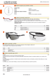
P6: SHOCK SENSOR (supplied with alarm kit, part no. ALA-OP)
Install Shock Sensor in a place where it will provide omni directional sensitivity.
P7: OTHER SENSOR (supplied with alarm kit, part no. ALA-OP)
This connector is used to connect other types of sensors, such as a motion sensor,
window breakage sensor or any other type of sensor that provides a
negative pulse of at least 0.7 second.
This input can also be programmed in Trunk supervision. This way, the
trunk supervision will be temporarily canceled (5 minutes) while the trunk is
opened by a remote command;
See Stage 1 - Level 14 of programming on page 22.
WHITE – TRIGGER INPUT
BLACK – GROUND
RED - +12VDC
P9: LED (STATUS)
This connector is used to connect an external LED that indicates the users various statuses (alarm system, antitheft
and safety sequence). If the LED is installed in a location visible from outside the vehicle, it will also act as a
deterrent.
When the programming option is set as “P9 LED output indicates the status of the Alarm, Anti-theft and the Manual
Sequence” in Stage 2 – Level 4, the LED will show the AstroStart alarm status or the antitheft status, depending
which one is enabled. If installed in a manual transmission car, it will also temporarily indicate in priority, the status of
the safety sequence.
P10: TRIGGER INPUT
This is a four-pin connector that allows an AstroStart RST-2 timer
part no. 310-903-502-02 or a similar Negative pulse device to trigger the startup procedure of the remote start. A negative 0.7 second pulse is required on
this input.
To connect negative pulse devices other than a RST-2 timer unit to this input,
use the part no. 310-903-271-01harness.
14
(-) TRIGGER INPUT
P10-4
P11: VALET SWITCH
Connector allowing a push-button switch to be plugged into the module to control the “Valet” mode for both the
AstroStart alarm and the antitheft application. It is also a part of the Paging system.
“Valet” mode: Press the push-button for more than 3 seconds with the key ON and the engine NOT
running.
“Paging” mode: Press the push-button for more than 3 seconds in any condition other than the one for
the “valet” mode, will transmit a call (page) to all the remotes learned in it’s memory (2 way remote only).
This switch should be mounted in a location accessible to the operator, out of plain view.
Use a 7mm (9/32") drill bit.
P12: MANUAL INTERFACE
Five-pin connector used to connect the manual interface.
The manual interface monitors the status of the doors and parking brake for initialization of the
system activation sequence.
The purpose of this sequence is to increase safety by forcing the user to ensure that the gearshift
lever is not in gear when leaving the vehicle and planning to remote start it later.
P13: MAIN SWITCH
Three-pin connector designed for a plug-in on/off switch. This switch overrides the remote start functions, while
maintaining all other functions.
The switch should be mounted in a location easily accessible by the operator, such as under the dashboard, where
the driver can reach it easily. The round shape of the switch allows you to install it on the dashboard, using a 1/2"
drill bit.
P15: RECEIVER CONNECTOR
A four-pin connector for direct connection to the supplied receiver.
Mount the receiver module below the tinted strip on the windshield, or if windshield has no tinted strip, about 10 cm
(3-1/2") from the roofline, with the connector facing up.
NOTE: If the windshield is of the heated variety, an alternative location must be selected, as a windshield of
this type will impede reception of the remote control signal.
P16: IM – OM – IOM ACCESSORIES CONNECTOR
This is an eight-pin connector designed to plug directly into an AstroStart alarm/anti-theft interfacing module.
All dedicated devices interfacing
the remote start module to an
OEM or immobilization alarm will
be equipped with a connector
allowing connection to this P16
location.
DESCRIPTION OF HARNESS
BROWN: OUTPUT (-) LOCKING
BLUE: OUTPUT (-) UNLOCKING
BROWN/WHITE: PROGRAMMABLE OUTPUT 1 (-)
WHITE/BLUE: PROGRAMMABLE OUTPUT 2 (-)
ORANGE: OUTPUT ANTI-THEFT (-)
GREEN: OUTPUT (-) WHEN RUNNING
BLACK: GROUND
RED: +12VDC
Note: The Green (P2-6), Orange (P2-7), White/Blue (P2-14) and the Brown (P2-13) are linked to the P16
connector by the internal board. If these wires are used on both connectors, isolate them with diodes.
15
Detailed programming of the control module
Programming procedure
Programming is accomplished using 9 Dipswitches incorporated into the module or a programming console that
communicates with the control module through the receiver connector. This console is called Multitest II and can also
be used as a diagnostic tool. I.e.: alarm code, start fail codes.
Programming is very simple once you have programmed your first module. In most cases, you will need to program
only the tachometer and cylinder settings, and occasionally an additional remote transmitter.
Programming parameters are divided into 2 different Stages.
Stage 1 is separated into 16 groups called "levels" while Stage 2 is separated into 4 Levels.
STAGES PROGRAMMING
The fist step is to identify which Levels in which Stages need to be modified. Default, you are in Stage 1. So you only
need to modify the Levels that require it, according to the procedure described later. But if changes are required in
Levels under Stage 2, you need to access these by the following procedure:
1.
Put Dip switch number 5 (and 5 only) to the ON position
2.
Press on the brakes. The LED of the control module will light up, indicating that you’re in Stage 2 and
will stay lit as long as you’re in that Stage.
You will remain in Stage 2 as long as any of the Dipswitches 1 to 4 are on. To exit Stage 2, turn all
Dipswitches to off, especially Dip 1 to 4, and press on the brakes.
LEVELS PROGRAMMING
Programming Levels need to be read in 2 separate parts. The first one, Dip switches 1 to 4 are used to select
programming levels while Dip switches 5 to 9 are used to select options in each level.
SELECTING LEVEL
SETTING OPTIONS
Programming is done as follows:
1)
Set Dipswitches 1, 2, 3 and 4 to select the LEVEL of the desired feature.
2)
Set Dipswitches 5 to 9 to combine OPTIONS you wish to select.
NOTE: IF YOU HAVE TO MAKE ANY PROGRAMMING CHANGES IN ONE LEVEL, THE ENTIRE LEVEL
MUST BE PROGRAMMED.
3)
Press on the brakes to lock in the selected parameters in memory. LED will flash the same number of
times as the programming level selected, confirming that parameters have been memorized in that
LEVEL. In Stage 2, the LED also confirms by flashing but in reverse. (1 flash: ON-OFF-ON)
4)
Repeat steps 1 to 3 for each LEVEL that requires programming changes.
5)
When programming is complete, put all Dipswitches back to OFF position, then press on the brakes.
Example: Imagine you have to program the AstroStart for an eight-cylinder engine, with an idle speed of 600 RPM.
16
1)
Place DIP switches to select the Level: Dipswitch 1 (On), 2, 3
and 4 (Off) to select level 2.
2)
Place DIP switches to select Options: DIP switches 5, 6 (Off)
and 7 (On) to set for 8 cylinders and DIP switch 8 (On) and 9
(Off) to set the idle speed of 600 RPM.
3)
Press on the brakes; the LED flashes twice to confirm LEVEL
2 settings have been memorized.
4)
Proceed with next level, or, if all programming is done, put all Dipswitches back to OFF and press on the
brakes.
SETTING EXAMPLE
Programming Tables
In the following tables, the shaded option is the default setting.
TRANSMITTER CODE LEARNING
STAGE 1 - LEVEL 1
5
6
7
8
9
Initiate STAGE 2 of programming
Initial Programming Reset
DEFAULT SETTING:
Transmitter Learning
Normal operation
Normal Operation
AUTOMATIC TACH LEARNING
CANNOT BE PROGRAMMED UNTIL INSTALLATION IS COMPLETE
Note: Vehicle engine has to be warmed up before doing any programming.
Place DIP switches as illustrated,
start the vehicle using the key, and then press on the brakes.
The tach learning function takes a little over 4 seconds.
After this delay, the unit will come out of tach learning mode.
When tach signal is detected, LED will flash the same number of times as the number of cylinders selected.
If tach learn mode fails, the control module programs actual settings for DIP switches 8 & 9
(idle speed) and the cylinder setting will remain the same as it was before programming started
(see LEVEL 2 programming).
An installer can therefore change the parameters of Dipswitches 8 & 9 without worrying about the number of
cylinders previously programmed.
The technician would simply have to put Dipswitches 1, 5, 6 & 7 to automatic tach learning mode,
without starting the vehicle.
This way, tach learning mode will fail, which will maintain the original cylinder setting but allow you to
program the new idle speed.
TACH AND CYLINDERS
STAGE 1 - LEVEL 2
5 6 7 8 9
1 Cylinder
Default settings:
1 cylinder; 800 RPM
2 Cylinders
3-4 Cylinders
5-6 Cylinders
8 Cylinders
IN MOST CASES, IT IS RECOMMENDED TO USE
THE AUTOMATIC TACH LEARNING OPTION AS
LONG AS ENGINE HAS BEEN PREVIOUSLY
WARMED UP.
10 Cylinders
12 Cylinders
Automatic Tach Learning
Hybrid Engine (See P2-10 p.11)
800 RPM
600 RPM
500 RPM
17
ENGINE CONFIGURATION
STAGE 1 - LEVEL 3
Default settings:
Circuit P2-5 (Orange/White) is
use to monitor: the Parking Light
Glow plug delay: 15 seconds
Parking Light or Glow Plugs circuit
polarity2: Positive
Ignition: Turned Off between crank
attempts
Hood pin switch: N.C.
Circuit P2-5
(Orange/White)
used to monitor
Glow Plug delay
Parking Light or
Glow Plugs circuit
polarity *2
Ignition circuit
status between
crank attempts
Hood Pin
switch type *3
5
6
7
8
9
Parking Light
Glow Plug *1
15 sec.
30 sec.
Positive
Negative
Turned Off
Remains On
Normally Closed
Normally Open
1 - When the unit is set to monitor the Glow plug circuit, the runtime is
twice the setting done.
2 - Positive & Negative settings glow plug are based on the circuit being
activated. (Parking Light or Glow Plug light “ON”)
3 - Hood Pin switch type: Normally open & normally closed settings
are based on the hood being “Open”.
ANTITHEFT SYSTEM
STAGE 1 - LEVEL 4
Default settings:
Rearming = Disabled
Rearming type = Type 1
Accessory = No delay
Antitheft = Disabled
Antitheft type = Passive
Note: Type 1 is use to duplicate the oem
alarm rearming that requires a Lock
command while the driver’s door is open.
(i.e. GM) Type 2 is suited to shut down RAP
by opening and closing the driver’s door
prior to Lock.
18
OEM security
system rearming
Rearming type
Accessory
Start-up Delay
5
Disabled
Enabled
Type 1
Type 2
No delay
3 sec. delay
Disabled
Antitheft System
Enabled
Passive
Active
6
7
8
9
PROGRAMMABLE OUTPUTS 1, 2, 3 & 4
STAGE 1 - LEVEL 5, 6, 7 & 8
Output 1:
P2 Connector, Pin 13
Brown wire
Default setting:
Pulse before start
DEFAULT
LEVEL
Pulse Before Start
(Default Output #1)
5
Pulse After Shutdown
(Default Output #2)
6
5
6
7
8
9
Ground While Running
Park Lights
Pulse After Startup
Pulse on 2nd Unlock
Output 2:
P2 Connector, Pin 14
White/Blue wire
Default setting:
Pulse after shut-down
Ignition
Accessory
Starter
Trunk Release
(Default Output #3)
7
Pulse after Ignition Off
(1 min. duration)
Dome Light
(Default Output #4)
Output 3:
P2 Connector, Pin 15
White wire
Default setting: Trunk release
8
Ground when locked
Utility 1
Utility 2
Utility 3 (1 second fixed time)
Utility 4 (1 second fixed time)
Ground when Safety sequence
is Valid
Output 4:
P2 Connector, Pin 16
Purple wire
Default setting: Dome light
Ground when the security system
(AstroStart or OEM) is triggered or
when the Panic mode is engaged
Ground when Unlocked by User 2
External LED (Same functions as P9)
Deactivated
19
PROGRAMMABLE RELAY
STAGE 1 - LEVEL 9
P5 Connector
Default setting: Ignition
5
6
7
8
9
5
6
7
8
9
Pulse Before Start
Pulse After Shutdown
Active While Running
Parking Lights
Pulse After Startup
Pulse on 2nd Unlock
Ignition
Accessory
RELAY ACTIVATE BY
CONTROL UNIT
Starter
Trunk Release
Pulse after Ignition Off (1 min. duration)
Dome Light
Horn
WIRING DETAILS
RELAY
P5 PIN #
CONTACT
1
2
3
30
87A
87
Utility 1
Utility 2
Utility 3 (1 second fixed time)
Utility 4 (1 second fixed time)
Active when the security system (AstroStart or OEM)
is triggered or when the Panic mode is engaged
Active when Unlocked by User 2 (See detail on p.27)
Deactivated
LOCK/UNLOCK OPTIONS
STAGE 1 - LEVEL 10
Default settings:
Pulse before Ignition duration
Pulse before ignition = 0.7 sec.
Unlock = 0.7 sec.
Door Lock/Unlock Pulse
Auto lock = Disabled
Unlock Pulse = Single
Second Lock
Confirmation = Disabled
Auto lock
Unlock Pulse
Second Lock Confirmation
20
0.7 sec.
0.35 sec.
0.7 sec.
2.8 sec.
Disabled
Enabled
Single
Double
Disabled
Enabled
DURATIONS: UTILITY 1 & 2 & PANIC
STAGE 1 - LEVEL 11
Utility 2 = 0.7 sec.
6
7
8
9
5
6
7
8
9
5
6
7
8
9
0.7 sec.
Default settings:
Utility 1 = 0.7 sec.
5
Utility Duration 1
Panic duration = 30 sec.
15 sec.
1 minute
8 minutes
0.7 sec.
Utility Duration 2
15 sec.
1 minute
8 minutes
Panic Duration
30 sec.
60 sec.
ENGINE RUNTIME
STAGE 1 - LEVEL 12
Default settings:
RPM > 3000
RPM > 3000 = Enabled
Pulse before start on all Unlock
outputs = Disabled
Pulse after Start on all Lock
outputs = Disabled
Engine runtime
8 min. (Gas)
16 min. (Diesel).
Enabled
Disabled
Pulse before start
on all Unlock outputs
Disabled
Pulse after start
on all Lock outputs
Disabled
Enabled
Enabled
2 / 4 minutes
Engine runtime
(Gas / Diesel)
4 / 8 minutes
8 / 16 minutes
18 / 36 minutes
SENTINEL MODE
STAGE 1 - LEVEL 13
Default settings:
Pulse before on
Trunk command = Enabled
Temperature = -15° C (5° F)
Run time
= 8 min. (Gas),
= 16 min. (Diesel)
Pulse before on
Trunk command
Disabled
Enabled
-5° C (23° F)
Sentinel mode
Activation Temperature
-15° C (5° F)
-20° C (-7° F)
-30° C (-22° F)
4 min./ 8 min.
Sentinel mode Runtime
Gas / Diesel
8 min./ 16 min.
18 min./ 36 min.
21
ALARM
STAGE 1 - LEVEL 14
5
6
7
8
9
5
6
7
8
9
5
6
7
8
9
Alarm Disabled
Default settings:
AstroStart Alarm: Disabled
AstroStart Alarm
Chirp: Enabled
Additional sensor
programmed in: Other Sensor
OEM alarm detection through
the horn (Alarm Link): Disabled
Active Arming
Semi-Passive Arming
Passive Arming
Chirp
Additional Sensor
configuration
OEM alarm detection
(Alarm Link)
Enabled
Disabled
Other sensor
Trunk supervision
Disabled
Enabled-See page 9
REMOTE SETTING
STAGE 1 - LEVEL 15
Default settings:
Trunk command:
activates Trunk output
Activates Trunk output
Trunk command
Activates Utility 1 output
VEHICLE TYPE
STAGE 1 - LEVEL 16
Default settings:
Vehicle Type
Vehicle Type = Manual
Transmission
Manual Transmission
See Note 1
Automatic transmission
2 Parking
brake activation
Manual safety sequence
initialized by:
2 Parking brake activation
1 Parking
brake activation
See Note 2
Manual sequence
initialized by:
Activation and
deactivation by
Remote control
See Note 3
Activation by
Remote control
and deactivation when
door is closed
Note 1: If any one of the Dipswitches 5, 6 or 7 is in the OFF position, level is set
to MANUAL TRANSMISSION MODE. The module automatically sets to
Manual Transmission mode when an interface is connected.
Note 2: The safety sequence initialized by a single parking brake activation
is less recommended since it is transparent and users could release the
clutch pedal before realizing the engine is still running.
Note 3: The Turbo mode cannot be used with this mode
22
STAGE 2
ACCESSORY & PARKING LIGHT RELAY
DEFAULT
LEVEL
STAGE 2 - LEVEL 1 AND 2
5
6
7
8
9
5
6
7
8
9
5
6
7
8
9
Pulse Before Start
Accessory Output
P4 Connector, Pin 2
Default setting:
Accessory
Pulse After Shutdown
Activated While Running
Parking Lights
2
Pulse After Startup
Pulse on 2nd Unlock
Ignition
Accessory (not available on P4-3)
1
Starter
Trunk Release
Pulse after Ignition Off (1 min. duration)
Parking Light Output
P4 Connector, Pin 3
Dome Light
Default setting:
Parking Light
Utility 1
Note: The « Accessory » option
is not available on this output.
Utility 3 (1 second fixed time)
Horn
Utility 2
Utility 4 (1 second fixed time)
Deactivated
STAGE 2
MISCELLANEOUS CONFIGURATIONS
STAGE 2 - LEVEL 3
Start confirmation
on demand
Default settings:
Start confirmation
on demand: Enable
2nd Lock confirmation type
2nd Lock confirmation with Horn
Turbo Mode: Disable
Dome light activation
when engine stop: Disable
Turbo Mode
Turbo Mode runtime
Dome light activation
when engine is stopped
(by the Key)
STAGE 2
Enabled
Disabled
Horn
Siren
Disabled
Enabled
1 minute
2 minutes
Disabled
Enabled
MISCELLANEOUS CONFIGURATIONS (2ND PART)
STAGE 2 - LEVEL 4
P9 LED output indicates
Default setting:
P9 LED output indicate the status the status of:
of: the Alarm, Anti-theft and
Manual Sequence
Alarm, Antitheft and
Manual Sequence
Safety Sequence
Only
23
Diagnostic Codes
When the module is in operating mode (ready to start), the LED may display different diagnostic codes for
troubleshooting. It flashes a certain number of times (see table) after an unsuccessful attempt to remote start or after
a runtime interruption. The numbers of flashes depend on the reason for shutdown.
Codes can also be read on the parking lights after a request from the remote. See the “Table of commands” in the
owner’s guide.
CODE
REASON FOR INTERRUPTION
1
Stopped by remote control / trigger input - P10.
2
Stopped by pressing on the brakes, (-) outputs are overloaded or faulty ground.
3
Shutdown controlled by alarm condition
4
No tachometer reading (rpm).
Note: If the engine does not crank during a start cycle, it is normal that no tachometer signal is
generated. This can happen when the vehicle is equipped with an immobilization system (Anti-start).
Make sure this system is correctly interfaced.
5
Hood opened.
6
Stopped by manual interface (Invalid safety sequence).
7
Ignition already in "ON" position.
8
Disabling switch in "OFF" position or thermal protection (P2-9 and/or P10 to P16 overloaded).
9
Run time expired.
10
Remote start failed after three attempts.
Note: If the engine starts, then immediately stops for no apparent reason during a start cycle, it may be
that the vehicle is equipped with an immobilization system (Anti-start). Make sure this system is correctly
interfaced.
11
Tachometer signal already present at Start attempt.
12
RPM above 3000 (if "Enabled" at Level 12). Verify your tachometer setting.
Note: Can be caused by inadequate setting of number of cylinders.
13
RPM below idling.
Note: Can be caused by inadequate setting of number of cylinders.
14
Safety sequence broken by parking brake.
15
Safety sequence broken by opening a door.
16
Internal failure.
17
Module programming is done through receiver plug (Multitest II).
19
Manual interface not connected correctly to remote start module.
20
Manual interface detected when the unit was programmed in “Automatic transmission”.
SAFETY SEQUENCE NOT ACCEPTED
If the control module refuses to validate the safety sequence, note that the code must be read before brakes are
pressed or a start command is sent, because this will replace the current code with code 6 and you will have no
indication of the reasons for failure to start.
If no code is generated, the manual interface may be the cause for one of the following reasons:
•
A door was open.
•
Parking brake was not applied.
•
Engine was not running during the sequence (no power to the ignition or no tach signal).
24
VERIFICATION OF INSTALLATION
Make sure that the module is set to desired mode, Automatic Transmission
, at Stage 1 - Level 16 of programming
or Manual Transmission
before proceeding with main harness test.
STEP 1: ENGINE TAKEOVER TEST (CONTINUOUS MODE)
This test will help you verify if all required vehicle circuits are properly powered up with the remote start.
Programming should be performed before attempting to check the system since some outputs (e.g. immobilizer,
additional ignitions) need to be configured properly to prevent error codes from being stored in the vehicle’s ECM.
Check connections to the P4 harness with the following test:
Close all doors.
Put gearshift lever in neutral (N) and release the parking brake.
Start vehicle with ignition key.
Activate parking brake once or twice, depending on the module programming (the purpose of this
is to allow the control module to take over the engine).
Activate continuous mode doing the Start command (2 commands are required if Turbo mode’s
enabled)
Withdraw key from the ignition switch.
The engine should keep running. Make sure that all functions operate properly:
no warning indicators;
charging system;
climate controls;
parking lights;
If any of these features fail to operate or if the engine stalls, additional relays may be required to activate additional
circuits or a programming may need to be changed. Read the diagnostic code on the control module LED and refer
to the table of diagnostic codes on page 24 for a description of the problem.
STEP 2: FULL START TEST
WARNING!! There is no need to attempt a remote start if the Engine takeover test procedure fails.
Start vehicle using the remote transmitter.
For manual transmission, execute the safety sequence, as programmed in Stage 1 - Level 16 and described in
the User Manual.
The vehicle should start and run normally with the circuits functioning correctly as in Step 1 above.
Note: When the remote starter is installed on a vehicle equipped with a transponder type immobilization system, it is
preferable to complete the installation of the control module and to test it before proceeding with the connection of
the interface that neutralizes the vehicle's immobilization system (anti-start). To do so, test the remote starter with a
key inserted in the key cylinder. Do not turn the key.
If everything works fine, install the immobilizer interface and make sure that the vehicle can still be
remote started.
If the vehicle does not start, see the diagnostic code reference chart. This code will tell you where
to look to solve the problem. You’ll need to solve this problem and have the remote starter working
with a key inserted in the key cylinder before installing the immobilizer interface to the vehicle.
25
POST-INSTALLATION AND SECURITY TESTS
When installation is complete, check all safety devices.
Make sure that the engine does not start or that it stops when:
disabling switch is in "OFF" position;
hood is opened;
engine speed exceeds 3000 RPM; (if programmed in Stage 1 - level 12)
brakes are applied.
Also check that all functions/devices operate normally during a remote start.
Pay attention to the following points:
vehicle charging system;
heating and air-conditioning system;
door-lock functions (remote control);
run time (programming);
starter does not grind when engine starts;
all options (defogger, trunk release, etc.);
remote control range;
LED on main unit.
For manual transmission vehicles, in addition to the standard safety checks, make sure that
opening ANY door breaks the safety sequence.
Proceed as follows:
1.
2.
3.
4.
5.
6.
7.
Execute the safety sequence as described in the User Manual.
Remote start and stop the engine to confirm that the sequence is valid.
Open and close one door only.
Try to remote start engine again to confirm that opening that door broke the sequence.
Engine MUST NOT START. If it does, it means the manual interface cannot detect the opening of the door.
Check the door circuit connections then repeat test at step 1.
Repeat steps 1 through 5, making sure you open A DIFFERENT DOOR in step 3, until ALL THE DOORS
have been checked, INCLUDING THE HATCHBACK.
Repeat steps 1 through 5, but this time by releasing the parking brake in step 3.
Note: If the rear seats fold down, the trunk should be considered as a door. You will have to add a trunk detection
switch. See "Connecting the Door Switches and Motion Detector" in the Manual Interface instruction.
Part no. RS-MI.
THE INSTALLATION IS NOT SAFE IF
OPENING ANY DOOR DOES NOT BREAK THE
SAFETY SEQUENCE THAT NEUTRALIZES THE START.
THERE IS A RISK THAT THE GEARSHIFT LEVER CAN BE LEFT OR
PLACED IN GEAR WITHOUT THE SYSTEM BEING ABLE TO DETECT IT.
THIS MEANS THAT THE SYSTEM COULD EXECUTE A REMOTE START WHILE IN GEAR.
26
CODE LEARNING OF TRANSMITTER (S)
ALL REMOTES INCLUDED IN ASTROSTART REMOTE STARTER KITS ARE FACTORY PROGRAMMED. THERE IS NO NEED TO
PROGRAM THEM AT THE INSTALLATION.
Remote programming can be done in two different ways:
WITH THE DIP SWITCHES
The easiest and fastest way, when you have access to the control module, is by the Dipswitches.
Simply put the Dipswitch #8 to ON and press the brakes.
Enter all desired remotes, one after the other, to the memory slots of the control module by pressing any
button of the remote. (Be careful not to send a Panic command). When the programming of the remote
is done, the parking light switch will flash once and the control module LED will blink rapidly.
Repeat the above procedures for each remote control that has to be programmed. A maximum of 4
remotes can be programmed into a single control module.
Note: When the first code learning command is sent, all the old codes are cleared out. Therefore,
if you want to add a new remote, all the old ones must be reprogrammed as well.
Once the programming of all remotes is done, put Dip switch #8 back to OFF and press the brakes.
Remote(s) is (are) now programmed to the system and ready to use.
The memory slots 3 and 4 activate an output called “Ground when Unlock by User 2” allowing
different functions in the vehicle to be controlled by a different user when Unlocking.
WITH THE IGNITION KEY
One or more remote transmitters can be added without needing to access the remote start control module. To do so,
the programming is accessed as follows:
Open the hood and make sure the switch is making contact
Place key in the ignition and turn to the “RUN” position
Press on the brakes once
Within 10 seconds, turn the key from “RUN” to “STOP” position 3 times. If this sequence is correctly
carried out, the control module will flash the parking lights (4 flashes). You may then proceed to the next
step.
Press any button on the new remote control (be careful not to send a Panic command).
When access code of the new remote control is memorized, the control module will confirm with flashing
parking lights (1 flash).
Repeat the above procedure for each remote control that has to be programmed.
Note: When the first code learning command is sent, all the old codes are cleared out. Therefore,
if you want to add a new remote, all the old ones must be reprogrammed as well.
Once the remotes are learned, press on the brakes.
Remote(s) is (are) now programmed to the system and ready to use.
Memory slots 3 and 4 activate an output called “Ground when Unlock by User 2” allowing different
functions in the vehicle to be controlled by a different user when Unlocking.
27
28