1
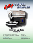
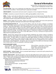
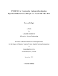
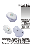
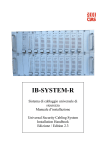
KN-8828B
Upgrade Directions
This document outlines the steps to take
to update earlier Hottop Bean Roasters to
the KN-8828B
© 2007 by Chang Yue and Hottop USA - All Rights Reserved
No part of this document may be reproduced without our written permission
Chang Yue Industrial Corp.
www.changyue.com.tw/
e-mail: [email protected]
Hottop U.S.A.
www.hottopusa.com
e-mail: [email protected]
v.1A - July21,2007
1
KN-8828B
Upgrade Directions
This document outlines the steps to take to update earlier
Hottop Bean Roasters to the KN-8828B
Table Of Contents
i - Introduction and Warnings - - - - - - - - - - - - - - - - - - - - - - - - - - - 3
1 - Remove the Control Panel - - - - - - - - - - - - - - - - - - - - - - - - - - - 4
2 - Remove the Cables from the Control Panel - - - - - - - - - - - - - - - - 4
3 - Remove the Drum - - - - - - - - - - - - - - - - - - - - - - - - - - - - - - 5
4 - Remove the Fan - - - - - - - - - - - - - - - - - - - - - - - - - - - - - 5
5 - Remove the Rear Cover - - - - - - - - - - - - - - - - - - - - - - - - - - - 6
6 - Disconnect Wires on the Main Circuit Board - - - - - - - - - - - - - - - - - 6
7 - Remove the Base - - - - - - - - - - - - - - - - - - - - - - - - - - - - - - 7
8 - Remove the Main Circuit Board - - - - - - - - - - - - - - - - - - - - - - - - - - - 8
9 - Install the KN-8828B Main Board - - - - - - - - - - - - - - - - - - - - - - - - - - - 9
10 - Attach Wires to the KN-8828B Main Board - - - - - - - - - - - - - - - - - 9
11 - Replace the Chaff Tray Safety-Switch Cable - - - - - - - - - - - - - - - - - - 10
12 - Replace the Base - - - - - - - - - - - - - - - - - - - - - - - - - - - - - - - - 11
13 - Replace the Remaining wires on the Main Circuit Board - - - - - - - - - 11
14 - Replace the Rear Cover - - - - - - - - - - - - - - - - - - - - - - - - - - - 12
15 - Replace the Fan - - - - - - - - - - - - - - - - - - - - - - - - - - - 12
16 - Replace the Drum - - -- - - - - - - - - - - - - - - - - - - - - - - - - - - 12
17 - Replace the Bearing Plate - - - - - - - - - - - - - - - - - - - - - - - - - - - 13
18 - Replace the Front Cover - - - - - - - - - - - - - - - - - - - - - - - - - - - 14
19a- Install the KN-8828B Control Panel (2-cable machines) - - - - - - - - 14
19 - Install the KN-8828B Control Panel - - - - - - - - - - - - - - - 14
20 - Complete the Assembly - - - - - - - - - - - - - - - - - - - - - - - - - - - 16
21 - Before You Roast - - - - - - - - - - - - - - - - - - - - - - - - - - - 16
i - Introduction and Warnings
KN-8828B Upgrade Procedure
These instructions will guide you through the procedure to upgrade a KN-8828, KN-8828D, or KN-8828D+
(all earlier models) or even the KN-8828P to the KN-8828B. Over the years there have been some internal and external changes to models so some of the parts shown here may vary slightly from your model, but unless otherwise
noted, the general procedure is the same for all models.
This information is presented here for your convenience and for educational purposes. Before attempting any
of the following procedures, be sure read through the procedure thoroughly and be sure that you are comfortable with
the steps listed therein.
This procedure is written with a certain amount of information taken for granted such as, but not limited to, the
proper use of hand tools and dealing with the electrical wires and connectors. These are not written as, nor meant to
be a comprehensive repair guide.
For all procedures it is best to remove all “loose” parts of the machine before beginning- these include the Cooling Tray, Rear Filter, Heat-Guard Grills, and Bean Insertion Chute Cover. Having some small containers or an egg
carton in which to place the fasteners will make reassembly easier. Label each container and place them aside with
their related parts. A large, flat working area with sufficient light will make the job easier. Be sure to cover the working surface to protect it from being damaged. Laying out a large towel will help catch any small parts which may be
dropped.
The GREEN numbers in the text [ “(3)” for example] refer to the large green numbers “3” next to the various images.
The upgrade Kit Contains:
- The KN-8828B LCD Control Panel
- The KN-8828B Main Circuit Board
- A new cable with 8 wires
- A new cable with 2 wires
- Assorted screws (Included as a courtesy and
- Tweezers
are not necessarily required for this procedure.)
The following tools will be needed:
- Phillips screwdrivers (magnetized is helpful)
- A slotted screwdriver
- A small pair of needle nose pliers
Additional items that may be needed:
- Marker pen or liquid paper pen
- A digital camera to record wire positions
- Masking or Painters’ tape
Before beginning this procedure read these warnings and proceed with care:
WARNING: Read all safety warnings and the entire instruction manual before attempting any of these
procedures. It is possible to damage the machine, and/or void your warranty, and/or cause a dangerous or hazardous
situation by following these procedures. Always unplug the machine before beginning any maintenance or repair
chores and never work on the machine until it has fully cooled to room temperature. Proceed at your own risk.
WARNING: Some parts of this machine have sharp edges and other cutting hazards. Take care to protect
yourself and the electronic and electrical components of this machine from sharp edges as you work.
CAUTION: There are electronic components in this machine that can be damaged by static electricity. Take
static precautions when handling the electronic components or their connections.
NOTE: Plan on a total time of approximately ninety minutes to three hours to complete this procedure. The
amount of time will vary depending on your skill level and experience.
3
1 - Remove the Control Panel.
1
Begin by making sure that the machine is unplugged and remove the safety
Heat-Guard Grills if so equipped.
To remove the control panel pull up one of the upper corners of the control panel
(1) just enough to allow you to place a screwdriver’s blade between the back surface
of the control panel and the side of the machine exactly in the center of the control
panel (2). There is only one retaining tab along the top edge and it is located right in
the center. The use of a strong light will assist you in locating it if you need to see
where to place the screwdriver.
Note: Covering the blade of the screwdriver with a layer of tape will help keep
you from scratching the machine.
2
3
While pulling the panel towards you, press the screwdriver downward as indicated by the green arrow (2). Increase the force at both points slowly until the tab in
the center of the panel is released.
Now work along the side of the panel most convenient to you. Along each side
there are two tabs just like the one now exposed along the top. Release the top one
first and then the bottom one using much the same method as when you released the
top tab.
Once the two tabs along the edge are free, the remaining three tabs can be easily
freed and the panel removed. For your reference, (3) shows an image of the tab along
the top of the control panel. There are a total of six tabs- two along the right side, two
along the left side, and one each on the top edge and the bottom edge.
IMPORTANT: Make note of how many cables are connected to the
Control Panel. It will be important later in the upgrade process
2 - Remove the Cables from the Control Panel.
4
Depending on your model there will be either two or three cables attached to
the circuit board of the Control Panel. Remove them, one at a time. They are different sizes and polarized so each will only go back oriented correctly and in the correct
socket, so there is no need to mark these.
The small connector (4) with two connection socket openings is the thermal
sensor. The larger plug (5) connects to the main circuit board. If you have a third cable
with three connection socket openings (with two wires attached) it is connected to the
Chaff Tray Safety Switch found only on the KN-8828D+ and KN-8828P.
5
After disconnecting the larger cable (5), push it completely through the round
opening into the roaster’s inner cavity.
4
3 - Remove the Drum
6
With the Chaff Tray removed, hold the Front Cover of the machine with one
hand and fully loosen the Gold Screw (6) by turning it counter-clockwise until the
Front Cover can be removed. Place it off to the side.
Remove the four screws that hold the bearing plate on the face of the machine.
Only remove the four screws as indicated (7). The bearing plate can now be removed
from the machine.
The drum is now exposed and ready for removal. It pulls straight out, but it is
heavy, so supporting it so that it is parallel to the sides of the roasting chamber will
help. Grasping the drum supports and twisting back a forth a bit will help. Do not
drop the drum!
7
NOTE: As you proceed notice that different types of screws are used in assembling
the Hottop Bean Roaster. Color, length and
thread type varies. Keep the screws separated and labeled to enable you to more
easily complete the assembly process.
4 - Remove the Fan
8
If you have not done so, begin by removing the rear filter and placing it aside.
Loosen all four Phillips head screws (8) indicated by the BLUE arrows which hold
the Main Fan in place, then remove them one at a time. Hold the fan against the
machine when removing the last screw.
NOTE: The early models have four fan screws located in a different location
as indicated by the GREEN arrows. As mentioned earlier, this is one of the model
variances of which the user needs to be aware.
As you lower the fan make note of the way the wires are routed so that they can
be replaced in the same location (9). Lower the fan, but take care not to stress the
wires. Carefully pull the connector through the back of the machine. Grasp the two
halves of the polarized connector and wiggle them while pulling to separate them.
The connector will only go back together in one way (10).
9
10
5
5 - Remove the Rear Cover
Loosen and then remove all eight screws
(11). Laying out a towel on the workspace before beginning helps keep screws from being
lost if dropped.
When the screws have been removed
swing the back off to the side (12) and free
the fan’s wiring harness from the opening in
the grill
11
12
6- Disconnect Wires on the Main Circuit Board
13
Before you begin it is a good idea to mark the wires with tape or use a pen-style liquid paper applicator
and mark the wires with the numbers shown above. In the image above (13) notice that all the wires are in pairs,
and the pairs can be distinguished by the type of wire, their insulation color, or the color of the insulation on the
spade connectors. If you have a digital camera, take a picture of the wires before removing them.
The following numbers will be found printed on the new board and this will make it a lot easier for you to
attach them to the new board. The wires are in pairs as follows (numbers match those printed on circuit board):
AC_L (also shown on board as T1)- Power Cord - AC Line
(mark this one so that it goes on the correct location on the new board)
AC_N (also shown on board as T2) Power Cord - AC Neutral *1
T3 + T4 - Fusible Link (thermal safety wire) *
T5 + T6 - Heating Element *
T7 + T8 - Main Drum Motor *
T9 + T10 - Cooling Tray Agitation Motor
T11 + T12 - Ejection Solenoid *
R - The seven-wire cable that connects the main board to the Control Board
(white plug in front of board, with seven wires)
After marking the wires, disconnect all the wires indicated here by an *.
*1 - The two AC leads are the only ones that need to be returned to the specific indicated connecton points on the Main
Board. The other pairs of wires are not polarized, and as long as they are retuned to their pairs connection they are fine.
For example, wire T5 can connect to either T5 or T6 and T6 can connect to either T6 or T5.
6
7 - Remove the Base
14
Remove the 4 screws (14) indicated by the yellow arrows. It is NOT necessary
to remove the other screws on the base.
Two of the screws are under the two rubber feet at the rear of the machine which
are pressed into place and held by friction. Simply pull on the feet while “unscrewing”
and “wiggling” them and they will come out. When all of these screw are removed the
base can be separated from the machine. Work carefully and be sure that no wires are
being pulled as the base assembly is removed from the rest of the machine.
Some models had a tab and slot that locks the panel that is under the cooling tray to the Side Panels. If after completing the previous step you find that the
base pivots on the upper portion of the Roaster but will not easily come off, follow
these next two steps:
On the side opposite the Control panel, pull out the rubber plug shown here
and then remove the screw located under the plug.
On the Control Panel side, after removing the Control Panel remove the
screw located in the recess seen here.
The side panels should now be able to be pulled outwards slightly to enable the base to be removed from the upper portion of the roaster.
7
8 - Remove the Main Circuit Board
15
16
With the Base free of the machine,
the main board is easily accessed. Begin by
removing the remaining wires as indicated
(15):
T1 - Power Cord - (AC_L) Line
T2 - Power Cord - (AC_N) Neutral
T9 + T10 - Cooling Tray Agitation Motor
Note that the Power leads are marked
“AC_L” and “AC_N” on the circuit board
and these should go back on the same connectors on the new board. They appear to be
the same, so mark the “AC_L” to help identify them.
Remove the two polarized connectors- the small plug with two
wires that connects the cooling fans to the main board and the larger
plug with seven wires (16) that connect to the Control Panel. Note
how the small connector’s wires are routed so as not to confuse it with
the Main Fan’s connector.
Remove the screws that secure the main board to the base (17).
All boards have at least four screws, one screw in each corner. Some
boards have a fifth screw, located near the heat sink in the middle of the
board. As with other photos in this procedure, your board may look a
little different.
After the Main Board has been removed, it is a good time to use
compressed air and blow out the machine to remove stray chaff and
other debris that may have found its way into the machine.
Take the following items you have removed from your roaster
and carefully package them for storage:
17
- If you had five screws in this step, store one of them
- The Seven-wire Connecting Cable
- The Main Board
- The Control Panel
8
9 - Install the KN-8828B Main Board
18
Before installing the new Main Board examine the male spade connectors where most of the wires connect. You will notice that they are arranged in pairs as indicated (18) by the color coding, added here for your
reference. Notice that the locations are not only numbered but they are also named right on the board. Refer to
this diagram if you have difficulty seeing where the wires connect in subsequent steps.
Place the new Main Board in the machine. The edge of the Main Board with
the row of spade connectors must be at the rear of the machine like the original board.
Use the screws removed in Step 8 (17) to fasten the new board to the base. The new
board is held in place with only four screws, one in each corner. The screw holes are
indicated on the board with white circles (19). Snug the screws down but do not overtighten.
19
10 - Attach Wires to the KN-8828B Main Board
20
Connect the wires removed in Step 8 (15). These would be (20):
AC_L (T1) - Power Cord - AC Line
AC_N (T2) - Power Cord - AC Neutral
T9 + T10 - The two agitation motor leads
As well as the two cables removed in Step 8 (16):
-The polarized connector plug for the Cooling Tray Fan
-The polarized, eight-wire harness connector that leads to the Control Panel.
You must use the new harness that came with the upgrade kit.
21
WARNING: DO NOT USE THE ORIGINAL SEVEN WIRE CABLE!
Notice that the Cooling Tray Fan plug and the new eight-wire Control Panel plug are arranged next to
each other (21). Both are polarized and will only connect in one direction.
9
11 - Replace the Chaff Tray Safety-Switch Cable
22
In Step 2 you were asked to count the number of cables that connected to the
Control Board. There are the two possible variations. You counted either two or
three cables.
If you had THESE TWO CABLES (22) GO DIRECTLY TO STEP 12:
If you have THESE THREE CABLES (23) continue here:
23
24
25
26
27
Some machines may be equipped with a Chaff Tray Safety Switch Cable that is
too short to work properly with the KN-8828B upgrade kit. For your convenience we
have included a longer cable.
Before attempting to replace the cable, check to see if your existing cable is the
correct length:
Hold the cable parallel to the edge of the side panel (24).
If there is approximately 3.75” (9.5cm)
exposed (as seen here), then you do not need to replace
the cable and you should go directly to Step 12.
If the exposed portion of the cable is substantially shorter
than shown here it is too short. Continue here:
To gain access to the switch, remove the side panel. This
is the same side panel in which the Control Panel mounts. First remove the rubber
plug (25). Then remove the two Phillips head screws which are located in the recesses
indicated by the blue arrows (26). As you remove the panel be aware that there could
be washers on the back used as spacers to align the panel. Be sure to use them when
replacing the panel. With the side panel removed, the safety switch is easily accessed
(27).
Remove the existing cable and set it aside as it will not be used. Install the
longer replacement cable that was included with the upgrade kit. It does no
matter which connector goes on which tab of the switch. Run the cable in the
same way the original was located.
Replace the side panel using the same hardware as was removed. Be
sure to align the top edge of the panel (28) so that the four tabs lock in correctly, and be sure that the front edge (29) engages along
its front edge to the side of the chaff tray opening.
28
29
10
12 - Replace the Base
As you proceed through this and the following steps, be sure no wires are
pinched or trapped when installing the base.
31
The Yellow arrows (31) indicate the location of the four machine screws (the
screws with the flat tips). The red arrow indicates an unused hole in the base. No screw
goes there.
Loosely install the 4 screws, and check that the bottom edge of the plastic side
panels properly engage the base along its top edge.
CAUTION: Be sure that no wires have been pinched inside the roaster.
Now tighten the 4 screws. Snug down just tight enough to hold the base in position- do not over-tighten.
13 - Replace the Remaining wires on the Main Circuit Board
You will note that the layout of the spade connectors on the new board is slightly different from the original. When replacing the wires on the main board be careful to get them on the correct connectors. The numbers
below refer to the numbers printed on the circuit board (also refer to image 13). The remaining connections are
as follows: *1
T3 + T4 - Fusible Link (thermal safety wire) (“SW1” and “SW2”)
T5 + T6 - Heating Element (“Heater”)
T7 + T8 - Main Drum Motor (“Motor 1”)
T11 + T12 - Ejection Solenoid (“Solenoid”)
32
At this point all the
wires to the main Circuit
Board should be connected.
Double check that all wires
are properly routed. Keep an
eye on the various wires during the following procedures
and be sure that they cannot
be pinched.
Feed the free end of the
eight-wire cable and its connector back through the hole
in the side panel.
Here are all the wires
connected to the spade terminals on the rear of the Main
Board (32). Use this photo to
double check your wiring before going to the next step.
*1 - The two AC leads are the only ones that need to be returned to the specific indicated connecton points on the
Main Board. The other pairs of wires are not polarized, and as long as they are retuned to their pairs connection
they are fine. For example, wire T5 can connect to either T5 or T6 and T6 can connect to either T6 or T5.
11
14 - Replace the Rear Cover
33
Before you replace the rear cover on the machine double check that all wires
are firmly connected and that there are no pinched wires.
Feed the fan connector and wire through the opening (33).
Hold the Rear Cover in place making sure that it is properly aligned all around
its perimeter. Insert and loosely tighten all screws. When all screws are in place and
Rear Cover is properly aligned, tighten the screws. Do not over-tighten! Snugged
into place is sufficient.
15 - Replace the Fan
34
Connect the Fan’s plug to it’s socket, and then feed the wires and connector
through the back of the machine (34). Be sure not to pinch the wires when replacing
the fan. Hold the fan in place, be sure that it is aligned all the way around and that the
wires are not pinched, and then loosely replace all four screws before tightening them.
Do not over-tighten the screws!
16 - Replace the Drum
35
First take note of the drive end of the shaft (35). That pin slips into a
slot in the drive shaft of the drum’s motor (36). Carefully insert the drum
into the roasting chamber, guiding the drum’s shaft into the motor’s drive.
Turn the drum back and forth until the pin aligns with the slot and the drum
can be moved all the way back into the roasting chamber. The face of the
drum will be roughly parallel with the face of the machine and they will be
in the same plane when it is fully inserted.
36
12
17 - Replace the Bearing Plate
37
Place the bearing plate on the face of the machine. The flange,
indicated here by the blue arrow (37), faces OUTWARDS!
WARNING: Be sure that the drum’s shaft is seated in the bearing
dimple in the center of the bearing plate. The Main Motor and/or the
Bearing Plate can be damaged if the drum is not properly aligned!
38
39
40
The bearing plate is kept in alignment by two pins on the
face of the machine. The two holes indicated here by the green
arrows (37) must align with the two pins indicated by the blue
arrows here (38).
These pins must go through the alignment holes in the
bearing Plate. Here is a close up (39) of one hole in the bearing plate (green arrow), and its respective alignment pin on
the front bezel (blue arrow).
Hold the plate against the face of the Coffee Roaster
being sure that both pins are in place and the drum is in the
bearing hole (40), and insert all four screws by hand. Before
tightening the screws, once again check for proper alignment,
then tighten the screws. Do not over-tighten the screws!
13
18 - Replace the Front Cover
Hold the front cover on the machine, align it correctly, and tighten the Gold
Screw (41) just until it is snug in place. As the next roasting session begins, readjust
the Gold Screw as described in the Owners manual.
41
19 - Install the KN-8828B Control Panel
CAUTION: Choose step 19a OR 19b depending on your machine. READ CAREFULLY:
19a - Install the KN-8828B Control Panel (2-cable machines)
Back in Step 2 you were asked to count the number of cables that connected to the Control Board.
42
Only Follow the directions in this yellow section if
your machine had these 2 cables (42):
Since you have only two cables
that connect to the Control Panel
YOU MUST REMOVE THE JUMPER
as shown here (43).
This is located on the back side of the new KN-8828B
LCD Control panel. It is the jumper that is on a 2-pin
connector. Do not remove the jumper on the three pin
connector!
43
44
1
2
Connect the two cables to the Control Panel. Be sure
each is fully seated into its socket (44):
1 - Thermal Sensor connector (two socket plug with two
wires)
2 - Main Cable that was supplied with your KN-8828B
Upgrade kit.
NOTE: The connector with the red “X” is
not used on machines with two cables.
14
19b - Install the KN-8828B Control Panel (3-cable machines)
Back in Step 2 you were asked to count the number of
cables that connected to the Control Board.
45
Only Follow the directions in this green section if
your machine has these 3 cables (45).
46
47
Since you have three cables that
connect to the Control Panel
YOU MUST LEAVE THE JUMPER IN PLACE
as shown here (46).
This is located on the back side of the new KN-8828B LCD
Control panel
Connect the cables to the Control Panel. Be
sure each is fully seated into its socket (47).
1 - Thermal Sensor connector (two socket plug with
two wires)
2 - Chaff tray Safety Switch cable (three socket plug
with two wires)
3 - Main Cable that was supplied with your KN8828B Upgrade kit.
All Models: continue with the following steps:
48
This connection (marked “PCN1” on the board)
on your KN-8828B Control Panel indicated here (48)
is not used by the consumer. Nothing should be connected to this terminal.
15
20 - Complete the Assembly
When snapping the control panel on the machine be sure to move the cables out of the way. Excess can be
slowly fed into the machine to keep them from being pinched by the panel. Now snap the panel back into place, starting at the bottom, then working up along the sides, and finally snapping the top into place.
The plastic is tough, but use care and do not flex or bend the panel or tabs more than is necessary to get the
panel into place.
Finish the procedure by replacing the remaining parts- chaff tray, rear filter, bean loading chute cover, and cooling tray.
21 - Before You Roast
You are now ready to roast with your new, programmable, KN-8828B!
Please be sure to thoroughly read the new owner’s manual that covers the operation of the new KN-8828B,
programmable control panel. The link to the manual is on our USA HOME PAGE: (http://www.hottopusa.com)
For Additional Assistance, contact us here:
Chang Yue Industrial Corp.
www.changyue.com.tw/
e-mail: [email protected]
Hottop U.S.A.
www.hottopusa.com
e-mail: [email protected]
© 2007 by Chang Yue and Hottop USA - All Rights Reserved
No part of this document may be reproduced without our written permission
16