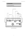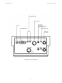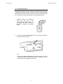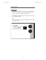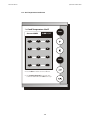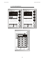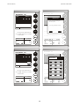
1
Instruction Manual
CyberScan PC 5500/ 5000
Bench pH, Ion & Conductivity Meter/ Bench pH & Conductivity Meter
(Also Applicable for CyberScan PCD 5500)
Technology Made Easy ...
68X292329
Rev.1 08/03
PREFACE
Thank you for selecting a Eutech Instruments CyberScan Series
5000 bench meter. This meter measures pH, conductivity and ion
(PCD5500 & PC5500 only).
The instruction manual serves to explain the use of the CyberScan
Series 5000 bench meters as a step-by-step operational guide to
help you familiarize with the meter’s features and functions. It is
structured sequentially with illustration of diagrams that explains the
various functions and setup menus available.
This manual is written to cover as many anticipated applications and
uses of the CyberScan 5000 series bench meters as possible. If
there are doubts in the use of the meter, please do not hesitate to
contact the nearest Eutech Instruments’ Authorized Distributors or
call us at (65) 6778-6876 for Eutech Instruments’ Customer Service
Dept. for assistance.
Kindly remember to complete the warranty card and mail it back to
your Authorized Distributors or Eutech Instruments Pte Ltd.
Eutech Instruments reserve the rights to change, make improvement
and modify specifications without prior notice and cannot accept any
responsibility for damage or malfunction to the instrument caused by
improper use.
©
Copyright 2002 Eutech Instruments Pte Ltd
All rights reserved. Rev.1 08/03.
TABLE OF CONTENTS
1
INTRODUCTION
2
UNPACKING THE METER
2
3
GETTING STARTED
3
1.1
3.1
3.2
3.3
4
Access pH setup
Set Sample ID#
Select Buffer Group
Set pH Custom Buffer Group
Select Buffer Recognition
Select Auto Read Mode
Set pH Stability Criteria
Set Default Temperature
Set Isopotential Point
Set Alarm Limits
Set Print Criteria
Set Print Interval
Set Data Storage Criteria
Set Display Resolution
Set Display Configuration
View Stored Data
mV SETUP
7.1
7.2
8
Access system setup
Select Language
Set Date
Set Time
Set Beeper Status
Select procedural level
Set Print Configuration
Set Baud Rate
Set Number of Bits
Set Stop Bits
Set Parity
Set Operator
Set Display Contrast
Display Meter Information
Reset to Factory Defaults
pH SETUP
6.1
6.2
6.3
6.4
6.5
6.6
6.7
6.8
6.9
6.10
6.11
6.12
6.13
6.14
6.15
6.16
7
Touch screen Operation
Choosing a channel (for PCD5500 & PC5500 only)
Button Functions
SYSTEM SETUP
5.1
5.2
5.3
5.4
5.5
5.6
5.7
5.8
5.9
5.10
5.11
5.12
5.13
5.14
5.15
6
Connectors (PCD 5500 only)
pH Electrodes & Ion Specific Electrodes (PCD5500 & PC5500 only
Conductivity Probes
USING THE METER
4.1
4.2
4.3
5
Introducing the CyberScan Series
Access mV Setup
Set Display Resolution
ION SETUP
8.1
8.2
8.3
8.4
8.5
Access Ion Setup
Select Ion Method
Select Measurement Units
Select Electrode Type
Set Significant Digits
1
1
3
6
8
10
11
12
14
16
17
19
21
23
25
27
29
31
32
33
34
35
37
39
40
41
42
44
48
50
52
53
54
56
58
60
62
64
66
68
70
72
76
77
81
83
84
86
88
90
92
9
CONDUCTIVITY SETUP
9.1
9.2
9.3
9.4
9.5
9.6
Access the Conductivity Setup
Select Cell Constant
Select Reference Temperature
Set Temperature Coefficient
Perform Replatinization
Set Significant Digits
10 pH OPERATION
10.1
10.2
Standardizing
pH Measurements
11 mV OPERATION
11.1
mV Measurement
12 ION OPERATION
12.1
12.2
12.3
12.4
12.5
12.6
Direct Reading Methods
Incremental Methods
Known Addition Method
Known Subtraction Method
Analate addition
Analate Subtraction
13 CONDUCTIVITY OPERATION
13.1
13.2
Conductivity Standardization
Measurement
94
95
99
101
103
105
109
111
113
117
119
120
121
123
129
131
135
137
139
141
143
146
14 CLEANING
148
15 TROUBLE SHOOTING
149
16 COMPLIANCE
150
17 APPENDIX
17.1
17.2
17.3
17.4
17.5
17.6
Determining Isopotential Points Experimentally
Data Management
Factory Default Settings
pH Theory
ISE Theory
Conductivity Theory
18 METER SPECIFICATIONS
19 ACCESSORIES
19.1
19.2
19.3
19.4
19.5
19.6
Replacement Meters and Adapters
General Purpose pH / ORP Electrodes SP
Specialty pH Electrode NP
pH Buffer Solutions & Single Use Sachets SP
ORP Solutions SP
Conductivity & TDS 442 Standard Solutions SP
20 WARRANTY
151
151
152
153
155
160
164
169
171
171
172
173
174
174
174
175
Instruction Manual
CyberScan PC5500/ 5000
1
INTRODUCTION
1.1 Introducing the CyberScan Series
Thank you for selecting a Eutech Instruments CyberScan Bench
meter. This manual describes the operation of the CyberScan Series
5000 bench meter. The state-of-art meter that you have purchased is
easy to operate and will guide you through the various functions by
displaying easy to understand prompts. This instruction manual
should answer any questions that might arise in operating your meter,
however, do not hesitate to call our Technical Support at (65) 6778
6876 (ext 839) or fax at (65) 6773 0836.
This bench meter provides microprocessor precision in a compact
benchtop design that is easy to use. One touch screen controls all
procedures, letting you:
Measure pH, absolute mV, relative mV or Conductivity
Select one of three sets of standard buffer groups
Implement automatic buffer recognition
Standardize with up to five standard or customer buffers
Customise your display screen and +
operating parameters
Assign operator and sample identification numbers
Store 250 data points (1000 for PCD5500) in the meter’s
memory or transfer data to a computer or printer.
Access extensive online help with just a touch a button
It all adds up to rapid, completely automatic, intuitive operation.
You will find this symbol appearing in this manual; it indicates useful
tips that ease your meter operation.
1
Instruction Manual
CyberScan PC5500/ 5000
2
UNPACKING THE METER
The following is a listing of what you should have received with your
new CyberScan meter.
Meter package includes
Meter
Power adapter (120 VAC/ 12VDC) OR (220 VAC/ 12 VDC)
depending on order code.
Electrode arm support bracket
Electrode arm
ATC probe
Instruction Manual
If any of these items are missing, please contact your nearest
Authorized Distributor.
Accessory conductivity probes and ion selective electrodes are
available and can be ordered by contacting any Authorized Distributor
or Eutech Instruments Marketing (65) 67786876.
2
Instruction Manual
CyberScan PC5500/ 5000
3
GETTING STARTED
3.1 Connectors (PCD 5500 only)
1. Review the layout and arrangement of the rear connector panel.
Back Panel of PCD 5500
3
Instruction Manual
CyberScan PC5500/ 5000
Back Panel of PC 5500/ 5000
4
Instruction Manual
CyberScan PC5500/ 5000
2. Connect the electrode arm to the base.
3. Connect the power cable to the connector cable to the rear
connector panel power jack and to a power source.
To connect RS232, see Data Management on Section 17.2.
5
Instruction Manual
CyberScan PC5500/ 5000
3.2 pH Electrodes & Ion Specific Electrodes (PCD5500 &
PC5500 only
This meter allows you to use two types of pH electrodes: the
conventional glass pH electrode and the field effect transistor (FET)
pH electrode. If both types of pH electrodes are connected, the meter
will read the FET electrode.
1. Carefully remove the protective
cover from the end of the electrode.
Before first using your glass pH
electrode, soak it 2-4 hours in an
electrode storage solution, pH 4
buffer, or KCI solution.
2. Remove the shorting cap on BNC connector. Connect the
combination pH electrode in to the BNC input connector.
If a combination electrode isn’t used, connect the indicating pH
electrode into the BNC input connector. Plug the reference
electrode into the reference pin jack. Also, install the ATC probe
into the ATC jack.
Note: be sure to connect all probes to the appropriate channel
connectors (for example: Input 1, Ref 1 and ATC1).
Option: Connect the optional FET electrode by plugging it into
the FET jack on the back meter panel. Allow the FET electrode to
warm up five minutes before use.
Connect ion specific electrodes in the same manner as pH
electrodes.
If both a conventional and a FET electrode are connected to the
meter, do not put them in a solution together because you will get
inaccurate measurements. Do not discard the BNC shorting cap.
6
Instruction Manual
CyberScan PC5500/ 5000
3. Rinse and blot-dry (don’t wipe)
electrodes
between
each
measurement. Rinse electrodes
with distilled or deionized water,
or a portion of the next solution
to be measured.
4.
Between measurements, store
conventional pH electrodes
storage solution, pH 4 buffer, or
KCI solution. Always leave the
filling hole of liquid filled
combination electrodes open.
Refill when the level of
solution
gets
below
the
manufacturer’s recommended
level.
Proper electrode care is fundamental to obtaining reliable pH
measurements. Improper care of the electrode may cause the meter
reading to drift, respond slowly, or produce erroneous readings. For
this reason, the electrode should always be conditional and used in
accordance with manufacturer’s instructions.
7
Instruction Manual
CyberScan PC5500/ 5000
3.3 Conductivity Probes
This meter allows you to use two types of conductivity cells: the 2-cell
conductivity cell with dual pin connector and the 4-cell conductivity
cell with DIN connector. If both a 2-cell and a 4-cell conductivity probe
are connected, the meter will read the 4-cell conductivity probe.
1. Carefully remove the protective
cover from the end of the
conductivity cell. Before using your
conductivity cell, soak it for 5 to 10
minutes in distilled or deionized
water.
2. Connect the 2-cell conductivity cell to the 2-cell jack. Install the
ATC probe in the ATC jack.
OR
Connect the 4-cell conductivity cell to the 4-cell jack. The 4-cell
conductivity cells have built in ATC probes. Therefore, there is
no need to install a separate ATC probe.
8
Instruction Manual
CyberScan PC5500/ 5000
3.
Rinse and blot-dry (don’t wipe)
probe between each measurement.
Rinse probe with distilled or
deionized water, or a portion of the
next solution to be measured.
4. Between
measurements,
conductivity probes dry.
9
store
Instruction Manual
CyberScan PC5500/ 5000
4
USING THE METER
EUTECH
INSTRUMENTS
11:11 am
Touch anywhere to resume
10
Instruction Manual
CyberScan PC5500/ 5000
4.1 Touch screen Operation
This new CyberScan research benchtop meter operates with a state
of art touch screen. The touch screen makes this the easiest meter
on the market to operate and care for. When this meter is first
plugged in, the STANDBY screen will appear. Touch anywhere on
this screen to access the functions of the meter.
The buttons on the right side of the screen control all of the functions
of the meter. Alight touch on the screen is all you need to access the
various functions. Once you touch a button you will get an audible
tone; the screen will not change until you lift your finger.
This design prevents rapid uncontrolled scrolling through the various
function screens. Easy to understand prompts guide you through the
operation of the meter in the selected mode. If you are ever in doubt
about what to do, just touch help on the bottom right corner of the
screen for detailed information about the screen.
The touch screen is made of a durable polyester material that is
chemically resistant. Maintenance is simple with this meter. To clean
the screen you just need to wipe it with a damp cloth and dry it with a
clean dry towel. For additional information, see cleaning and
troubleshooting section of the manual (page 149).
11
Instruction Manual
CyberScan PC5500/ 5000
4.2 Choosing a channel (for PCD5500 & PC5500 only)
Main Screen
Channel Screen
EUTECH
EUTECH
pH
INSTRUMENTS
CyberScan PC 5500
CyberScan PC 5500
mV
Select from the options to the right
Select from the options to the right
Cond
setup
January 15, 2002
11:11 am
Measure
pH
channel 1
1
9.295
2
ID#
00000
auto buffer
ON
ATC
25.0°C
slope
000.0%
mV
0000.0
Buffers Last std: Jan 15 @ 11:11 am
January 15, 2002
11:11 am
µS/cm
channel 1
0.010
ID#
STND
00000
2
dual
Ion
January 15, 2002
1
INSTRUMENTS
ATC
26.2°C
Ref
25°C
Co
0.00%/°C
Last std: Jan 15 @ 11:11 am
Dual Screen
12
11:11 am
Cond
Instruction Manual
CyberScan PC5500/ 5000
The CyberScan PCD5500/ PC5500 are multi-channel meters. With
this meter you can switch from channel 1 to channel 2. You can also
view both channels at the same time by accessing the dual channel
mode. If you set the meter to view both channels, you cannot change
the parameters without choosing the screen that you want to modify.
The setup parameters for each screen independently of one another.
Choosing a channel
1. Touch anywhere on the standby screen.
OR
Touch channel on the main screen
THEN
2. Touch 1, 2 or dual to access the channel that you want to view.
To access System Setup from the standby screen
1. Touch anywhere on the standby screen.
2. Touch 1, 2 or dual to access the channel that you want to view.
3. Touch setup.
4. Touch system on the setup screen.
If you are in any measure made, touch mode until you access the
main screen.
13
Instruction Manual
CyberScan PC5500/ 5000
4.3 Button Functions
The touch screen of your CyberScan bench meter has “buttons”
along the right side of the screen that are common to many of the
screens. The following indicates the function of these common
buttons.
This is the standby button and it allows you to access the
standby mode. When in standby, the meter will not take
measurements. It is in a state of rest. When you touch stdby
the meter will return to the standby screen which says “Eutech
Instruments” and displays the time.
This button allows you to access the channel screen to choose
what channel you want to view. This button appears only on
dual-channel meters such as PC 5500 and PCD 5500. This
button also allows you to move from the main mode to the
channel screen to access the standby mode.
mode
enter
save
The mode button allows you to switch between the various
operations of the meter. These operations, depending upon
which meter you have, include four measuring modes (pH, mV,
ion and conductivity) as well as a setup mode.
The enter button allows you to accept any changes that you
have made on one setup screens or accept values that you
have input with keypads. When touched, enter will save the
changes and return you to the previous screen.
The save button allows you to save multiple changes that you
have made on one screen as a group. It functions like the enter
button does for an individual changes.
The exit button allows you to leave the screen you are
currently viewing and return to the previous screen without
making any changes.
The help button allows you to access helpful information on
any screen. When you touch the help button, information about
the current screen appears. This information will include step
by step instructions for operating the meter from the current
screen and possible applications information for that screen.
close
The close key appears on the bottom of all help screens and
allows you to exit the help screen and return to the previous
screen.
more
The more button appears on the help screens and allows you
to advance to the next help screen for additional information.
back
The back button appears on the help screen and allows you to
move back to a previous help screen.
14
Instruction Manual
CyberScan PC5500/ 5000
std
This button accesses the standardization screen from the
various measurement modes and initiates standardization of
the meter once the standardization screen is accessed.
meas
This button is the measure button and directs the meter to
measure your sample when in the Auto Read function of the
pH mode.
setup
print
This button will access the setup screens for the measuring
mode that you are currently using. It can also be used to
access the system setup screen that allows you to set
parameters that are not related to measurements such as the
times and the date.
The print button will send information to the output device that
you have connected to your CyberScan meter. The output
device can be a printer, data logger or a computer. In addition
to this, touching the print button will also send data to the data
storage center of the meter if a sample ID # has been assigned
to your sample.
S
The arrow keys on he screen move the cursor up and down in
order to highlight parameters that you would like to review or
edit.
edit
The edit button appears on the setup screens. After you have
highlighted a parameter that you would like to change, the edit
button allows you to access the available options for that
parameter.
clear
The clear button allows you to remove a setup parameter or
standard buffer value from the meter’s memory that may have
been entered at a previous time or by a previous user that is no
longer of value to you. Touching the clear button erases the
value so you may enter a new one. It can also erase the data
from the memory of the meter.
BS
BS
The BS button is a backspace button. It appears on keypad
screens and it allows you to back up and delete a character
entered in error.
delete
The delete button appears on the “View Stored Data” screens.
This button allows you to erase the data from the memory of
the meter.
prev
The prev button appears on the Data Screens when the data
stored in the meter’s memory has been accessed. It allows you
to scroll through data points sorted and stored prior to the
current data point displayed.
next
The next button appears on the Data Screens when the data
stored in the meter’s memory has been accessed. It allows you
to scroll through data points sorted and stored prior to the
current data point displayed.
15
Instruction Manual
CyberScan PC5500/ 5000
5
SYSTEM SETUP
System Setup
SYSTEM SETUP OPTIONS
S
- Select Language
T
- Set Date
- Set Time
- Set Beeper Status
- Set Print Configuration
- Set Operator
- Set Display Contrast
- Display Meter Information
- Reset to Factory Defaults
16
edit
Instruction Manual
CyberScan PC5500/ 5000
5.1 Access system setup
EUTECH
EUTECH
1
INSTRUMENTS
CyberScan PC 5500
CyberScan PC 5500
2
dual
Select from the options to the right
pH
INSTRUMENTS
mV
Ion
Cond
Select from the options to the right
Cond
setup
January 15, 2002
11:11 am
January 15, 2002
Setup
11:11 am
System Setup
pH
SYSTEM SETUP OPTIONS
S
- Select Language
- Set Date
mV
- Set Time
T
- Set Beeper Status
- Set Print Configuration
- Set Operator
Ion
- Set Display Contrast
- Display Meter Information
- Reset to Factory Defaults
Select from the options to the right
Cond
setup
17
edit
Instruction Manual
CyberScan PC5500/ 5000
The system setup function allows you to customise the meter display
options to meet your personal preference. Once set, these will rarely
need to be changed.
To access System Setup
1.
Touch anywhere on the standby screen
2.
Touch setup on the main screen
3.
Touch system on the setup screen
The system setup options are now displayed on the screen.
To access a System Setup option
1.
Use the arrow keys to scroll through the setup options and
highlight the option to be reviewed.
2.
Touch edit to view the current status of the selected option.
The following is a detailed description of the system setup option
screens
18
Instruction Manual
CyberScan PC5500/ 5000
5.2 Select Language
Set Language
Current LANGUAGE
English
S
English
T
French
German
Spanish
enter
Use arrow keys to highlight desired language
and then touch enter to accept
19
Instruction Manual
CyberScan PC5500/ 5000
This option allows you to choose the language in which all prompts
and directions will appear on the touch screen.
To Select Language
1. Access the select language screen from the system setup
screen. The current language is displayed on the screen.
2. Use the arrow keys to highlight the desired language
3. Touch enter to accept the language and return to the system
setup screen.
OR
Touch exit to return to the system setup screen, without making
any changes.
20
Instruction Manual
CyberScan PC5500/ 5000
5.3 Set Date
Set Date
enter
Current MM/DD/YY
1
2
3
4
5
6
7
8
9
D/M/Y
clear
BS
0
/
Touch clear to delete current date
Use numeric touchpad to input the new
date and then touch enter to accept
21
Instruction Manual
CyberScan PC5500/ 5000
This screen can be used to set the present date which will be
displayed on the measure screens. This date will also be printed on
demand and stored in the data storage center of the meter when data
is saved. There are two format options for the date: month/ day/ year
(M/ D/ Y) or the European format of day/ month/ year (D/ M/ Y)
To Set Date
1. Access the Set Date screen from the System Setup screen. The
current date and numeric keypad are displayed on the screen.
2. Touch clear to delete the current entry.
3. Touch D/ M /Y or M/ D/ Y to set the date format.
4. Use the numeric touch pad to enter the desired date, separating
the day, the month and the year by touching the / key on the
keypad.
5. Touch enter to accept the date in the current format.
OR
Touch exit to return to the system setup screen, without making
any changes.
If you do not use “/”, the meter will not accept the date entry.
22
Instruction Manual
CyberScan PC5500/ 5000
5.4 Set Time
Set Time
enter
Current 12HR:
10:40 am
1
2
3
4
5
6
24hr
pm
7
8
9
clear
BS
0
/
Touch clear to delete current time
Use numeric touchpad to input the new
time and then touch enter to accept
23
Instruction Manual
CyberScan PC5500/ 5000
This screen can be used to set the present time which will be
displayed on the measure screens. This time will also be printed on
demand and stored in the data storage center of the meter when data
is saved. There are two formats options for the time. The clock can
be set as either a 12 hour clock or a 24 hour clock.
To Set Time
1. Access the set time screen from the System Setup screen. The
current time and numeric keypad are displayed on the screen.
2. Touch clear to delete the current entry.
3. Touch the 24hr or 12hr button to format the clock as either a 12
hour or a 24 hour clock.
Current 12HR
5:15 pm
Current 24HR
17:15
4. Touch am or pm to set the appropriate time.
5. Use the numeric touch pad to enter desired time, separating the
hour and the minutes by touching the “:” key in the keypad.
6. Touch enter to accept the time in the current format
OR
Touch exit to return to the System Setup screen, without making
any changes.
If you do not use the “:”, the meter will not accept the time.
24
Instruction Manual
CyberScan PC5500/ 5000
5.5 Set Beeper Status
Set Beeper Status
S
Current BEEPER STATUS
- After STABLE Readin
OFF
- After KEY Touch
OFF
- On LIMIT Exceeded
OFF
T
ON
Use arrow keys to highlight beeper
option and then touch ON/OFF to
change
Touch save to accept changes
25
save
Instruction Manual
CyberScan PC5500/ 5000
This screen allows you to turn on or off the beeper. You may choose
to have an audible signal when the meter recognises that the current
measurement is stable, each time a function button is touched and/ or
when the set limits of a measurement mode have been exceeded.
After stable reading
When active, the meter delivers an audible tone each time the meter
recognises the current measurement as stable. If deactivated, you
will not hear an audible tone at a stable measurement. You will still
see the STABLE indicator even if there is no audible tone.
After key activation
When active, the meter delivers an audible tone each time you touch
a function button or a key on an alphanumeric keypad. If deactivated,
you will not hear a tone after a key touch. The changes will only be
visible on the screen.
On LIMIT Exceeded
When active, the meter delivers an audible tone each time the set
limits in a measurement mode have been exceeded. If deactivated,
you will not hear an alarm tone when the limits in the measurement
modes have been exceeded. You will see the LIMIT indicator on the
measurement screen. For additional information on the alarm limits of
the meter, see the setup sections of this manual for each of the
measurement modes.
To Set Beeper Status
1. Access the set beeper status screen from the System Setup
screen. The current beeper status is displayed on the screen.
2. Use the arrow keys to highlight the beeper status option that you
would like to modify.
3. Touch ON or OFF until the desired status is visible in the current
beeper status box.
4. Touch save to accept the change sand return to the System
Setup screen.
OR
Touch exit to return to the System Setup screen without making
any changes.
26
Instruction Manual
CyberScan PC5500/ 5000
5.6 Select procedural level
Select Procedural Level
enter
1
Current LEVEL
LEVEL 1 - Basic Level
1
LEVEL 2 - Advanced Level
2
Procedural Level 1
January 15, 2002
Temperature
11:11am
25.0°C
Electrode Performance
100%
Procedural Level 2
January 15, 2002
ID#
00000 ATC
auto buffer
ON slope
mV
27
11:11am
25.0°C
100%
0000.0
Instruction Manual
CyberScan PC5500/ 5000
This selection screen allows you to choose the amount of information
that you want to have displayed on the screen. There are two levels
to choose from. Both of the levels provide identical results. The
amount of information appearing on the measure screens and the
number of setup parameters you can manipulate will vary from Basic
to Advanced procedural levels.
LEVEL1- Basic level
This level option offers a full set of prompts to guide you through the
basic operation of the meter. The information provided on the screen
is minimal to reduce clutter. It includes the measurement and the last
standardization time and buffer values. The data box at the bottom of
the measure screen includes the current date, time, sample
temperature and the electrode performance. In addition to the limited
information appearing on the measure screen, there are also fewer
options available to you in the setup screens of the various
measurement modes.
LEVEL 2- Advanced level
This option allows you to access to all of the features available on the
meter. A full set of prompts is available on virtually every screen to
lead you through the operation of the meter. You are also given
access to all setup parameters for the various measurement modes.
Any parameter not appearing on the basic level setup screens will
maintain the value previously set in the advanced level setup
screens. They will not automatically default to factory default settings.
This is ideal if you want to “lock” in a parameter in the Advanced
Level and switch to the Basic Level so others cannot accidentally
modify the parameters.
To Select Procedural Level
1. Access the select procedural level screen from the System Setup
screen. The current procedural level is displayed on the screen.
2. Use the numbered buttons on the right of the screen to select the
desired procedural level.
3. Touch enter to accept the procedural level and return to the
System Setup screen.
OR
Touch exit to return to the System Setup screen, without making
any changes.
28
Instruction Manual
CyberScan PC5500/ 5000
5.7 Set Print Configuration
Set Print Configuration
Current PRINT CONFIGURATION
- Baud Rate
S
19200
- # of Bits
8
- # of Stop
1
- # Parity
T
NONE
edit
Use arrow keys to highlight desired
print setting and then touch edit to
change
Touch save to save the print settings
29
save
Instruction Manual
CyberScan PC5500/ 5000
You can adjust the print configuration of this meter from this screen.
The configuration of the following screens must match the
configuration of the printer or computer to which the data will be sent.
To Set Print Configuration
1. Access the Print Configuration screen from the System Setup
screen. The current Print Configuration is displayed on the
screen.
2. Use the arrow keys to highlight the configuration option to be
modified.
3. Touch edit to access the parameters for the highlighted option
OR
Touch exit to return to the system Setup screen, without making
any changes.
30
Instruction Manual
CyberScan PC5500/ 5000
5.8 Set Baud Rate
This configuration option will control the speed at which the data will
be transmitted by the printer. This parameter needs to match the
baud rate designated by the printer or computer.
To Set Baud Rate
1. Access the Set Baud Rate screen from the Set Print
Configuration screen. The current baud rate is displayed on the
screen.
2. Use the arrow keys to highlight the baud rate option that
matches the baud rate of your printer or computer.
3. Touch enter to accept the baud rate and return to the Set Print
Configuration screen.
OR
Touch exit to return to the Set Print Configuration screen, without
making any changes.
S
Set Baud Rate
9600
Current BAUD RATE
110
300
600
1200
2400
4800
9600
19200
38400
31
T
enter
Instruction Manual
CyberScan PC5500/ 5000
5.9 Set Number of Bits
To Set Number of Bits
1. Access the Set number of Bits screen from the Set Print
Configuration screen. The current number of bits is displayed on
the screen.
2. Touch 7 or 8 to select the number of bits.
3. Touch enter to accept the bit value and return to the Set print
Configuration screen.
OR
Touch exit to return to the Set Point Configuration screen, without
making any changes.
Set Number of Bits
enter
Current NUMBER OF BITS
7
8
32
Instruction Manual
CyberScan PC5500/ 5000
5.10 Set Stop Bits
To Set Stop Bits
1. Access the Set Stop Bits screen from the Set Print Configuration
screen. The current number of bits is displayed on the screen.
2. Touch 1 or 2 to set the desired number of stop bits.
3. Touch enter to accept the stop bit value and return to the Set
Print Configuration screen.
OR
Touch exit to return to the Set Print Configuration screen, without
making any changes.
Set Stop Bits
enter
1
Current STOP BITS
2
33
Instruction Manual
CyberScan PC5500/ 5000
5.11 Set Parity
To Set Parity
1. Access the Set Parity screen from the Set Print Configuration
screen. The current Parity is displayed on the screen.
2. Touch ODD or EVEN or NONE to set the desired parity.
3. Touch enter to accept the parity setting and return to the Set
Print Configuration screen.
OR
Touch exit to return to the Set Print Configuration screen, without
making any changes.
Set Parity
Current PARITY
enter
NONE
EVEN
ODD
34
Instruction Manual
CyberScan PC5500/ 5000
5.12 Set Operator
Set Operator
enter
Current Operator
A
B
C
1
D
E
F
2
G
H
I
3
J
K
L
4
M
N
O
5
P
Q
R
6
S
T
U
7
V
W
X
8
Y
Z
-
9
BS
/
.
0
35
clear
Instruction Manual
CyberScan PC5500/ 5000
This option allows you to identify the user of the meter. This
information can be saved in the meter’s memory. It can also be
printed out with measurement data on demand. The operator
identification can be up to 9 characters in length.
To Set Operator
1. Access the Set Operator screen from the System Setup screen.
The current operator identification is displayed on the screen.
2. Touch clear to remove the current operator identification.
3. Use the alphanumeric keys on the touch screen to enter the
desired operator identification. The BS button will allow you to
backspace to remove a character that was incorrectly entered.
The operator identification code can be a maximum of 9
characters in length.
4. Touch enter to accept the new operator identification.
OR
To deactivate the operator identification:
a) Touch clear to erase the current user identification.
b) Touch enter to return to the System Setup screen.
OR
Touch exit to return to the System Setup screen.
OR
Touch exit to return to the System Setup screen, without making
any changes.
36
Instruction Manual
CyberScan PC5500/ 5000
5.13 Set Display Contrast
Set Display Contrast
lighter
17
darker
save
Touch lighter or darker to adjust
contrast and then touch save to accept
The value displayed ranges from
0(darkest) to 25 (lightest)
37
Instruction Manual
CyberScan PC5500/ 5000
This option allows you to change the contrast on the screen to
improve the readability of the information presented on the screen.
The numbering system that appears on the screen is from 0 to 25.
The darkest setting is 0 and the lightest setting is 25.
To Set Display Contrast
1. Access the Set Display Contrast screen from the System Setup
screen. The current display contrast value is displayed on the
screen.
2. Use the lighter or darker button to adjust the contrast of the
screen to the desired level.
3. Touch save to accept the contrast setting and return to the
System Setup screen.
OR
Touch exit to return to the System Setup screen, without making
any changes.
The display contrast of the screen is affected by the internal
temperature of the meter. The meter will warm up after being plugged
in. during this period (approximately 20 minutes), the display contrast
of the screen will get lighter. You may need to adjust the contrast
during this period to meet your specifications.
38
Instruction Manual
CyberScan PC5500/ 5000
5.14 Display Meter Information
This screen displays the model number, serial number and current
software revision of your meter.
EUTECH
INSTRUMENTS
11:11 am
Unit Serial Number:
Software Revision:
XX999XXX
1.04b
39
Instruction Manual
CyberScan PC5500/ 5000
5.15 Reset to Factory Defaults
This screen allows you to reset all functions and setup parameters of
the meter of the settings originally programmed at the factory.
To Reset to Factory Defaults
1. Access the Reset to Factory Defaults screen from the System
Setup screen.
2. Touch Yes to reset all parameters to the original factory default
settings.
OR
Touch NO to return to the System Setup screen, without making
any changes.
Reset to Factory Defaults
You are about to reset all parameters of the meter
to factory default settings.
Are you sure you want to do this?
YES
NO
40
Instruction Manual
CyberScan PC5500/ 5000
6
pH SETUP
pH Setup
pH SETUP OPTIONS
S
- Set Sample ID#
T
- Select Buffer Group
- Select Buffer Recognition
- Select Auto Read Mode
- Set pH Stability Criteria
- Set Default Temperature
edit
- Set Isopotential Point
- Set Alarm Limits
- Set Print Criteria
- Set Print Interval
- Set Data Storage Criteria
- Set Display Resolution
- Set Display Configuration
- View Stored Data
The operating parameters of the pH mode can be set and controlled
from the pH setup screen. The following sections will guide you
through the various options available in the pH setup mode.
41
Instruction Manual
CyberScan PC5500/ 5000
6.1 Access pH setup
EUTECH
INSTRUMENTS
CyberScan PC 5000
Setup
pH
pH
mV
mV
Ion
Ion
Select from the options to the right
Select from the options to the right
Cond
Cond
setup
system
Last std: Jan 15 @ 11:11 am
pH Setup
There are two ways to access the
pH Setup screen.
S
pH SETUP OPTIONS
From the setup screen
- Set Sample ID#
- Select Buffer Group
- Select Buffer Recognition
T
1. Touch setup on the main
screen. Touch pH to access
the pH Setup screen.
- Select Auto Read Mode
- Set pH Stability Criteria
- Set Default Temperature
edit
2. Use the arrow keys to highlight
the setup option that you would
like to review
- Set Isopotential Point
- Set Alarm Limits
- Set Print Criteria
- Set Print Interval
- Set Data Storage Criteria
3.
- Set Display Resolution
- Set Display Configuration
- View Stored Data
42
Touch edit to access the
screen for the selected option.
Instruction Manual
CyberScan PC5500/ 5000
EUTECH
INSTRUMENTS
CyberScan PC 5000
Measure
pH
channel 1
pH
7.00
mV
std
meas
7
Ion
Select from the options to the right
BUFFERS Last std: Jan 15 @ 11:11 am
Cond
Touch meas to measure sample
or
Touch std to access standardize
setup
January 15, 2002
00000
ID#
auto buffer
ON
Last std: Jan 15 @ 11:11 am
11:11am
ATC
25.0°C
Slope
mV
NA
0000.0
pH Setup
From the pH measure screen
S
pH SETUP OPTIONS
1. Touch pH on the main screen to
access the pH mode. Touch setup
option that you would like to
review.
- Set Sample ID#
- Select Buffer Group
- Select Buffer Recognition
T
- Select Auto Read Mode
- Set pH Stability Criteria
2. Use the arrow keys to highlight the
setup option that you would like to
review
3.
- Set Default Temperature
- Set Isopotential Point
- Set Alarm Limits
- Set Print Criteria
- Set Print Interval
Touch edit to access the screen
for the selected option.
- Set Data Storage Criteria
- Set Display Resolution
- Set Display Configuration
- View Stored Data
43
edit
Instruction Manual
CyberScan PC5500/ 5000
6.2 Set Sample ID#
Set pH Sample ID#
enter
Manual ID#
A
B
C
1
D
E
F
2
G
H
I
3
J
K
L
4
M
N
O
5
P
Q
R
6
S
T
U
7
V
W
X
8
Y
Z
-
9
BS
/
.
0
44
clear
Instruction Manual
CyberScan PC5500/ 5000
When this option is active, each time you touch print on the
Measure screen the pH value along with the date/ time/ channel
and the sample ID# will be sent to data storage. (for additional
information on saved parameters). You can manually enter an
alphanumeric identification number of up to 9 characters for any
sample or you can have the meter sequentially number your
samples beginning at the number of your choice. You may
choose to deactivate the sample ID#.
To Set Sample ID#
Manual ID# Assignment
1. Access the Set Sample ID# screen from the pH (mV, Ion,
Conductivity) Setup screen.
2. Touch man for manual ID# entry. The current ID# is
displayed on the screen.
3. Touch clear to delete the current ID#.
4. Use the alphanumeric keypad on the screen to meter the
desired Sample ID#. The BS Key will allow you to backspace
to remove a character that was incorrectly entered.
5. Touch enter to accept the current ID# and return to the pH
(mV, Ion, Conductivity) Setup screen.
45
Instruction Manual
CyberScan PC5500/ 5000
Set pH Sample ID#
enter
Sequential ID#
1
2
3
4
5
6
24hr
clear
7
8
9
BS
0
.
Touch clear to delete current ID
Use numeric touchpad to input the new
starting ID and then touch enter to accept
46
Instruction Manual
CyberScan PC5500/ 5000
Sequential ID# Assignment
1. Access the Set Sample ID# screen from the pH (mV, Ion,
Conductivity) Setup screen.
2. Touch seq for sequential ID# assignment. The current ID# is
displayed on the screen.
3. Touch clear to delete the current ID#.
4. Use the alphanumeric keypad on the screen to enter the number
that you would like your sequential ID# assignment to begin with.
Every time you touch print on the measure screen, the ID# will
increase by 1. The BS key will allow you to backspace to remove
a character that was incorrectly entered.
5. Touch enter to accept the first sequential ID# and return to the
pH (mV, Ion, Conductivity) Setup screen.
OR
To Deactivate the Sample ID# Assignment
1. Access the Set Sample ID# screen from the pH (mV, Ion,
Conductivity) Setup screen.
2. Touch man for manual ID# entry. The current ID# is displayed on
the screen.
3. Touch clear to delete the current ID#.
4. Touch enter. The ID# assignment is now deactivated. No number
will be assigned to your samples. The meter will return to the pH
(mV, Ion, Conductivity) Setup screen.
OR
Touch exit to return to the pH (mV, Ion, Conductivity) Setup
screen, without making any changes.
47
Instruction Manual
CyberScan PC5500/ 5000
6.3 Select Buffer Group
View pH Buffer Group
Current Buffer Group
enter
USA
2
4
7
10
12
EURO
NIST
custom
Use keys to display desired buffer group
and then touch enter to accept
48
Instruction Manual
CyberScan PC5500/ 5000
This setup option allows you to select from 3 different buffer groups
each containing 5 buffers, for auto buffer recognition. Or you can
create a custom group of buffers for auto buffer recognition by
touching custom.
The 3 existing buffer groups are:
USA buffers:
European buffers:
NIST buffers:
2,4,7,10 and 12
1,3,6, 8 and 10
1.68, 4.01. 6.86. 9.18 and 12.45
To Select Buffer Group
1. Access the select pH buffer group screen from the pH Setup
screen. The current buffer group is displayed on the screen.
2. Touch USA or NIST or EURO or custom on the right of the
screen to select a buffer group
3. Touch enter to accept the buffer group to be used for auto
recognition.
OR
Touch exit to return to pH Setup Screen, without making any
changes.
49
Instruction Manual
CyberScan PC5500/ 5000
6.4 Set pH Custom Buffer Group
View pH Custom Buffer Group
View pH Custom Buffer Group
enter
Current BUFFER GROUP
Current BUFFER GROUP
CUSTOM
W
CUSTOM
X
edit
edit
enter
Use keys to display desired buffer group
and then touch enter to accept
Use keys to display desired buffer group
and then touch enter to accept
View pH Custom Buffer Group
Current BUFFER GROUP
enter
CUSTOM
1.78
3.65
edit
Use keys to display desired buffer group
and then touch enter to accept
50
Instruction Manual
CyberScan PC5500/ 5000
To Set pH Custom Buffer Group
This option allows you to create a custom buffer group of up to 5
buffers to be used for auto buffer recognition. To obtain optimal
results, it is important to maintain at least 2 pH units between
selected buffers in the custom group.
1. Touch custom on the Set pH Buffer Group screen. The current
buffer box will show the current custom buffer group.
2. Touch edit to alter the present group or create a new custom
buffer group. The newly displayed Set pH Custom Buffer Group
screen has 5 beakers in the current buffer group box.
3. Use the arrow keys to highlight the beaker icon with the pH
value you want a change. If there are no buffers in the group then
proceed to the next step.
4. Touch edit to add a buffer or make changes to the current buffer
group OR touch clear to delete the highlighted buffer value.
5. Use the numeric keypad that is now displayed to enter the pH
buffer value that you want ion your custom buffer set.
6. Touch enter to accept the value. If you have entered an
erroneous value, use the BS key on the keypad to erase the last
digit entered and correct the mistake. If you decide not to change
the buffer value on the highlighted beaker icon, touch exit on the
numeric keypad to return to the Set pH Custom Buffer Group
screen.
7. Repeat steps 3 through 6 to add up to 5 buffers to your custom
buffer group.
8. Touch exit to return to the Set pH Custom Buffer Group screen to
view the current Custom Buffer Group, without making any
changes to the custom buffer group.
9. Touch enter to accept the group and return to the pH Setup
screen, OR touch edit to modify the group and repeat steps 3
through 6.
OR
Touch exit to return to the Set pH Buffer Group screen, without
making any changes to the custom buffer group.
If you use the custom buffer group for auto buffer recognition, when
you access the Set pH Buffer Group from the pH Setup screen, the
current buffer group that appears on the screen is the custom buffer
group. In order to access the edit option for the custom buffer group,
you need to touch any of the other buffer group buttons and then
touch custom to access the edit screen.
51
Instruction Manual
CyberScan PC5500/ 5000
6.5 Select Buffer Recognition
This option allows you to select automatic buffer recognition or
manual buffer recognition when standardizing. With the Automatic
buffer recognition activated, the meter will automatically recognise the
buffers from the chosen buffer group and accept them when the
meter recognises the reading as stable.
When in the manual buffer recognition mode, you must enter the
buffer value during the standardization procedure. The meter will
accept the manually entered buffer when it recognises that the
measurement is stable. During the standardization procedure, you
may accept the buffer value before the meter recognises it as stable
by touching std.
To Select Buffer Recognition
1. Access the select buffer recognition screen from the pH setup
screen. The current method of recognition is displayed on the
screen.
2. Touch MAN or AUTO to choose the method of buffer selection.
3. Touch enter to accept the method of buffer recognition and
return to the pH Setup screen.
OR
Touch exit to return to the pH setup screen, without making any
changes.
Set pH Buffer Recognition
enter
AUTO
Current RECOGNITION
MAN
Regardless of which buffer Recognition Mode you select, STABLE
will appear on the measure screen when the meter recognises the
value as stable.
52
Instruction Manual
CyberScan PC5500/ 5000
6.6 Select Auto Read Mode
You can use this meter when the Auto Read Mode function is active
or when it is inactive. When the Auto Read function is active, the
meter will lock onto a reading when the meter recognises it as stable.
The meter will not deviate from this reading until meas is touched. If
the auto Read function is inactive, then the meter will continuously
monitor the pH of the sample and the Measure screen display will
indicate any fluctuation in the sample pH.
To Select Auto Read Mode
1. Access the Select Auto Read Mode screen from the pH Setup
screen. The current Read Mode id displayed on the screen.
2. Touch AUTO or MAN to choose the desired read mode.
3. Touch enter to accept the read mode and return to the pH setup
screen.
OR
Touch exit to return to the pH Setup Screen, without making any
changes.
Set pH Auto Read Mode
enter
AUTO
Current MODE
MAN
53
Instruction Manual
CyberScan PC5500/ 5000
6.7 Set pH Stability Criteria
Set pH Stability Criteria
Current CRITERIA
Medium
S
Fast
Medium
T
Slow
enter
Use arrow keys to highlight stability
criteria and then touch enter to accept
54
Instruction Manual
CyberScan PC5500/ 5000
This setup screen allows you to determine how quickly the meter will
respond to electrode drift. There are 3 speed settings: fast, medium
and slow.
To set pH Stability Criteria
1. Access the Set pH Stability Criteria screen from the pH (Ion)
Setup screen. The current stability criteria are displayed on the
screen.
2. Use the arrow keys to highlight the desired stability criteria.
3. Touch enter to accept the stability criteria and return to the pH
(Ion) Setup screen and return to the pH Setup screen.
OR
Touch exit to return to the pH (Ion) Setup screen, without making
any changes.
Stability criteria are more stringent at the slower setting. Therefore, if
the highest precision is required, then a slow setting would be
desired. The default setting is the medium speed and this would be
adequate for the majority of applications.
55
Instruction Manual
CyberScan PC5500/ 5000
6.8 Set Default Temperature
Set pH Default Temperature
enter
Current DEFAULT
25.0°C
1
2
3
4
5
6
7
8
9
clear
BS
0
.
Touch clear to delete current default temp
Use numeric touchpad to input the new
temperature and then touch enter to accept
56
Instruction Manual
CyberScan PC5500/ 5000
It is a well known fact that pH is a temperature dependent
measurement. The factory default setting is 25. if you are taking the
pH of a solution that is not 25 and you are not using an Automatic
Temperature Compensation (ATC)( probe, then you should meter the
temperature value of that solution in order to get the correct pH value.
The current default temperature setting will be displayed when the
Set Default Temperature screen is displayed.
To Set the Default Temperature
1. Access the Set Default Temperature screen from the pH (Ion,
conductivity) Setup screen. The current default temperature is
displayed on the screen.
2. Touch clear to erase the current temperature value.
3. Select the temperature units by touching the appropriate unit key
C (Celsius), F (Fahrenheit) or K (Kelvin).
4. Use the numeric keypad to enter the desired default temperature.
5. Touch enter to accept the temperature setting and return to the
pH (Ion, conductivity) Setup screen.
OR
Touch exit to return to the pH (Ion, conductivity) Setup screen,
without making any changes.
The use of an ATC probe provides a measured temperature value to
the meter and will override any value entered in the default
temperature screen. This measured value will be used by the meter
to make pH(Ion, conductivity) calculations.
57
Instruction Manual
CyberScan PC5500/ 5000
6.9 Set Isopotential Point
Set pH Isopotential Point
enter
Current ISO POINT
0.0 mV
1
2
3
4
5
6
7
8
9
BS
0
.
Touch clear to delete current Iso Point
Use numeric touchpad to input the new
Iso Point and then touch enter to accept
58
clear
Instruction Manual
CyberScan PC5500/ 5000
The Isopotential point is the millivolts reading for an electrode at
which temperature has no effect on the measurement. pH electrodes
are constructed so that the isopotential point is theoretically zero
millivolts. This is very close to a pH of 7. Most pH electrodes do not
achieve this value precisely. However, they are close enough so that
it is not usually necessary to use an isopotential point other than zero.
The true isopotential point of any given electrode must be determined
experimentally. (See APPENDIX: Determining Isopotential Points
Experimentally, page 151)
To Set Isopotential Point
1. Access the Set Isopotential Point screen from the pH (Ion) Setup
screen. The current isopotential point is displayed on the screen.
2. Touch clear to remove the current mV Value.
3. Use the numeric keypad to enter the desired mV setting for the
new isopotential point.
4. Touch enter to accept this value and return to the pH (Ion) Setup
screen.
OR
Touch exit to return to the pH(Ion) Setup screen, without making
any changes.
59
Instruction Manual
CyberScan PC5500/ 5000
6.10 Set Alarm Limits
Set pH Limits
S
Current LIMITS
pH Alarm
OFF
pH Minimum
T
0.00
pH Maximum
14.00
edit
Set Ion Limits
Set mV Limits
Current LIMITS
Current LIMITS
mV Alarm
OFF
Ion Alarm
OFF
mV Minimum
-1800.0
Ion Minimum
mV Maximum
1800.0
Ion Maximum
Set Cond Limits
Current LIMITS
Conductivity Alarm
Conductivity Minimum
Conductivity Maximum
60
OFF
0.00
1.00E6
0.00
1.00E6
Instruction Manual
CyberScan PC5500/ 5000
This option allows you to set alarm limits for the pH measuring mode.
If the pH value of the measurement is outside the boundaries set by
the minimum and maximum limits, an audible alarm and/ or a visual
warning will appear to let you know that your sample measurement
was outside of the set limits.
To Set Alarm Limits
1. Access the Set Alarm Limits screen from the pH (mV, Ion,
Conductivity) Setup screen. The current alarm limits are
displayed on the screen.
2. Use the arrow keys to highlight the pH (mV, Ion, Conductivity)
Alarm option you want to modify.
3. Touch ON or OFF to set the status of the alarm for the pH (mV,
Ion, Conductivity) mode.
4. Use the arrow keys to highlight the desired pH (mV, Ion,
Conductivity) alarm limit.
5. Touch edit to change the value.
6. Use the keypad to enter the new limit value
7. Touch enter on the keypad to accept this limit and return to the
set pH (mV, Ion, Conductivity) limits screen. If you do not want to
change the limit value, you can touch exit on the keypad and
return to the Set pH (mV, Ion, Conductivity) limits screen.
8. Repeat steps 4 through 7 to set other pH (mV, Ion, Conductivity)
alarm limit.
OR
Touch exit to return to the pH (mV, Ion, Conductivity) Setup
screen, without making any changes.
61
Instruction Manual
CyberScan PC5500/ 5000
6.11 Set Print Criteria
Set pH Print Criteria
Set mV Print Criteria
Current PRINT CRITERIA
Current PRINT CRITERIA
- Date/Time/Channel
ON
- Date/Time/Channel
ON
- Sample ID#
ON
- Sample ID#
ON
- pH Measurement
ON
- mV Measurement
ON
- Temperature - ATC
ON
- Temperature - ATC
ON
- Last Standardization
OFF
-- Meter Model # / serial #
ON
- Current Buffers
OFF
- Operator
ON
- Slope
ON
- mV Measurement
ON
- Meter Model # / serial #
ON
- Operator
ON
Set Ion Print Criteria
Set Cond Print Criteria
Current PRINT CRITERIA
Current PRINT CRITERIA
- Date/Time/Channel
ON
- Date/Time/Channel
ON
- Sample ID#
ON
- Sample ID#
ON
- Ion Measurement
ON
- Conductivity Measurement
ON
- Temperature - ATC
ON
- Temperature - ATC
ON
- Last Standardization
OFF
- Reference Temperature
ON
- Current Standards
OFF
- Temperature Coefficient
ON
- Slope
ON
- Last Standardization
OFF
- mV Measurement
ON
- Current Standard
OFF
- Meter Model # / serial #
ON
- Cell Constant
ON
- Operator
ON
- Meter Model # / serial #
ON
- electrode/ method
ON
- Operator
ON
62
Instruction Manual
CyberScan PC5500/ 5000
This screen allows you to select which criteria are printed with the
measurement when you print the data or send it to the computer. The
status of the current print criteria is displayed on the screen. The
criteria option is active if “ON” appears to the right of the option. It is
inactive if “OFF” appears to the right of the option. Any active criteria
will be printed on demand.
To Set Print Criteria
1. Access the Set Print Criteria screen from the pH (mV, Ion,
Conductivity) Setup screen. The current print criteria are
displayed on the screen.
2. Use the arrow keys to highlight the print criteria option you want
to modify.
3. Touch ON or OFF change the status of the criteria.
4. Repeat steps 2 and 3 with the remaining criteria.
5. Touch save to save the entire group of print criteria and return to
the pH (mV, Ion, Conductivity) Setup screen.
OR
Touch exit to return to the pH (mV, Ion, Conductivity) Setup screen,
without making any changes.
The Date/ Time/ Channel option and the measurement option are
always active and cannot be deactivated. These criteria will always
be printed. Because they can not be changed, they will not be
highlighted when using the arrow keys.
63
Instruction Manual
CyberScan PC5500/ 5000
6.12 Set Print Interval
Set pH Print Interval
enter
Current INTERVAL
manual
1
2
3
4
5
6
7
8
9
timed
BS
0
.
You have three options for setting the print interval: manual printing,
stable reading printing, and timed interval printing.
For manual printing of data
In this mode, data is printed only when you touch print on the pH
(mV, Ion, Conductivity) Measure screen.
1. Access the Set Print Interval screen from the pH (mV, Ion,
Conductivity) Setup screen. The current print interval is displayed
on the screen.
2. Touch MAN to set the meter for manual printing.
3. Touch enter to accept the print interval mode and return to the
pH (mV, Ion, Conductivity) Setup screen.
Printing is now done manually by touching print on the Measure
screen.
OR
Touch exit to return to the pH (mV, Ion, Conductivity) setup
screen, without making any changes.
64
Instruction Manual
CyberScan PC5500/ 5000
For stable reading printed
In this mode, data is printed every time the meter recognises the
current pH (mV, Ion, Conductivity) measurement as stable.
1. Access the Set Print Interval screen from the pH (mV, Ion,
Conductivity) Setup screen. The current print interval is displayed
on the screen.
2. Touch stable to set the meter for stable reading printing.
3. Touch enter to accept the print interval mode and return to the
pH (mV, Ion, Conductivity) Setup screen.
Printing is now done when the meter recognises the present
reading as stable.
OR
Touch exit to return to the pH (mV, Ion, Conductivity) Setup
screen, without making any changes.
For timed interval printing
In this mode, data is printed at the timed interval that you select.
1. Access the Set Print Interval screen from the pH (mV, Ion,
Conductivity) Setup screen. The current print interval is displayed
on the screen.
2. Touch timed to access the timed interval mode and delete the
current print interval time.
3. Use the keypad to enter the desired time for the print interval.
4. Touch enter to accept the new time interval for printing and
return to the pH (mV, Ion, Conductivity) Setup screen.
Printing is now done at the set timed interval.
OR
Touch exit to return to the pH (mV, Ion, Conductivity) Setup
screen, without making any changes.
65
Instruction Manual
CyberScan PC5500/ 5000
6.13 Set Data Storage Criteria
Set pH Data Storage Criteria
Set mV Data Storage Criteria
Current DATA STORAGE CRITERIA
Current DATA STORAGE CRITERIA
- Date/Time/ Channel
ON
- Date/Time/ Channel
ON
- Sample ID#
ON
- Sample ID#
ON
- pH measurement
ON
- mV measurement
ON
- Temperature - ATC
ON
- Temperature - ATC
ON
- Last Standardization
ON
- Meter model # / serial #
ON
- Current Buffers
ON
- Operator
ON
- Slope
ON
- mV measurement
ON
- Meter model # / serial #
ON
- Operator
ON
Set Ion Data Storage Criteria
Set Cond Data Storage Criteria
Current DATA STORAGE CRITERIA
Current DATA STORAGE CRITERIA
- Date/Time/ Channel
ON
- Date/Time/Channel
ON
- Sample ID
ON
- Sample ID#
ON
- Ion measurement
ON
- Conductivity Measurement
ON
- Temperature - ATC
ON
- Temperature - ATC
ON
- Last Standardization
ON
- Reference Temperature
ON
- Current Standards
ON
- Temperature Coefficient
ON
- Slope
ON
- Last Standardization
OFF
- mV measurement
ON
- Current Standard
OFF
- Meter model # / serial #
ON
- Cell Constant
ON
- Operator
ON
- Meter model # / serial #
ON
- electrode/ method
ON
- Operator
ON
66
Instruction Manual
CyberScan PC5500/ 5000
This screen allows you to select what criteria are stored in the meter’s
memory with the measurement when you save the data. Data is
stored only if a Sample ID# has been assigned. The status of the
current data storage criteria is displayed on the screen. The criteria
option is active if “ON” appears to the right on the screen. It is inactive
if “OFF” appears to the right of the option. All storage criteria will be
stored in the meter’s memory with the measurement. However, only
active items will appear on the View Stored Data screens. Changing
the status of the storage criteria to active from inactive will allow the
criteria to be displayed with the previously stored data.
To Set Data Storage Criteria
1. Access the Set Data Storage Criteria screen from the pH (mV,
Ion, Conductivity) Setup screen. The current Data Storage
Criteria are displayed on the screen.
2. Use the arrow keys to highlight the data storage criteria you
want to modify.
3. Touch ON or OFF to change the status of the criteria.
4. Repeat steps 2 and 3 with the remaining criteria.
5. Touch save to save the entire group of data storage criteria and
return to the pH (mV, Ion, Conductivity) setup screen.
OR
Touch exit to return to the pH (mV, Ion, Conductivity) setup
screen, without making any changes.
The Date/ Time/ Channel criteria and the Measurement criteria are
always active and cannot be deactivated. These criteria will always
be stored with the measurement value. Because they can not be
changed, they will not be highlighted when using the arrow keys.
67
Instruction Manual
CyberScan PC5500/ 5000
6.14 Set Display Resolution
Set pH Display Resolution
enter
Current RESOLUTION
X.XX
X.X
X.XX
Select desired display resolution and then
touch enter to accept
68
X.XXX
Instruction Manual
CyberScan PC5500/ 5000
This mode allows you to set the display resolution that you desire on
the screen. You have the choice of one, two or three decimal places.
To Set Display Resolution
1. Access the set display resolution screen from the pH Setup
screen. The current Display Resolution is displayed on the
screen.
2. Touch X.X, X.XX, X.XXX to select the desired resolution of the
display. This will be the format in which your measurement will be
displayed.
3. Touch enter to accept the resolution and return to the pH Setup
screen.
OR
Touch exit to return to the pH Setup screen, without making any
changes.
Example of X.X resolution
pH
Example of X.XX resolution
pH
channel 1
Example of X.XXX resolution
pH
channel 1
Remember, HELP is always just a touch of the button away.
69
channel 1
Instruction Manual
CyberScan PC5500/ 5000
6.15 Set Display Configuration
Set pH Display Configuration
Set mV Display Configuration
Current DISPLAY CONFIGURATION
Current DISPLAY CONFIGURATION
- Last Standardization
ON
- Date
ON
- Date
ON
- Time
ON
- Time
ON
- measurement channel
ON
- measurement channel
ON
- sample ID#
ON
- sample ID#
ON
- temperature
ON
- auto buffer status
ON
- auto read status
ON
- temperature
ON
- slope
ON
- mV Display
ON
Set Ion Display Configuration
Set Cond Display Configuration
Current DISPLAY CONFIGURATION
Current DISPLAY CONFIGURATION
- Last Standardization
ON
- Last Standardization
ON
- Date
ON
- Date
ON
- Time
ON
- Time
ON
- measurement channel
ON
- measurement channel
ON
- sample ID#
ON
- sample ID#
ON
- auto read status
ON
- Cell Constant
ON
- temperature
ON
- temperature
ON
- slope
ON
- reference temperature
ON
- mV Display
ON
- temperature coefficient
ON
- electrode/ method
ON
70
Instruction Manual
CyberScan PC5500/ 5000
This function will allow you to choose what information you would like
to be displayed on the pH Measure screen, particularly the
information contained in the data box at the bottom of that screen.
To Set Display Configuration
1. Access the Set Display Configuration screen from the pH (mV,
Ion, Conductivity) Setup screen. The current display configuration
is displayed on the screen.
2. Use the arrow keys to highlight the Display Configuration criteria
you want to modify.
3. Touch ON or OFF to change the status of the criteria
4. Touch save to save the entire group of display configuration
criteria and return to the pH (mV, Ion, Conductivity) Setup screen.
OR
Touch exit to return to the pH (mV, Ion, Conductivity) Setup
screen, without making any changes.
pH Display Configuration
January 15, 2002
ID#
00000 ATC
auto buffer
ON slope
mV
71
11:11am
25.0°C
100%
0000.0
Instruction Manual
CyberScan PC5500/ 5000
6.16 View Stored Data
View Stored Data
17
Data POINTS
S
Sample ID
T
Date
Operator
enter
Use arrow keys to highlight desired sort
option and then touch enter to accept
72
Instruction Manual
CyberScan PC5500/ 5000
This meter has memory capacity of up to 250 data points (1000 data
points for PCD5500). The View Stored Data screen allows you to sort
and look at specific data points. The stored data can be sorted by
sample identification number, date or operator identification number.
To View Stored Data
1. Access the view stored data screen from the pH (mV, Ion,
Conductivity) setup screen. The number of data points in the
memory and the sorting options are now displayed on the screen.
2. Use the arrow keys to highlight the desired data sort option.
3.
Touch enter to access the sort option screen.
To sort by Sample ID#
1. Access the Sample ID sort option from the View Stored Data
screen.
2. Use the keypad to enter the sample ID# entered in error and reenter the ID#.
3. Touch clear to delete a Sample ID# entered in error and re-enter
the ID#.
4. Touch enter. All data will be sorted by the meter and the first data
point displayed on the screen will be the most recent data point
saved under the selected Sample ID#.
5. Touch next or prev to scroll through additional data points saved
in the memory of the meter.
6. Touch print to send the data to a printer or computer, OR touch
delete to erase the data point from the meter’s memory, OR
touch exit to return to the pH (mV, Ion, Conductivity) Setup
screen.
If a sample ID# is entered and no data points are stored with that
sample ID#, you will see a message indicating the sample ID# was
not found. Touch OK to return to the sample ID# keypad and enter
new sample ID #.
73
Instruction Manual
CyberScan PC5500/ 5000
To sort by Date
1. Access the Date sort option from the View Stored Data screen.
2. Touch clear to delete the current date.
3. Use the numeric keypad to enter the date on which the data
points you want to view were saved. Be sure to use/ to separate
the month, the day and the year.
4. Touch enter. All data will be sorted by the meter and the first data
point displayed on the screen will be the most recent data point
saved under the selected Date.
5. Touch next or prev to scroll through additional data points saved
in the memory of the meter.
6. Touch print to send the data to a printer, OR touch delete to
erase the data point from the meter’s memory, OR touch exit to
return to the pH (mV, Ion, Conductivity) Setup screen.
7. If a date is entered and no data points are stored with that date,
you will see a message indicating the date was not found. Touch
OK to return to the operator ID keypad and enter a new date.
To sort by Operator
1. Access the Operator sort option from the View sort data screen
2. Use the keypad to enter the Operator ID of the data point(s) that
you want to view.
3. Touch clear to delete an Operator ID entered in error and reenter an ID#.
4. Touch enter. All data will be sorted by the meter and the first data
point displayed on the screen will be the most recent data point
saved under the selected Operator ID.
5. Touch next or prev to scroll through additional data points saved
in the memory of the meter.
6. Touch print to send the data to a printer, OR touch delete to
erase the data point from the meter’s memory, OR touch exit to
return to the pH (mV, Ion, Conductivity) Setup screen.
74
Instruction Manual
CyberScan PC5500/ 5000
If an operator ID is entered and no data points are stored with that
operator ID, you will see a message indicating the operator ID was
not found. Touch OK to return to the operator ID keypad and enter a
new operator ID.
Even if you do not know the appropriate information to access a
specific data point, you can access the stored data through any of the
sort options. Highlight the sort option of interest and touch enter to
access the sort screen. Touch enter again and the meter will place
you at a data point.
•
The sample ID# sort option will place you at the first data
point in numeric order by sample ID#.
•
The operator sort option will place you at the first data point
of the first operator ID in alphabetic order.
•
The date sort option will place you at the most recent point
on the last date that data was stored.
Once you access the data storage center, you can touch prev and
next to scroll through the additional data points stored in memory.
View Stored Data
Current STORED DATA
January 15, 2002
11:11 am
Channel:
1
sample ID#:
110
Ion value:
1.0
Ion method:
Known Addition
Ion electrode:
AMMONIA
Temperature:
25.0°C
Last Std:
Jan.15@11:11am
Current Stds:
10.0 100
Slope:
102.2%
mV value:
0.6
model#/serial#:
PC5500/ alpha 0001
Operator
Tom D.
75
Instruction Manual
CyberScan PC5500/ 5000
7
mV SETUP
mV Setup (channel 1)
mV SETUP OPTIONS
S
- Set Sample ID#
T
- Set Alarm Limits
- Set Print Criteria
- Set Print Interval
- Set Data Storage Criteria
- Set Display Resolution
edit
- Set Display Configuration
- View Stored Data
76
Instruction Manual
CyberScan PC5500/ 5000
7.1 Access mV Setup
Setup
EUTECH
INSTRUMENTS
pH
pH
CyberScan PC 5500
mV
mV
Ion
Ion
Select from the options to the right
Select from the options to the right
Cond
Cond
setup
system
Last std: Jan 15 @ 11:11 am
mV Setup (channel 1)
mV SETUP OPTIONS
There are two ways to access the mV
Setup screen.
S
From the setup screen
- Se t Sample ID#
- Set Alarm Limits
- Set Print Criteria
T
1. Touch setup on the main screen.
Touch mV to access the mV Setup
screen.
- Set Print Interval
- Set Data Storage Criteria
- Set Display Resolution
- Set Display Configuration
edit
- View Stored Data
2. Use the arrow keys to highlight the
setup option that you would like to
review.
3.
77
Touch edit to access the screen
for the selected option.
Instruction Manual
CyberScan PC5500/ 5000
Measure
EUTECH
INSTRUMENTS
pH
CyberScan PC 5000
mV
channel 1
abs mV
0.0
REL
meas
Ion
Touch meas to measure sample
Select from the options to the right
or
Touch REL for Relative mV reading
setup
January 15, 2002
ID#
00000
11:11am
ATC
25.0°C
Last std: Jan 15 @ 11:11 am
From the Setup screen
mV Setup (channel 1)
1. Touch setup on the mV Measure
screen. The mV Setup screen is
now displayed. Touch mV on the
main screen to access the millivolts
mode.
mV SETUP OPTIONS
S
- Set Sample ID#
- Set Alarm Limits
- Set Print Criteria
T
- Set Print Interval
- Set Data Storage Criteria
- Set Display Resolution
2. Use the arrow keys to highlight the
setup option that you would like to
review.
3. Touch edit to access the screen
for the selected option.
78
- Set Display Configuration
- View Stored Data
edit
Instruction Manual
CyberScan PC5500/ 5000
To Set Sample ID#
When this option is active, each time you touch print on the Measure
screen the mV value along with the date/time/channel and the sample
ID# will be sent to data storage. You can manually enter an
alphanumeric identification number of up to 9 characters for any
sample, or you can have the meter sequentially number your samples
beginning at the number of your choice. You may also choose to
deactivate the sample ID#.
The mV Sample ID# is set the same way as previously described in
pH setup. See page 49 for instructions.
To Set Alarm Limit
This option allows you to set alarm limits for the mV measuring mode.
If the mV value of the measurement is outside of the boundaries set
by the upper and lower limits, an audible alarm and/ or a visual
warning will appear to let you know that your sample measurement
was outside of the set limits.
The mV alarm limits are set the same way as previously described in
pH setup. See page 64 for instructions.
To Set Print Criteria
This screen allows you to select which criteria are printed with the
measurement when you print the data or send it to the computer. The
status of the current print criteria is displayed on the screen. The
criteria option is active if “ON” appears to the right of the option. It is
inactive if “OFF” appears to the right of the option. Any active criteria
will be printed on demand.
The mV Print Criteria are set the same way as previously described
in pH setup. See page 66 for instructions.
Remember, HELP is always just a touch of the button away.
79
Instruction Manual
CyberScan PC5500/ 5000
To Set Print Interval
You have three options for setting the print interval: manual printing,
stable reading printing and timed interval printing.
The mV Print Interval is set the same way as previously described in
pH setup. See page 64 for instructions.
To Set Data Storage Criteria
This screen allows you to select what criteria are stored in the meter’s
memory with the measurement when you save the data. The status
of the current data storage criteria is displayed on the screen. The
criteria option Is active if “ON” appears on the right of the screen. It is
inactive is “OFF” appears to the right of the screen. All storage criteria
will stored in the meter’s memory with the measurement. However,
only active items will appear on the View Stored Data screens.
Changing the status of the storage criteria to active from inactive will
allow the criteria to be displayed with the previously stored data.
The mV Data Storage Criteria are set the same way as previously
described in pH Setup. See page 66 for instructions.
To Set Display Configuration
This function will allow you to choose what information you would like
to be displayed on the mV Measure screen, particularly the
information contained in the data box at the bottom of that screen.
The mV display configuration is set the same way as previously
described in pH Setup. See page 70 for instructions.
To View Stored Data
This meter has memory capacity for up to 250 data points (1000 for
PCD5500). The View Stored Data screen allows sorting and looking,
at specific data points. The stored data can be sorted by sample
identification number, date or operator identification number.
The mV stored data is viewed the same way as previously described
in pH setup. See page 72 for instructions.
80
Instruction Manual
CyberScan PC5500/ 5000
7.2 Set Display Resolution
Set mV Display Resolution
enter
Current RESOLUTION
X.XX
X.X
X.XX
Select desired display resolution and then
touch enter to accept
81
Instruction Manual
CyberScan PC5500/ 5000
To Set Display Resolution
This mode allows you to set the display resolution that you desire on
the screen. You have the choice of zero or one decimal place.
1. Access the set display resolution screen from the mV setup
screen. The current display resolution is displayed on the screen.
2. Touch X or X.X to select the resolution of the display that you
desire. This will be the format in which your measurement will be
displayed.
3. Touch enter to accept the resolution and return to the mV setup
screen.
OR
Touch exit to return to the mV setup screen, without making any
changes.
Example of X resolution
mV
channel 1
Example of X.X resolution
mV
channel 1
82
Instruction Manual
CyberScan PC5500/ 5000
8
ION SETUP
Ion Setup (channel 1)
ISE SETUP OPTIONS
S
- Set Sample ID#
T
- Select Ion Method
- Select Measurement Units
- Select Auto Read Mode
- Set Ion Stability Criteria
- Set Default Temperature
edit
- Set Isopotential Point
- Set Alarm Limits
- Set Print Criteria
- Set Print Interval
- Set Data Storage Criteria
- Set Significant Digits
- Set Display Configuration
- View Stored Data
The operating parameters of the ion mode can be set and controlled
from the Ion Setup screen. The following sections will guide you
through the various options available for the ion setup mode.
83
Instruction Manual
CyberScan PC5500/ 5000
8.1 Access Ion Setup
EUTECH
INSTRUMENTS
Setup
pH
pH
mV
mV
Ion
Ion
Select from the options to the right
Select from the options to the right
Ion Setup (channel 1)
ISE SETUP OPTIONS
Cond
Cond
setup
system
There are two ways to access the Ion
Setup screen
S
From the Setup screen
- Set Sample ID
- Select Ion Method
- Select Measurement Units
T
1. Touch setup on the main screen.
Then touch Ion on the Ion Setup
screen.
- Set Auto Read Mode
- Set Ion Stability Criteria
- Set Default Temperature
edit
2. Use the arrow keys to highlight the
setup option that you would like to
review.
- Set Electrode Type
- Set Isopotential Point
- Set Alarm Limits
- Set Print Criteria
3. Touch edit to access the screen
for the selected option.
- Set Print Interval
- Set Data Storage Criteria
- Set Significant Digits
- Set Display Configuration
- View Stored Data
84
Instruction Manual
CyberScan PC5500/ 5000
Measure
EUTECH
INSTRUMENTS
pH
CyberScan PC 5000
channel 1
ppm
0.0
mV
std
meas
STANDARDS Last std: Jan 15 @ 11:11 am
Ion
Select from the options to the right
setup
Touch std to access standardize mode
Cond
setup
January 15, 2002
ID#
00000
Nh3
11:11am
ATC
Last std: Jan 15 @ 11:11 am
mV
From the Ion Measure screen
25.0°C
Slope
NA
0000.0
Ion Setup
S
ISE SETUP OPTIONS
4. Touch Ion on the main screen
to access the Ion mode. Touch
setup on the Ion Measure
screen. The Ion Setup screen
is now displayed.
- Set Sample ID#
- Select Ion Method
- Select Measurement Units
T
- Select Auto Read Mode
- Set pH Stability Criteria
- Set Default Temperature
5. Use the arrow keys to
highlight the setup option that
you would like to review.
- Set Electrode Type
- Set Isopotential Point
- Set Alarm Limits
- Set Print Criteria
- Set Print Interval
6. Touch edit to access the
screen for the selected option.
- Set Data Storage Criteria
- Set Significant Digits
- Set Display Configuration
- View Stored Data
85
edit
Instruction Manual
CyberScan PC5500/ 5000
8.2 Select Ion Method
To Set Sample ID#
When this option is active, each time you touch print on the Measure
screen the ion concentration value along with date/ time/ channel and
the sample ID# will be sent to data storage. You can manually enter
an alphanumeric identification number of up to 9 characters for any
sample or you can have the meter sequentially number your samples
beginning at the number of your choice. You may also choose to
deactivate the sample ID#.
The ion sample ID# is set the same way as previously described in
pH Setup. See page 44 for instructions.
To Select Ion Method
1. Use the arrow keys to highlight the method you want to use.
2. Touch enter to accept the method and return to the Setup
screen.
OR
Touch exit to return to the Ion setup screen, without making any
changes.
Select Ion Method
Current METHOD
Blank
S
Direct Reading with Standards
Direct Read with Blank offset
Known Addition
T
Known Subtraction
Analate Addition
Analate Subtraction
86
enter
Instruction Manual
CyberScan PC5500/ 5000
Direct Reading with Standards
The direct reading method is the most common method of ion
measurement. When using this method, you will use standards of
known values to standardize the meter with ion standards. An ionic
strength adjuster (ISA) is added to both the standards and the
sample. 2 to 5 standards are used to standardize the meter. The
standards should bracket the expected value of the sample. The Ion
specific electrode is immersed in a stirring sample and the ion
concentration is read directly from the meter.
Direct Reading with Blank offset
The blank method is a method commonly used for determination of
ion concentration in a sample with a very low level of ions present.
Because of background interference at low concentration levels, a
blank is used and the value of the ion concentration in the blank is
subtracted from the value of the measured sample.
Known Addition Method
The known addition method is an incremental method used for
samples with a complex matrix. A standard with a known
concentration of the ion species of interest is added to the sample.
The difference in mV potential is then used to calculate the
concentration of the ion of interest.
Known Subtraction Method
The known subtraction method is also an incremental method. The
ion of interest in the sample is not identical to the ion in the standard
solution. The standard of known ion concentration that is added to the
sample quantitatively reacts in the sample with the ion of interest.
This reaction removes a fixed amount of the ion of interest from the
sample solution. The ion concentration is then calculated based upon
the difference in the mV potential.
Analate addition
The analate addition method is a modification of the known addition
method. In the Analate Addition method, the initial mV measurement
is recorded in a standard solution. The ion in the standard solution is
the ion of interest and is detected by the ion selective electrode in
use. A sample containing the ion of interest is then added to the
standard solution. The difference in the mV potential is then used in
the calculation of the concentration of the ion of interest. This method
is useful if the sample temperature is significantly different than that
of the standard. When the small volume of hot sample is added to the
larger volume, the temperature impact becomes negligible.
87
Instruction Manual
CyberScan PC5500/ 5000
Analate Subtraction
The analate subtraction method is particularly useful in the event that
there is no ion specific electrode available to directly measure the
concentration of the ion of interest. This method employs the addition
of a sample of the ion of interest to a standard containing a different
ion of known concentration. The ion of interest will quantitatively react
with the ion in the standard, creating a complex and removing the ion
from the standard solution. The ion specific electrode is specific for
the ion in the standard solution and not for the ion of interest. The
difference in mV potential is used to calculate the concentration of the
ion of interest based upon this quantitative reaction.
8.3 Select Measurement Units
This screen allows you to select the units in which the meter will
report the concentration of the ion of interest. The current units are
displayed on the screen.
To Select Measurement Units
1. Access the Select Measurement Units screen from the Ion Setup
screen. The current units are displayed on the screen.
2. Use the arrow keys to highlight the desired units.
3. Touch enter to accept these units and return to the Ion Setup
screen.
OR
Touch exit to return to the ion setup screen, without making any
changes
Select Ion Measurement Units
Current UNITS
mg/ml
S
ppm
T
mg/ml
mg/L
mole/L
Percent
enter
88
Instruction Manual
CyberScan PC5500/ 5000
To Select Auto Read Mode
You can use this meter when the Auto Read Mode function is active
or when it is inactive. When the Auto Read function is active, the
meter will lock onto a reading when the meter recognises it as stable.
The meter will not deviate from this reading until meas is touched. If
the auto Read function is inactive, then the meter will continuously
monitor the concentration of the ion of interest. The display on the
measure screen display will indicate any fluctuation in the ion
concentration.
To Set Ion Stability Criteria
The setup screen allows you to determine how quickly the meter will
respond to electrode drift. There are 3 speed settings.
The Ion Stability Criteria is set the same way as previously described
in pH Setup.
To Set Default Temperature
Ion concentration is a temperature dependent measurement. The
default temperature option allows you to select the temperature that
will be used by the meter to calculate the correct ion concentration.
The factory default setting is 25°C. You should enter the temperature
value of that solution as the default temperature in order to get the
correct concentration value. The current default temperature setting
will be displayed when the Set Default Temperature screen is
displayed.
The Ion Default Temperature is set the same way as previously
described in pH setup. See page 56 for instructions.
Regardless of the status of the Auto Read Mode, STABLE will be
displayed as the meter recognises the measurement as stable.
Stability criteria are more stringent at the slower setting. Therefore, if
the highest precision is required, then a slow setting would be
desired. The medium or slow setting is recommended for Ion work.
Best results are obtained when the standards and the samples are at
the same temperature.
89
Instruction Manual
CyberScan PC5500/ 5000
8.4 Select Electrode Type
This screen allows you to select the type of electrode that is specific
for your ion of interest. Your choice of electrode informs the meter
which default slope to use in the calculations made for the electrode
efficiency and sample concentration. Once you have selected an
electrode, you will not be required to enter the default slope
numerically.
Note:
The default slope value specific for the electrode that you choose is a
theoretical slope value that is used in the calculations to determine
the efficiency of your electrode. This slope value is not the slope
value that is displayed in the data box of the measurement screen.
You will still need to standardize the meter using ion standards to
determine the actual efficiency of your electrode.
To Select Electrode Type
1. Access the Select Electrode Type screen from the Ion Setup
screen. The current units are displayed on the screen.
2. Use the arrow keys to highlight the desired units.
3. Touch enter to accept Electrode Type and return to the Ion Setup
screen.
OR
Touch exit to return to the ion setup screen, without making any
changes
90
Instruction Manual
CyberScan PC5500/ 5000
To Set Isopotential point
The Isopotential point is the millivolts reading for an electrode at
which temperature has no effect on the measurement. Ion selective
electrodes, unlike pH electrodes, are not designed to achieve any
particular isopotential point. If samples and standards are at different
temperatures when performing ISE experiments, it will be necessary
to experimentally determine the isopotential point of your own Ion
Specific Electrode.
The Ion Isopotential Point is set the same way as previously
described in pH setup. See page 58 for instructions.
To Set Alarm Limits
This option allows you to set alarm limits for the Ion measuring mode.
If the ion concentration measurement is outside the boundaries set by
the minimum and maximum limits, an audible alarm and/ or a visual
warning will appear to let you know that your sample measurement
was outside of the set limits.
The Ion Alarm Limits is set the same way as previously described in
pH setup. See page 60 for instructions.
To Set Print Criteria
This screen allows you to select which criteria are printed with the
measurement when you print the data or send it to the computer. The
status of the current print criteria is displayed on the screen. The
criteria option is active if “ON” appears to the right of the option. It is
inactive if “OFF” appears to the right of the option. Any active criteria
will be printed on demand.
The Ion Print Criteria are set the same way as previously described in
pH setup. See page 62 for instructions.
To Set Print Interval
You have three options for setting the print interval: manual printing,
stable reading printing and timed interval printing.
The Ion Print Interval is set the same way as previously described in
pH setup. See page 64 for instructions.
To Set Data Storage Criteria
This screen allows you to select what criteria are stored in the meter’s
memory with the measurement when you save the data. The status
of the current data storage criteria is displayed on the screen. The
criteria option is active if “ON” appears to the right on the screen. It is
inactive if “OFF” appears to the right of the option. Any active criteria
will be stored with the measurement. All storage criteria will be stored
in the meter’s memory with the measurement. However, only active
items will appear on the View Stored Data screens. Changing the
status of the storage criteria to active from inactive will allow the
criteria to be displayed with the previously stored data.
The Ion Data Storage Criteria is set the same way as previously
described in pH setup. See page 66 for instructions.
91
Instruction Manual
CyberScan PC5500/ 5000
8.5 Set Significant Digits
Set Ion Significant Digits
enter
Current SIG DIGITS
2
3
2
Select desired significant digits and then
touch enter to accept
Example of 1 significant digit
ppm
channel 1
4
Example of 2 significant digits
ppm
Example of 3 significant digits
ppm
channel 1
92
channel 1
Instruction Manual
CyberScan PC5500/ 5000
This option allows you to select the number of significant figures that
will be used when reporting your ion measurement. You have the
choice of one, two or three significant digits.
To Set Significant Digits
1. Access the Set Significant Digits screen from the Ion Setup
screen. The current Significant Digits is displayed on the screen.
2. Touch 1, 2 or 3 to select the desired significant digits.
3. Touch enter to accept the number of significant digits and return
to the Ion Setup screen.
OR
Touch exit to return to the Ion Setup screen, without making any
changes.
To Set Display Configuration
This function will allow you to choose what information you would like
to be displayed on the Ion Measure Screen, particularly the
information contained in the data box at the bottom of that screen.
The Ion Display Configuration is set the same way as previously
described in pH setup.
To View Stored Data
This meter has memory capacity for up to 250 data points (1000 for
PCD5500). The View Stored Data screen allows you to sort and look
at specific data points. The stored data can be sorted by sample
identification number, data or operator identification number.
The Ion Stored Data is set the same way as previously described in
pH setup.
93
Instruction Manual
CyberScan PC5500/ 5000
9
CONDUCTIVITY SETUP
The operating parameters of the conductivity mode can be set and
controlled from the Conductivity Setup screen. The following sections
will guide you through the various options available for the
conductivity setup mode.
Conductivity Setup (channel 1)
CONDUCTIVITY SETUP OPTIONS
S
- Set Sample ID
- Select Conductivity Units
- Select Cell Constant
T
- Set Default Temperature
- Set Reference Temperature
- Set Temperature Coefficient
- Perform Replatinize
- Set Alarm Limits
- Set Print Criteria
- Set Print Interval
- Set Data Storage Criteria
- Set Significant Digits
- Set Display Configuration
- View Stored Data
94
edit
Instruction Manual
CyberScan PC5500/ 5000
9.1 Access the Conductivity Setup
EUTECH
INSTRUMENTS
CyberScan PC 5000
Setup
pH
pH
mV
mV
Ion
Ion
Select from the options to the right
Select from the options to the right
Cond
Cond
setup
system
Last std: Jan 15 @ 11:11 am
Conductivity Setup (channel 1)
CONDUCTIVITY SETUP OPTIONS
There are two ways to access the
Conductivity Setup screen.
S
- Set Sample ID
- Select Conductivity Units
- Select Cell Constant
From the Setup screen
T
1. Touch setup on the main
screen. Then touch Cond to
access the conductivity Setup
screen.
- Set Default Temperature
- Set Reference Temperature
- Set Temperature Coefficient
edit
- Perform Replatinize
- Set Alarm Limits
2. Use the arrow keys to highlight
the setup option that you would
like to review.
- Set Print Criteria
- Set Print Interval
- Set Data Storage Criteria
- Set Significant Digits
3. Touch edit to access the screen
for the selected option.
- Set Display Configuration
- View Stored Data
95
Instruction Manual
CyberScan PC5500/ 5000
EUTECH
INSTRUMENTS
Measure - Conductivity
pH
channel 1
µS/cm
0.010
mV
STANDARD
std
meas
Last std: Jan 15 @ 11:11 am
Ion
setup
Touch meas to measure sample
or
Select from the options to the right
Cond
Touch std to access standardize mode
setup
January 15, 2002
ID#
From the Conductivity Measure
screen
00000
11:11am
ATC
25.0°C
Ref
25°C
Co
0.00%/°C
Conductivity Setup (channel 1)
CONDUCTIVITY SETUP OPTIONS
S
- Set Sample ID
1. Touch Cond on the main
screen
to
access
the
conductivity mode. Touch setup
on the Conductivity Measure
screen. The conductivity setup
screen is now displayed.
- Select Conductivity Units
- Select Cell Constant
T
- Set Default Temperature
- Set Reference Temperature
- Set Temperature Coefficient
- Perform Replatinize
- Set Alarm Limits
2. Use the arrow keys to highlight
the setup option that you would
like to review.
- Set Print Criteria
- Set Print Interval
- Set Data Storage Criteria
3. Touch edit to access the screen
for the selected option.
- Set Significant Digits
- Set Display Configuration
- View Stored Data
96
edit
Instruction Manual
CyberScan PC5500/ 5000
To Set Sample ID#
When this option is active, each time you touch print on the Measure
screen the mV value along with the date/time/channel and the sample
ID# will be sent to data storage. You can manually enter an
alphanumeric identification number of up to 9 characters for any
sample, or you can have the meter sequentially number your samples
beginning at the number of your choice. You may also choose to
deactivate the sample ID#.
The conductivity Sample ID# is set the same way as previously
described in pH Setup. See page 44 for instructions.
To Select Conductivity Units
This screen allows you to select the units in which the meter will
report the conductivity measurement of your sample. You can choose
microSiemens/cm for conductivity or, ppt for Salinity pr, ppm for total
dissolved solids or ohm.cm for Resistivity. The current units are
displayed on the screen.
Access the Select Conductivity Units from the Conductivity Setup
screen. The current units are displayed on the screen.
Use the arrow keys to highlight the desired units.
Touch enter to accept these units and return to the Conductivity
Setup screen.
OR
Touch exit to return to the Conductivity Setup screen, without making
any changes.
The salinity scale is a measure of all salts, not just sodium chloride in
seawater.
97
Instruction Manual
CyberScan PC5500/ 5000
Select Conductivity Units
Current UNIT
ppm
Conductivity
µS/cm
Salinity
ppt
Total Dissolved Solids
Resistivity
S
ppm
ohm . cm
T
enter
Use arrow keys to highlight desired unit
and then touch enter to accept
98
Instruction Manual
CyberScan PC5500/ 5000
9.2 Select Cell Constant
Select Cond Cell Constant
Current CONSTANT
10.0/cm
S
0.10/cm
1.00/ cm
T
10.0/ cm
enter
Use arrow keys to highlight desired
constant and then touch enter to accept
99
Instruction Manual
CyberScan PC5500/ 5000
This screen allows you to select the appropriate cell constant of the
conductivity cell that you are using. There are three cell constants to
choose from. Each is used for a different range of conductivity. The
following indicates the optimal conductivity range for the conductivity
cells.
Optimal Conductivity Range
Cell Constant
2-cell
4-cell
0.1
0.5 to 200 µS/ cm
Not Available
1.0
0.01 to 2 mS/ cm
0.01 to 20 mS/ cm
10.0
1 to 200 mS/ cm
1 to 200 mS/ cm
To Select Cell Constant
1. Access the Select Cell Constant screen from the Conductivity
Setup screen. The current cell constant is displayed on the
screen.
2. Use the arrow keys to highlight the cell constant that
corresponds to the cell constant of your conductivity probe.
3. Touch enter to accept the cell constant and return to the
conductivity Setup screen.
OR
Touch exit to return to the conductivity Setup screen, without
making any changes.
To Set Default Temperature
Conductivity is a temperature dependent measurement. This option
allows you to select a default temperature that the meter will use
along with the temperature coefficient to calculate a temperature
corrected conductivity measurement. If an ATC probe is used any
value entered as a default temperature will be overridden in favour of
the actual measured temperature of the solution provided to the
meter by the ATC probe.
The Conductivity Default Temperature is set the same way as
previously described in pH Setup. See page 56 in instructions.
100
Instruction Manual
CyberScan PC5500/ 5000
9.3 Select Reference Temperature
Select Cond Reference Temp
Current TEMPERATURE
25°c
S
15°C
20°C
T
25°C
enter
Use arrow keys to highlight desired
constant and then touch enter to accept
101
Instruction Manual
CyberScan PC5500/ 5000
To Select Reference Temperature
This screen allows you to select the reference temperature to be
used in the determination of the conductivity of your sample.
1. Access the Select Reference Temperature screen from the
Conductivity Setup screen. The current Reference Temperature
is displayed.
2. Touch C or F to select the desired Temperature units for the
reference temperature.
3. Use the arrow keys to highlight the desired reference
temperature
4. Touch enter to accept the reference temperature and return to
the conductivity Setup screen.
OR
Touch exit to return to the Conductivity Setup screen, without
making any changes.
The units of all temperature parameters must match. The meter will
automatically modify units of Default Temperature, Reference
Temperature and the Temperature Coefficient to match the last
choice made on any of these 3 screens. If Kelvin is desired, it must
be selected in either the default Temperature screen of the
Temperature Coefficient screen.
102
Instruction Manual
CyberScan PC5500/ 5000
9.4 Set Temperature Coefficient
Set Cond Temperature Coeff
enter
Current COEFF
0.00%/°C
1
2
3
4
5
6
7
8
9
clear
BS
0
.
Touch clear to delete current coefficient
Use numeric keypad to input the new
coefficient and then touch enter to accept
103
Instruction Manual
CyberScan PC5500/ 5000
The temperature coefficient is a value that reflects the degree to
which the sample’s conductivity is effected by temperature changes.
The meter will use the set temperature coefficient along with the
measured temperature provided by the ATC probe to calculate what
the conductivity would be at the selected reference temperature. If no
ATC probe is being used, the meter will use the set default
temperature in the calculation.
To Set Temperature Coefficient
1. Access the Set temperature Coefficient screen from the
conductivity Setup screen. The current Temperature Coefficient
is displayed on the screen.
2. Touch clear to delete the current temperature coefficient.
3. Touch C, F or K to select the desired temperature units for the
temperature coefficient.
4. Use the keypad to enter the desired temperature coefficient.
5. Touch enter to accept the temperature coefficient and return to
the conductivity Setup screen.
OR
Touch exit to return to the Conductivity Setup screen, without
making any changes.
104
Instruction Manual
CyberScan PC5500/ 5000
9.5 Perform Replatinization
Replatinize
5 min
Current TIME
1
2
3
4
5
6
7
8
9
BS
0
.
Replatinize
Replatinize Electrode
You are about to replatinize an electrode
5:00
Place the electrode in replarinizing
solution and then touch START to begin.
Touch EXIT to cancel now.
START
STOP
EXIT
105
Instruction Manual
CyberScan PC5500/ 5000
Replatinization is the process of replacing the platinum on the
surfaces of the 2-cell conductivity probes that may flake or wear off
over time. The platinum on the surface of the probe is used to
increase the surface area of the measuring surface resulting in
decreased polarization error. Replatinization is a relatively quick
procedure to perform, taking no more than 5 minutes in most cases.
This meter is capable of performing replatinization from 1 to 30
minutes. Although replatinization is not a long process, the
replatinization solution is costly. If you are not certain that
replatinization will improve the performance of your conductivity
probe, please call the technical support hotline.
To Perform Replatinization
1. Access the Perform Replatinization screen from the conductivity
Setup screen. The current replatinization time is displayed on the
screen.
2. Touch clear to delete the current replatinization time.
3. Use the keypad to enter the desired replatinization time.
4. Touch enter to accept the replatinization time.
5. Touch START on the display screen to begin the process of
replatinization. At this time a countdown timer will appear on the
display screen to let you know how much time is remaining in the
replatinization procedure. At anytime after you have initiated the
replatinization, you can touch STOP to abort the procedure and
return to the conductivity Setup screen.
OR
Touch exit on the display screen to cancel the replatinization
process and return to the Conductivity Setup screen.
OR
Touch EXIT to return to the Conductivity Setup screen, without
performing replatinization.
4-cell conductivity probes do not require replatinization.
106
Instruction Manual
CyberScan PC5500/ 5000
To Set Alarm Limits
This option allows you to set alarm limits for the Conductivity
measuring mode. If the Conductivity value of the measurement is
outside of the boundaries set by the upper and lower limits, an
audible alarm and/ or a visual warning will appear to let you know that
your sample measurement was outside of the set limits.
The Conductivity alarm limits are set the same way as previously
described in pH setup. See page 60 for instructions.
To Set Print Criteria
This screen allows you to select which criteria are printed with the
measurement when you print the data or send it to the computer. The
status of the current print criteria is displayed on the screen. The
criteria option is active if “ON” appears to the right of the option. It is
inactive if “OFF” appears to the right of the option. Any active criteria
will be printed on demand.
The Conductivity Print Criteria are set the same way as previously
described in pH setup. See page 62 for instructions.
To Set Print Interval
You have three options for setting the print interval: manual printing,
stable reading printing, and timed interval printing.
The Conductivity Print Interval is set the same way as previously
described in pH setup. See page 64 for instructions.
107
Instruction Manual
CyberScan PC5500/ 5000
To Set Data Storage Criteria
This screen allows you to select what criteria are stored in the meter’s
memory with the measurement when you save the data. The status
of the current data storage criteria is displayed on the screen. The
criteria option is active if “ON” appears to the right of the option. It is
inactive if “OFF” appears to the right of the option. All storage criteria
will be stored in the meter’s memory with the measurement.
However, only active items will appear on the View Stored Data
screens. Changing the status of the storage criteria to active from
inactive will allow the criteria to be displayed on the View Stored Data
screen with the previously stored data.
The Conductivity Data Storage Criteria are set the same way as
previously described in pH Setup. See page 66 for instructions.
108
Instruction Manual
CyberScan PC5500/ 5000
9.6 Set Significant Digits
Set Cond Significant Digits
enter
Current SIG DIGITS
1
1
2
Select desired significant digits and then
touch enter to accept
Example of 1 significant digit
3
Example of 2 significant digits
µS/cm
µS/cm
Example of 3 significant digits
µS/cm
109
Instruction Manual
CyberScan PC5500/ 5000
This option allows you to select the number of significant figures that
will be used when reporting you conductivity measurement. You have
the choice of one, two or three significant digits.
To set Significant Digits
1. Access the Set Significant Digits screen from the conductivity
Setup screen. The current Significant Digits are displayed on the
screen.
2. Touch 1, 2 or 3 to select the desired significant digits.
3. Touch enter to accept the number of significant digits and return
to the Conductivity Setup screen.
OR
Touch exit to return to the Conductivity Setup screen, without
making any changes.
To Set Display Configuration
This function will allow you to choose what information you would like
to be displayed on the Conductivity Measure screen, particularly the
information contained in the data box at the bottom of that screen.
The Conductivity Display Configuration is set the same way as
previously described in pH Setup.
To View Stored Data
This meter has memory capacity of up to 250 data points (1000 data
points for PCD5500). The View Stored Data screen allows you to sort
and look at specific data points. The stored data can be sorted by
sample identification number, date or operator identification number.
The Conductivity Stored Data is accessed the same way as
previously described in pH Setup.
110
Instruction Manual
CyberScan PC5500/ 5000
10 pH OPERATION
Measure
pH
channel 1
7.00
4
7
10
Buffers Last std: Jan 15 @ 11:11 am
Touch meas to measure sample
or
Touch std to standardize
January 15, 2002
ID#
auto buffer
00000
ON
11:11am
ATC
25.0°C
slope
mV
100%
0000.0
111
std
meas
Instruction Manual
CyberScan PC5500/ 5000
In this mode, you will able to measure the pH of a wide variety of
samples. Before measuring pH, you will need to standardize the
meter using buffers with known pH values. It is good practice to
standardize the meter frequently using a minimum of two buffers.
Using two buffers allows the meter to calculate and display an actual
slope for the electrode, and therefore produce more accurate
measurements. If there is no standardization in the memory of the
meter or id only one buffer has been used to standardize the meter,
the slope value will appear as “NA”.
You can standardize your meter using automatic or manual buffer
recognition. With the Automatic buffer recognition activated, the
meter will automatically recognize the buffers from the chosen buffer
group and accept them when the meter recognizes the reading as
stable. When in manual buffer recognition mode, you must enter the
buffer value during the standardization procedure. The meter will
accept the manually entered buffer when it recognizes that the
measurement is stable. During the standardization procedure, you
may accept the buffer value before the meter recognizes it as stable
by touching std.
See page 52 to select desired buffer recognition.
At the basic procedural level the only setup options that you can
access are the buffer groups, the print interval and the display
resolution. If you need to change any other parameter such as Buffer
Recognition or Auto Read mode you will need to set the Procedural
level to Advanced in the system setup screen. Any values previously
saved in the pH setup screen of the advanced procedural level will
become the default values for basic procedural level.
Remember to setup your pH measuring mode parameters. Refer to
pages 41-72for pH setup instructions.
Connect the electrodes you will be using to the meter. See page 3 for
details.
112
Instruction Manual
CyberScan PC5500/ 5000
10.1 Standardizing
Measure
pH
channel 1
7.00
std
meas
STABLE
4
7
Buffers Last std: Jan 15 @ 11:11 am
Touch meas to measure sample
or
Touch std to standardize
January 15, 2002
00000
ID#
auto buffer
ON
11:11am
ATC
25.0°C
slope
100%
mV
0000.0
Standardize
pH
channel 1
7.00
4
7
10
Buffers Last std: Jan 15 @ 11:11 am
USA
Current BUFFER GROUP
Touch clear to delete previous buffers
Insert electrode into buffer and stir
Touch std to standardize new buffer
January 15, 2002
ID#
auto buffer
00000
ON
11:11am
ATC
25.0°C
slope
mV
100%
0000.0
113
std
meas
Instruction Manual
CyberScan PC5500/ 5000
To Standardize the meter with Auto Buffer Recognition
1. Touch STD on the pH measure screen to access the
standardized screen
2. Touch clear to delete a previous standardization. All pH
standardization values will be cleared. The meter will remain on
the standardization screen at this point.
OR
If the screen says “Not standardized” proceed to step 3.
3. Immerse your rinsed electrode (s) in a buffer solution from the
selected buffer group that you chose during the setup process
(see page 50) and stir gently.
4. Touch std again to standardize the meter using this buffer. The
word MEASURING will flash until the signal is stable. The meter
will accept the value once it recognises that the reading is stable.
At that time, STABLE will appear on the screen at this time. A
beaker icon and the entered pH value will also appear on the
screen at this time. The meter will then return to the measure
screen.
5. Touch std on the pH measure screen to access the
standardization screen and repeat steps 3 through 5 to
standardize with up to 5 buffers.
Updating a standardization with Auto Buffer Recognition
You can update standardization at anytime. To update a
standardization, place your electrode in any of the buffers originally
used to standardize the meter and touch std on the touch screen
twice. The value for that buffer will be updated and stored in the
meter’s memory. The time of standardization will also be updated on
the pH measurement screen.
The efficiency of the electrode is reported as the slope. When doing a
multi-point standardization, the slopes of the individual segment are
calculated by the meter. The slope that appears on the screen is the
slope that is the least perfect, or the farthest from 100%.
For optimal results, the meter should be standardized at a minimum
of every 8 hours. For more accurate measurements, the meter should
be standardized more frequently.
114
Instruction Manual
CyberScan PC5500/ 5000
Standardize
pH
std
channel 1
7.00
4
7
meas
10
Buffers Last std: Jan 15 @ 11:11 am
USA
Current BUFFER GROUP
Touch clear to delete previous buffers
Insert electrode into buffer and stir
Touch std to standardize new buffer
January 15, 2002
00000
ID#
auto buffer
ON
11:11am
ATC
25.0°C
slope
100%
mV
0000.0
Standardize
std
pH
channel 1
Enter pH
meas
STABLE
1
STND
2
3
4
5
6
7
8
9
Not Standardized
Touch meas to measure sample
or
-
0
.
Touch std to access standardize mode
BS
exit
115
enter
setup
Instruction Manual
CyberScan PC5500/ 5000
To standardize the meter with Manual Buffer Recognition
1. Touch std on the pH measure screen to access the standardize
screen
2. Touch clear to delete a previous standardization. All pH
standardization values will be cleared. The meter will remain on
the standardization screen at this point.
OR
If the screen says “Not Standardization” proceed to step 3.
3. Immerse your rinsed electrode(s) in a buffer solution and stir
gently.
4. Touch std again to standardize the meter using this buffer
5. Using the displayed keypad input the value of the buffer that you
are using to standardize the meter and then touch enter. The
meter will accept the value once it recognises that the reading is
stable. At that time, STABLE will appear on the screen. A beaker
icon and the entered pH value will also appear on the screen at
this time. The meter will then return to the pH measure screen.
6. Touch std on the pH measure screen to access the
standardization screen and repeat steps 3 through 5 to
standardize with up to 5 buffers.
Updating a standardization with manual buffer recognition
You can update a standardization at any time. To update a
standardization with manual buffer recognition, place your electrode
in any of the buffers originally used to standardize the meter and
touch the std key on the touch screen twice. Then using the keypad
displayed on the screen, enter the value of the buffer and touch
enter. The value for that buffer will be updated and stored in the
meter’s memory. The time of standardization will also be updated and
stored in the meter’s memory. The time of standardization will also be
updated on the pH measure screen.
116
Instruction Manual
CyberScan PC5500/ 5000
10.2 pH Measurements
Measure
pH
channel 1
7.00
4
7
10
Buffers Last std: Jan 15 @ 11:11 am
Touch meas to measure sample
or
Touch std to standardize
January 15, 2002
ID#
auto buffer
00000
ON
11:11am
ATC
25.0°C
slope
100%
mV
0000.0
117
std
meas
Instruction Manual
CyberScan PC5500/ 5000
The measure screen provides readout of the current sample
measurement. You can use this meter when the auto read function is
active or when it is inactive. When the auto read function is active, the
meter will lock onto a reading when the meter recognises it as stable.
The meter will not deviate from this reading until meas is touched. If
the auto read mode is inactive, then the meter will continuously
monitor the pH of the sample and the measure display screen will
indicate any fluctuation in the sample pH. Regardless of the status of
the auto read mode, STABLE will flash as the meter recognises the
measurement as stable.
Once the meter is standardized, you are ready to take pH
measurements of your sample.
To Measure pH of a Sample with Auto Read ON
1. Immerse the rinsed electrode(s) in the stirring sample.
2. Touch meas to begin measuring your sample. The meter will
accept the reading and display STABLE when the measurement
meets the selected stability criteria.
OR
To Measure pH of a Sample with Auto Read OFF
1. Immerse the rinsed electrode(s) in the stirring sample.
2. Record the reading once the measurement has become stable.
STABLE will appear once the meter recognises that the
measurement is stable.
You can access other functions of the meter with the remaining
buttons on the measure screen.
Touching print will send the data to the meter’s memory if the
sample ID# is activated and to a printer or a computer if it is
attached to the meter. The saved data can be accessed through
the View Storage Data screen in the pH Setup mode.
Touching setup will access the pH Setup screen. For detailed
information regarding pH Setup see pages 42-77.
Touching meas will initiate a new measurement of a sample.
At anytime, you can touch mode to access another mode of
operation including: mV, rel mV or the setup mode or place the
meter in the standby mode.
118
Instruction Manual
CyberScan PC5500/ 5000
11 mV OPERATION
This mode is used to measure oxidation/ reduction potential
(ORP/redox), perform titration and to verify the function of the meter.
The mV measure function allows you to continuously monitor the mV
potential of the electrodes in use. This can be done in either absolute
or relative mV.
In the millivolts mode, the current millivolts output from the electrodes
being used is monitored and displayed on the screen. The meter will
continually monitor the millivolts reading in this mode and will not lack
onto a single reading. However, once the reading has become stable,
a stable message will be displayed. Remember to setup your mV
measuring mode parameters. Refer to pages 76-81for mV setup
instructions.
Measure
abs mV
channel 1
0.0
Touch REL for Relative mV reading
January 15, 2002
ID#
00000
11:11am
ATC
25.0°C
119
REL
Instruction Manual
CyberScan PC5500/ 5000
11.1 mV Measurement
In the mV mode, you will be able to make measurements in either
absolute or relative millivolts, access the mV Setup screens and print
your results to a printer or a computer.
Connect the electrodes you will be using to the meter. See page 3 for
details.
Absolute mV measurements
1. Access the mV measure screen from the main screen
2. Touch ABS to access the Absolute mV screen.
3. Immerse your rinsed electrode(s) in the sample and stir gently.
4. Record the measurement when STABLE is displayed.
5. Touch print to store a measurement with an assigned ID# in the
data storage center of the meter or print the data to a printer or
computer.
Relative mV measurements
In this mode, the first mV reading is set to zero and all subsequent
readings are relative to this initial mV measurement.
1. Access the mV Measure screen from the main screen.
2. Touch REL to access the Relative mV screen.
3. Immerse your rinsed electrode(s) in the stirring sample.
4. Record the measurement when STABLE is displayed.
5. Touch print to store a measurement with an assigned ID# in the
data storage center of the meter or print the data to a printer or
computer.
Rinse the electrode with water and blot dry. Do not wipe the electrode.
Wiping the electrode can cause a static charge on the glass bulb that
will result in inaccurate readings.
120
Instruction Manual
CyberScan PC5500/ 5000
12 ION OPERATION
Measure - Ion
std
ppm
channel 1
17
10.0
100
STNDS Last std: Jan 15 @ 11:11 am
Touch meas to measure sample
or
Touch std to access standardize mode
or measure blank
January 15, 2002
ID#
Nh3
00000
11:11am
ATC
25.0°C
slope
102.2%
mV
0.0
121
meas
Instruction Manual
CyberScan PC5500/ 5000
This CyberScan meter offers you unparalled versatility with respect to
ion analysis. You can choose one of the 6 methods of analysis, the
specific electrode you will be working with and also the units that you
would like the meter to use when reporting the ion concentration. The
Ion Measure screen displays the direct readout of sample
concentration in the desired units, as well as the time and date of the
last calibration. The standards used in the calibration and the slope of
the electrode are also displayed on the screen. It is important to note
that the concentration reported by the meter is actually the
concentration of free uncomplexed ions in your solution.
At the basic Procedural level the only setup options that you can
access are the Electrode Type., the Print Interval and the number of
Significant Digits. If you need to change any other parameter such as
Ion method or measurement units you will need to set the procedural
Level to Advanced in the System Setup screen. Any values
previously saved in the Ion setup screen at the advanced procedural
level will become the default values for the basic procedural level.
Connect the electrodes you will be using to the meter. See page 3 for
details.
Remember to setup your Ion measuring mode parameters. Refer to
pages 83-92 for Ion setup instructions.
Remember, HELP is always just a touch of the button away.
122
Instruction Manual
CyberScan PC5500/ 5000
12.1 Direct Reading Methods
Standardize - Ion
ppm
Standardize - Ion
channel 1
--10.0
std
ppm
channel 1
---
meas
meas
100
setup
setup
STND
std
Last std: Jan 15 @ 11:11 am
STND
Not standardized
Touch clear to delete previous standards
clear
clear
Insert electrode into standard and stir
Insert electrode into standard and stir
Touch std to standardize new standard
Touch std to standardize new standard
January 15, 2002
ID#
Nh3
00000
11:11am
January 15, 2002
ATC
25.0°C
ID#
slope
100.2%
Nh3
mV
00000
0.0
Standardize - Ion
std
ppm
channel 1
Concentration
meas
STABLE
1
STND
2
3
4
5
6
7
8
9
Not Standardized
clear
Touch meas to measure sample
or
-
0
.
Touch std to access standardize mode
BS
exit
123
setup
enter
11:11am
ATC
25.0°C
slope
NA
mV
0.0
Instruction Manual
CyberScan PC5500/ 5000
There are two direct reading methods. Direct Reading with standards
and Direct Reading with Blank Offset. These types of measurements
allow you to directly read the concentration of your sample after
standardizing the meter with ion standards of known values or blank
values.
Direct Reading Standards
This is the most common method of ion measurement. You cam
directly read the concentration of the sample after standardizing the
meter with ion standards, an ionic strength adjuster (ISA) is added to
both the standards and the sample. Two to five standards are used to
standardize the meter. The standards should bracket the expected
value of the sample.
To Standardize the Meter
You must use a minimum of two standards to standardize the meter.
1. Touch std on the ion Measure screen to access the
standardization screen.
2. Touch clear to remove a previous standardization
3. Add ionic strength adjuster to your standard
4. Immerse the ion selective electrode and the appropriate
reference electrode (or combination ISE) into the standard
containing the lowest concentration of the ion of interest. Stir.
5. Touch std again to initiate the standardization process.
6. Use the numeric keypad to enter the value of the standard.
7. Touch enter on the keypad to accept this value. If you have
entered a value in error, touch BS to clear the value and key in a
new value.
OR
a
Touch exit to return to the Ion Measure screen without entering
standard value.
8. Repeat steps 3-7 with up to 5 standards. A minimum of two
standards is required to standardize the meter in this mode.
Generally, it is important that an ionic strength adjuster (ISA) is added
to both samples and standards to obtain accurate results.
If the meter has not been standardized with at least 2 standards, a
series of dashes will appear in place of a measurement value.
124
Instruction Manual
CyberScan PC5500/ 5000
Measuring ion concentration in the Direct Reading with
Standards Mode
With Auto Read on
1. Add Ionic strength adjuster to the sample.
2. Immerse the ion selective electrode in the stirring sample.
3. Touch meas to begin measuring your sample. The meter will
accept the reading and display STABLE when the measurement
meets the selected stability criteria. The measure screen will fix
onto this measurement and will not deviate until meas is touched.
4. Repeat steps 1-3 with additional sample.
With Auto Read off
1. Add ionic strength adjuster to the sample
2. Immerse the ion selective electrode into the stirring sample. The
meter will continually monitor the ion concentration value. When
the meter recognises the reading as stable, STABLE is displayed
on the measure screen. With the Auto Read function deactivated,
the display on the measure screen will indicate any deviation in
the concentration.
3. Repeat steps 1-2 with additional sample.
125
Instruction Manual
CyberScan PC5500/ 5000
Standardize - Ion
Standardize - Ion
ppm
channel 1
---
std
std
ppm
ISE Standardize
meas
meas
You have selected Direct Reading with
Blank offset operation.
STND
Is this reading a STANDARD or BLANK?
setup
STND
setup
Not Standardized
clear
Touch meas toSTND
measure sample
Insert electrode into standard and stir
ID#
Touch std to access standardize mode
11:11am
00000
Nh3 BLK
ATC
25.0°C
slope
NA
mV
0.0
Standardize - Ion
Standardize - Ion
ppm
channel 1
---
std
std
ppm
channel 1
Concentration
meas
meas
blank
setup
2
3
4
5
6
7
8
9
Not Standardized
clear
or
-
00000
11:11am
ATC
25.0°C
slope
NA
mV
0.0
0
.
Touch std to access standardize mode
BS
January 15, 2002
clear
Touch meas to measure sample
Touch std to standardize new standard
or measure blank
Nh3
setup
Not standardized
Insert electrode into standard and stir
ID#
STABLE
1
STND
STND
clear
or
Touch std to standardize new standard
or measure blank
January 15, 2002
BLANK
126
exit
enter
Instruction Manual
CyberScan PC5500/ 5000
Direct Reading with Blank Offset
This method presents you with the ability to measure samples with
low level concentrations of the ion of interest. It eliminates
background interference by subtracting the value of a blank
concentration from the value for the sample. See ISE theory on page
160.
To Standardize the Meter
You will need to standardize the meter with one blank and a minimum
of two standards.
1. Touch STD on the Ion measure screen to access the standardize
screen.
2. Touch clear to delete the previous standards.
3. Add ionic strength adjuster to the standards and the blank.
4. Immerse the ion selective electrode in the standard containing
the lowest concentration of the ion of interest.
5. Stir the standard and/ or blank.
6. Touch std again to initiate the standardization process. At this
point, the meter will display the question” is this standard or a
blank?”
7. Touch STND if the sample that the electrode is immersed in is an
Ion standard solution.
OR
Touch BLANK if the sample that the electrode is immersed in is
the blank solution.
Remember, HELP is always just a touch of the button away.
127
Instruction Manual
CyberScan PC5500/ 5000
If you touched STND
8. Use the keypad to enter the value of the standard.
9. Touch enter to accept the value. The meter will accept the
standard value when it recognises the reading as stable.
10. Repeat steps 4-7 with additional standards or steps 4-7 and 11
with a blank sample.
If you touched BLANK
11. The meter will return to the Ion measure screen and a beaker
icon labeled blank will be displayed.
Repeat steps 4-9 if the meter has not been standardized with at
least 2 standards of known ion concentration.
Measuring Ion concentration in the Direct Reading with Blank
Mode
With Auto Read on
1. Add Ionic strength adjuster to the sample.
2. Immerse the ion selective electrode in the stirring sample.
3. Touch meas. When the meter recognises the reading as stable,
STABLE will appear on the screen. The value that appears on the
screen is the value of the sample minus the value of the blank
reading. The measure screen will fix onto this measurement and
will not deviate until meas is touched again.
4. Repeat steps 1-3 with additional sample.
With Auto Read off
1. Add ionic strength adjuster to the sample
2. Immerse the ion selective electrode into the stirring sample. The
meter will continually monitor the ion concentration value. When
the meter recognises the reading as stable, STABLE is displayed
on the measure screen. With the Auto Read function deactivated,
the display on the measure screen will indicate any deviation in
the concentration reading.
3. Repeat steps 1-2 with additional sample.
128
Instruction Manual
CyberScan PC5500/ 5000
12.2 Incremental Methods
Standardize - Ion
ppm
Standardize - Ion
channel 1
--10.0
std
ppm
channel 1
---
meas
meas
100
setup
setup
STND
std
Last std: Jan 15 @ 11:11 am
STND
Not standardized
Touch clear to delete previous standards
clear
clear
Insert electrode into standard and stir
Insert electrode into standard and stir
Touch std to standardize new standard
Touch std to standardize new standard
January 15, 2002
ID#
Nh3 IM
00000
January 15, 2002
11:11am
ATC
slope
mV
00000
ID#
25.0°C
Nh3 IM
100.2%
0.0
Standardize - Ion
std
ppm
channel 1
Concentration
meas
STABLE
1
STND
2
3
4
5
6
7
8
9
Not Standardized
clear
Touch meas to measure sample
or
-
0
.
Touch std to access standardize mode
BS
exit
129
setup
enter
11:11am
ATC
25.0°C
slope
NA
mV
0.0
Instruction Manual
CyberScan PC5500/ 5000
The incremental methods which include known addition, known
subtraction, analate addition and analate subtraction and are
particularly useful with samples containing complex ionic
backgrounds which cannot be matched in standards. They are also
useful with occasional samples whose temperatures vary. More
information on these methods is available in the ISE Theory Section,
page 160.
Standardizing the meter for all incremental methods
Prior to conducting an analysis using any of the incremental methods,
it is necessary to standardize the meter with at least two standards.
This will establish a slope value for the electrode in use. The slope
value is required in the incremental method calculations which yield
the ion concentration of the sample. See ISE Theory page 160.
1. Touch std on the Ion measure screen to access the standardize
screen.
2. Touch clear to delete the previous standardization from the
memory of the meter.
3. Add ionic strength adjuster to the standards and the blank.
4. Immerse the ion selective electrode in the stirring standard.
Always begin standardization with the least concentrated ion
standard.
5. Touch std again to initiate the standardization process.
6. Use the keypad to enter value of the standard.
7. Touch enter on the keypad to accept the value. If you have
entered a value in error, touch BS to clear the value and key in a
new value.
8. Repeat steps 3-7 with additional standards.
Remember, HELP is always just a touch of the button away.
130
Instruction Manual
CyberScan PC5500/ 5000
12.3 Known Addition Method
Measure - Ion
Measure - Ion
mV
std
channel 1
0.0
1.00
10.0
mV
std
channel 1
0.0
KA
KA
100
setup
setup
STND
STND
Last std: Jan 15 @ 11:11am
Not standardized
Insert electrode into standard and stir
Touch std to access standardize mode
January 15, 2002
ID#
00000
NH3 KA
Touch std to standardize new standard
or measure blank
January 15, 2002
11:11am
ATC
25.0°C
slope
102.2%
mV
00000
ID#
NH3 KA
11:11am
ATC
25.0°C
slope
102.2%
mV
0.0
Standardize - Ion
0.0
Standardize - Ion
std
mV
std
mV
channel 1
Sample Volume
channel 1
Standard Volume
meas
STABLE
1
STND
2
3
STND
4
5
6
7
8
9
-
0
setup
clear
exit
2
3
4
5
6
7
8
9
Not Standardized
.
or
-
0
.
Touch std to access standardize mode
enter
BS
131
exit
setup
clear
Touch meas to measure sample
Touch std to access standardize mode
BS
STABLE
1
Not Standardized
Touch meas to measure sample
or
meas
enter
Instruction Manual
CyberScan PC5500/ 5000
Standardize - Ion
Standardize - Ion
std
mV
std
mV
channel 1
channel 1
Concentration
ISA Volume
meas
STABLE
1
STND
2
3
4
5
6
7
8
9
-
exit
3
4
5
6
7
8
9
.
-
or
0
.
Touch std to access standardize mode
enter
BS
Known Addition Result
12.2
Calculated Slope:
Reading 1:
Reading 2:
Sample Volume:
Standard Volume:
ISA Volume:
Standard Concentration:
ppm
58 mV
222.7 mV
200.6 mV
50
10
50
100 ppm
OK
132
print
exit
setup
clear
Touch meas to measure sample
Touch std to access standardize mode
BS
2
Not Standardized
setup
clear
0
STABLE
1
STND
Not Standardized
Touch meas to measure sample
or
meas
enter
Instruction Manual
CyberScan PC5500/ 5000
Measuring Ion Concentration in Samples Using the Incremental
Methods
When performing known addition, you will add an aliquot of standard
solution containing the ionic species of interest to a known volume of
your sample. The mV readings of the sample can then be calculated
based upon the difference in the mV readings. The use of the
incremental methods requires that certain parameters be identified. In
addition to the millivolts outputs of the electrode(s) in both the sample
and the sample plus the standard, it is necessary to enter into the
meter the volume of the sample, the volume of the standard, the
volume of the Ionic Strength Adjuster (ISA) if used, the concentration
of the standard and as previously stated the slope of the electrode in
use. Your CyberScan research meter will prompt you through the
method, permitting you to enter the appropriate parameters of the
appropriate time. When the meter has all of the data needed for the
calculation, it will display the ion concentration of the sample as well
as the parameters entered for the calculation.
The standard concentration should be high enough to nearly double
the sample ion concentration after its addition. However, the standard
volume should not significantly impact the sample volume. A 1:100
ratio of standard to sample ratio is optimal. For a monovalent
electrode, the standard addition should results in a 15-30 mV change.
For a divalent electrode, a 7-10 mV change is adequate. If the
millivolts change is too high, the addition of the standard may affect
the ionic strength and therefore the activity coefficients. This could
result in inaccurate measurements. If the millivolts change is too
small, readability errors are enhanced. See ISE Theory page 160.
133
Instruction Manual
CyberScan PC5500/ 5000
To take a measurement
1. Immerse the ion selective electrode in a known volume of the
sample solution.
2. Stir the sample.
3. Touch KA to take the first mV reading of sample. Wait for the
reading to stabilize (STABLE will appear).
OR
Touch KA to accept the current reading.
4. Add a known volume of standard solution to the sample.
5. Touch KA to take the second mV reading of sample. Wait for the
reading to stabilize (STABLE will appear).
OR
Touch KA to accept the current reading.
6. Use the keypad to enter the sample volume.
7. Touch enter to accept the value.
8. Use the keypad to enter the standard volume.
9. Touch enter to accept the value.
10. Use the keypad to enter the concentration of the standard
solution added to the sample.
11. Touch enter to accept the value.
12. Use the keypad to enter the concentration of the standard
solution added to the sample
13. Touch enter to accept the value. Your Known Addition result is
now displayed.
14. Touch print to send the data to memory if sample ID# has been
assigned or to print the data on the screen.
OR
Touch OK to return to the Measure screen for a new
measurement.
134
Instruction Manual
CyberScan PC5500/ 5000
12.4 Known Subtraction Method
The procedure for known subtraction is very similar to that for known
addition method. An aliquot of standard is added to a known volume
of the sample. The difference is that the standard does not contain
the same ionic species that you are trying to measure in the sample.
Instead, it contains an ion that will complex or precipitate the ion of
interest, removing it from the sample. Like known addition, the mV
readings are taken before and after the standard is added to the
sample and the difference in mV values can be used to calculate the
concentration of free ions of interest in the sample. This method will
also require you to enter values of certain parameters in order to
obtain an ion concentration. See ISE theory page 160.
To take a measurement
1. Immerse the ion selective electrode in a known volume of the
sample solution.
2. Stir the sample.
3. Touch KS to take the first mV reading of sample. Wait for the
reading to stabilize (STABLE will appear).
OR
Touch KS to accept the current reading.
4. Add a known volume of standard solution to the sample.
5. Touch KS to take the second mV reading of sample. Wait for the
reading to stabilize (STABLE will appear).
OR
Touch KS to accept the current reading.
6. Use the keypad to enter the sample volume.
7. Touch enter to accept the value.
8. Use the keypad to enter the standard volume.
9. Touch enter to accept the value.
135
Instruction Manual
CyberScan PC5500/ 5000
10. Use the keypad to enter the concentration of the standard
solution added to the sample.
11. Touch enter to accept the value.
12. Use the keypad to enter the concentration of the standard
solution added to the sample
13. Touch enter to accept the value. Your Known Subtraction result
is now displayed.
14. Touch print to send the data to memory if sample ID# has been
assigned or to print the data on the screen.
OR
Touch OK to return to the Measure screen for a new
measurement.
136
Instruction Manual
CyberScan PC5500/ 5000
12.5 Analate addition
The analate addition method is useful when your sample is at an
elevated temperature and you want to negate the effect that
temperature will have on the concentration calculation. This method
is also useful if you have only a small amount of sample available.
The analate addition method differs only slightly from the known
addition method. The difference being the solution that you are taking
your initial mV reading in is actually the standard before and after the
sample is added is used to calculate the concentration of the ion of
interest, with the analate addition method, both the sample and the
standard solution contain the ionic species of interest. See ISE theory
page 160.
To take a measurement
1. Immerse the ion selective electrode in a known volume of the
sample solution.
2. Stir the sample.
3. Touch AA to take the first mV reading of sample. Wait for the
reading to stabilize (STABLE will appear).
OR
Touch AA to accept the current reading.
4. Add a known volume of standard solution to the sample.
5. Touch AA to take the second mV reading of sample. Wait for the
reading to stabilize (STABLE will appear).
OR
Touch AA to accept the current reading.
6. Use the keypad to enter the sample volume.
7. Touch enter to accept the value.
8. Use the keypad to enter the standard volume.
9. Touch enter to accept the value.
137
Instruction Manual
CyberScan PC5500/ 5000
10. Use the keypad to enter the concentration of the standard
solution added to the sample.
11. Touch enter to accept the value.
12. Use the keypad to enter the concentration of the standard
solution added to the sample
13. Touch enter to accept the value.
Your Analate Addition result is now displayed.
14. Touch print to send the data to memory if sample ID# has been
assigned or to print the data on the screen.
OR
Touch OK to return to the Measure screen for a new
measurement.
138
Instruction Manual
CyberScan PC5500/ 5000
12.6 Analate Subtraction
The analate subtraction method is useful when no ion specific
electrode is available to measure the ion of interest directly. Like
known subtraction the sample and the standard contain different ionic
species. However, the ion being measured is in the standard and not
in the sample. The reduction of free ions in the standard solution is
proportional to the concentration of the ion of interest in the sample.
See ISE theory page 160.
To take a measurement
1. Immerse the ion selective electrode in a known volume of the
sample solution.
2. Stir the sample.
3. Touch AS to take the first mV reading of sample. Wait for the
reading to stabilize (STABLE will appear).
OR
Touch AS to accept the current reading.
4. Add a known volume of standard solution to the sample.
5. Touch AS to take the second mV reading of sample. Wait for the
reading to stabilize (STABLE will appear).
OR
Touch AS to accept the current reading.
6. Use the keypad to enter the sample volume.
7. Touch enter to accept the value.
8. Use the keypad to enter the standard volume.
9. Touch enter to accept the value.
139
Instruction Manual
CyberScan PC5500/ 5000
10. Use the keypad to enter the concentration of the standard
solution added to the sample.
11. Touch enter to accept the value.
12. Use the keypad to enter the concentration of the standard
solution added to the sample
13. Touch enter to accept the value.
Your Analate Addition result is now displayed.
14. Touch print to send the data to memory if sample ID# has been
assigned or to print the data on the screen.
OR
Touch OK to return to the Measure screen for a new
measurement.
140
Instruction Manual
CyberScan PC5500/ 5000
13 CONDUCTIVITY OPERATION
Measure - Conductivity
std
µS/cm
channel 1
0.010
STND
Last std: Jan 15 @ 11:11 am
Touch std to access standardize mode
January 15, 2002
ID#
00000
11:11am
ATC
25.0°C
Ref
25.0°C
Co
5.00%/°C
The meter will automatically convert conductivity values to salinity,
total dissolved solids (TDS), or resistivity.
141
Instruction Manual
CyberScan PC5500/ 5000
This mode allows you to measure the conductivity of solutions.
Conductance is a value associated with the ability of primarily
aqueous solutions to carry an electrical current. The presence of ions
in an aqueous solution increases the solution’s ability to carry an
electrical current. Impurities in the solution, such as metals, dissolved
soil, etc. increases the ion content of the solution. For this reason,
conductivity is considered to be an indication of how clean the
solution is. The meter will automatically convert conductivity
measurements to salinity, Total Dissolved Solids, or Resistivity
measurements. The meter will continually monitor the conductivity
reading in this mode and will not lock onto a single reading. However,
once the reading has become stable, STABLE will be displayed.
Remember to setup your conductivity measuring mode parameters.
Refer to pages 94-109 for CONDUCTIVITY SETUP instructions.
Remember, HELP is always just a touch of the button away.
142
Instruction Manual
CyberScan PC5500/ 5000
13.1 Conductivity Standardization
Standardize - Conductivity
µS/cm
Standardize - Conductivity
std
channel 1
0.010
µS/cm
channel 1
0.010
meas
std
meas
10.0
setup
STND
setup
Last std: Jan 15 @ 11:11 am
STND
Last std: Jan 15 @ 11:11 am
Touch clear to delete previous standards
clear
clear
Insert electrode into standard and stir
Insert electrode into standard and stir
Touch std to standardize new standard
Touch std to standardize new standard
January 15, 2002
00000
ID#
11:11am
ATC
January 15, 2002
25.0°C
11:11am
ATC
25.0°C
Ref
25°C
Ref
25°C
Co
0.00%/°C
Co
0.00%/°C
Standardize - Conductivity
µS/cm
Measure - Conductivity
std
channel 1
µS/cm
meas
1
2
3
4
5
6
8
std
10.0
setup
setup
STND
Touch meas to measure sample
7
channel 1
0.010
Enter µS/cm
or
00000
ID#
Last std: Jan 15 @ 11:11 am
9
clear
Touch std to access standardize mode
Touch std to access standardize mode
.
0
enter
January 15, 2002
ID#
00000
11:11am
ATC
25.0°C
Ref
25.0°C
Ref
25°C
Co
5.00%/°C
Co
5.00%/°C
143
Instruction Manual
CyberScan PC5500/ 5000
To “standardize” your conductivity probe in the Advanced Level
of Operation
1. Access the conductivity Setup screen and verify the values for
the nominal cell constant of the probe, the reference temperature
and the temperature coefficient. Also, verify that the meter is set
for the uS/cm units.
2. Touch std on the Conductivity Measure screen to access the
Conductivity Standardization screen.
3. Immerse the conductivity and ATC probes in the standard with a
known conductivity value and stir.
4. Touch clear to delete previous standardization values.
5. Touch std to access the standardization mode again.
6. Use the keypad on the display screen to enter the value of the
known conductivity standard.
7. Touch enter on the keypad to accept this conductivity standard
and return to the conductivity measure screen.
The actual cell constant will be displayed in the data box at the
bottom of the conductivity measure screen.
It is important to condition your conductivity probe according to the
manufacturer’s instructions prior to use.
You will only need one conductivity standard to standardize the
meter.
144
Instruction Manual
CyberScan PC5500/ 5000
To “standardize” your Conductivity Probe in the Basic Level of
Operation
At the Basic Procedural level the only setup options that you can
access are the Cell Constant, the Print Interval and the number of
Significant Digits. If you need to change any other parameter such as
reference temperature or temperature coefficient you will need to set
the Procedural Level to Advanced in the System setup screen. Any
values previously saved in the Conductivity setup screen at the
Advanced Procedural Level will become the default values for the
basic Procedural Level.
1. Access the Conductivity Setup screen and verify the value for the
nominal cell constant of the probe.
2. Touch std on the Conductivity Measure screen to access the
Conductivity Standardization screen.
3. Immerse the conductivity and ATC probes in the standard with a
known conductivity value and stir.
4. Touch clear to delete previous standardization values.
5. Touch std to access the standardization mode again.
6. Use the keypad on the display screen to enter the value of the
known conductivity standard.
7. Touch enter on the keypad to accept this conductivity standard
and return to the conductivity measure screen.
145
Instruction Manual
CyberScan PC5500/ 5000
13.2 Measurement
Measure - Conductivity
std
µS/cm
channel 1
0.010
STND
Last std: Jan 15 @ 11:11 am
Touch std to access standardize mode
January 15, 2002
ID#
00000
11:11am
ATC
25.0°C
Ref
25.0°C
Co
5.00%/°C
146
Instruction Manual
CyberScan PC5500/ 5000
Once an exact cell constant has been established, the meter is ready
for sample measurements.
1. Immerse the conductivity cell and ATC probe into the sample
solution. The immersion depth should be enough to cover the
vent holes on the electrode.
2. Stir the solution with the electrode briefly and then let the
electrode sit still in the solution.
3. Observe and record the measurement value when it appears to
be stable (STABLE will appear). The meter will automatically
change ranges from uS/ cm to mS/ cm as required.
4. Touch print to send the data to a printer or computer. If you have
assigned a sample ID# to this sample, the data will be saved in
the meter’s data storage center when you touch print.
5. Repeat steps 1 through 4 for additional samples.
147
Instruction Manual
CyberScan PC5500/ 5000
14
CLEANING
The touch screen should be kept as clean as possible to preserve
optical properties. Attempt to keep the screen free of dirt, dust
fingerprints, etc. long term contact with abrasive materials will scratch
the surface, and impair image quality. To clean, use a damp
nonabrasive cloth towel and any commercially available window
cleaner. The cleaning solution should be applied to the towel rather
than the surface of the touch screen.
The case is made out of durable ABS plastic. It can be cleaned with a
damp cloth and a mild detergent. Do not use chemical solvents on
the case.
148
Instruction Manual
CyberScan PC5500/ 5000
15 TROUBLE SHOOTING
Your CyberScan meter contains many error messages to provide aid
should trouble occur with a measurement or meter operation (touch
pad and input errors). The messages are accompanied by a brief
description of the error, and in some cases advice on how to correct
it. An example of an error message is:
Bad Electrode Slope
The electrode you have standardized has a slope which is out of the
normally acceptable range of 90% to 102%. You should try to
restandardise, or replace your electrode if the problem persists. Note
that you can continue to make measurements with this electrode;
however, the readings may be inaccurate.
Other error messages delivered by the meter are:
Data Log full
Data log empty
Unrecognised date
Unrecognised time
Invalid pH limit
Invalid limit
Limit exceeded
Channel 1 exceeded
Channel 2 exceeded
Invalid temperature
Invalid Isopotential
Invalid Print interval
Invalid pH value
Sample ID not found
Operator ID not found
Invalid Temperature Coefficient
Also, whenever possible, touch help for complete information about
the meter operation in which you are currently engaged,
149
Instruction Manual
CyberScan PC5500/ 5000
16 COMPLIANCE
Notice of compliance
Warning: this meter generates uses and can radiate radio frequency
energy. If not installed and used properly, that is in strict accordance
with the manufacturer’s instructions, it may cause interference to
radio communications. It has been tested and found to comply with
the limits for a Class A computing device pursuant to Subpart J of
Part 15 of FCC Rules, which are designed to provide reasonable
protection against such interference when operated in a commercial
environment. Operation of this equipment in a residential are may
cause interference, in which case the user, at his own expense, will
be required to take whatever measures may be required to correct
the interference. This product is to be used only as described in the
manual. This product is for indoor use only, and must be used in a
well ventilated area.
Warning
To meet or exceed FCC regulations and comply with CE
requirements, the Eutech Instruments-supplied power supply
must be used. Use of a power supply that is not approved by
Eutech Instruments may cause safety hazards and/ or cause unit
to exceed EMC limits and/ or damage unit. When using this
meter with a computer or printer, a shielded RS232 cable must
be used to meet or exceed FCC regulations, and comply with CE
mark requirements.
150
Instruction Manual
CyberScan PC5500/ 5000
17 APPENDIX
17.1 Determining Isopotential Points Experimentally
The isopotential point of an electrode system is the point at which
electrode potential is unaffected by a change in temperature. The
coordinates of this point would be coincident with the system’s Zero
Potential Point (pXiso, Eo).
In practical systems, however, this coincidence rarely occurs, and for
some systems, there is no true Isopotential Point but a general
Isopotential area. If a system exhibits an apparent Isopotential Point,
or at least an Isopotential area with relatively small spread.
Isopotential coordinates may be established and possibly used to
some advantage.
Isopotential correction may be used only in conjunction with a One or
Two Point Standardization ; it is required only when both accuracy
over a significant temperature range as well as operation with
asymmetric never necessary if all measurements will be performed
on samples which are at similar temperatures. Most conventional pH
electrode systems are designed and manufactured to be highly
symmetrical cells. Consequently, for most pH work, unless ultimate
accuracy over broad temperature ranges is required, Isopotential
may be ignored. Specifically, this is accomplished by setting the
Isopotential at its reset value of zero millivolts.
The following is an example for determining an Isopotential Point:
Data points are first established for three different standards at three
different temperatures. The data points are then plotted and will
produce three isotherms which should resemble the plot in either
figure 1 or figure 2. in figure 1, the Isopotential point is well defined as
the millivolt difference between the coincidence point of the three
isotherms (pXiso, Eiso) and the Zero Potential Point (Eo). The
Isopotential Point is not so well defined in figure 2, but a value may
be interpolated with some accepted error.
Figure 1
Figure 2
(pXiso, Eiso)
151
Instruction Manual
CyberScan PC5500/ 5000
17.2 Data Management
Your CyberScan meter is equipped with an RS-232 output port for
sending measurement readings to a printer or computer. To use the
meter with a printer or a computer, the printer or computer must have
an RS-232 part, also. It should be capable of receiving data within the
following guidelines.
Baud rates
Data bits
Parity
Stop bits
110 to 38400 BPS
7 or 8
even, add or more
1 or 2
The meter and the output device must be configured to match with
respect to these parameters.
A shielded RS 232 cable must be used. The RS 232 connector is on
the back of the meter. (See diagram page 8) the connector is a
female DB9 style connector. If the output device has a 25 pin
connector, an adapter is required. If the meter and the printer or
computer are to work together, the pin configuration must match. The
meter’s 9 pin configuration is as follows.
Pin
1
2
3
5
9
Description
Buffers analog copy of pH input 1
Send data from meter
Receive data to meter
Signal Common
Signal Common
To initiate printing, touch print if the manual print mod, or set the print
interval for stable readings or at a prescribed timed interval. Refer to
the setup sections. Set print interval and set print criteria.
To download data stored in memory to a printer or computer, access
the Viewed Stored Data option in the setup screens. Access the
desired data point by sorting the data by one of the three options.
Touch print on the screen displaying the data.
152
Instruction Manual
CyberScan PC5500/ 5000
17.3 Factory Default Settings
The following is the list of factory default settings for this CyberScan
meter. You can reset your meter to the factory default settings by
accessing the Reset to Factory Defaults from the System Setup
screen.
Mode
Screen
Default Setting
System Setup
Time
Date
Print configuration
Procedural level
Operator ID
Beeper Status
Display Contrast
12 hour time mode
month/ day/ year
baud rate 19200
parity none
data bits 8
stop bits 1
advanced
none
ON
15
pH Setup
Display configuration
Print configuration
Data configuration
Buffer Group
Sample ID#
Isopotential Point
Print interval
Display resolution
Auto Buffer Recognition
Auto Read Mode
Temperature Units
Default Temperature
Stability Criteria
Default Slope
alarm limits
alarm limit low
alarm limit high
All parameters ON
All parameters ON
All parameters ON
USA
None
0 mV
manual
X.X
ON
OFF
Celsius
25.0°C
Medium
59.16mV
OFF
0.000
14.000
mV Setup
Display configuration
Print configuration
Data configuration
Sample ID#
Print interval
Display resolution
mV readings
alarm limits
alarm limit low
alarm limit high
All parameters ON
All parameters ON
All parameters ON
None
manual
X.X
Absolute mV
OFF
-1800.0
1800.0
153
Instruction Manual
CyberScan PC5500/ 5000
Mode
Screen
Default Setting
ISE
Display configuration
Print configuration
Data configuration
Sample ID#
Isopotential Point
Print interval
Display resolution
Auto Read Mode
Temperature Units
Default Temperature
Stability Criteria
Default Slope
ISE method
Units
Electrode
alarm limits
alarm limit low
alarm limit high
All parameters ON
All parameters ON
All parameters ON
None
0 mV
manual
2 significant digits
OFF
Celsius
25.0°C
Medium
59.16mV
Direct with standards
ppm
Ammonia
OFF
0.00
1.00 E6
Conductivity
Display configuration
Print configuration
Data configuration
Sample ID#
Print interval
Display resolution
mV readings
alarm limits
alarm limit low
alarm limit high
All parameters ON
All parameters ON
All parameters ON
None
manual
X.X
Absolute mV
OFF
-1800.0
1800.0
154
Instruction Manual
CyberScan PC5500/ 5000
17.4 pH Theory
Since its introduction by the Danish Chemist Sorensen in 1909, pH
measurement has become one of the most commonly used and
important measurements in both laboratory and industry settings. pH
measurement and control is vital to a wide array of endeavors
including municipal and industrial wastewater treatment, and textile,
pharmaceutical, food and pH. Most organisms can exit only within a
narrow pH range. In humans, for example, the pH of blood must be
maintained within the pH range of 7.3 to 7.4.
In general, pH is a measure of the degree of acidity or alkalinity of a
substance. It is related to the effective acid concentration (“activity”)
of a solution by this defining equation.
pH= -log aH3O+
With aH3O+ representing the activity or effective concentration of the
hydronium ion in solution.
Analysts traditionally work with concentration units rather than
activity. Therefore neglecting activity, pH can be defined by the
following equation:
pH =- -log[H3O+]
With [H3O+] representing the concentration in moles/ liter of the
hydronium ion in solution.
The ph range includes values from 0 to 14 values from 0 to 7
represent the acidic half of the scale. Values from 7 to 14 represent
the alkaline or basic half of the scale. The pH value 7 is considered
neutral, as it is neither acidic nor alkaline.
The pH scale is based on the dissociation constant of water. Water,
even in its purest state, dissociated as follows producing a positively
charged hydronium ion (H3O+) and a negatively charges hydroxyl ion
(OH-):
2H2O = H3O+ + OH-
155
Instruction Manual
CyberScan PC5500/ 5000
At 25 °C in pure water, the concentration of hydronium ions is
extremely small, 1 X 10⁻⁷ Moles/liter, and balanced by an equal
concentration of hydroxyl ions. The equilibrium constant, Kw of water
is the product of the hydronium ion and hydroxyl ion concentrations:
Kw= [H3O+] [OH-] = [1 X 10⁻⁷] [1X 10⁻⁷] = 1 X 10-14
Since the hydronium ion concentration is 1 X 10⁻⁷ Moles / liter, the pH
of pure water is 7, the neutral pH, as stated above:
pH= -log [1X 10⁻⁷] =7
In aqueous solutions at 25°C the product [H3O+] [OH-] or the Kw of
water must remain constant. Therefore, an increase in concentration
of either term, [H3O+] or [OH-] will result in a decrease in the other.
For example, if a strong base, sodium hydroxide (NaOH) is added to
water to the extent that its final concentration is 0.01 Moles/ Liter, the
concentration of the OH ion is 0.01 Moles/ liter, and the concentration
of the H3O+ must decrease according to the Kw equation as follows:
[H3O+] = Kw/ [OH-] = 1 X 10-14/1 X 10-2 = 1 X 10-12
The pH of this solution is
pH = -log [1 X 10-12] = 12
This high pH indicates that the 0.01 M NaOH solution is strongly
alkaline; the concentration of hydronium ions is extremely small.
156
Instruction Manual
CyberScan PC5500/ 5000
pH Measurement
The pH value of a sample can be determined in several ways. These
include the use of organic dyes which change colour in certain pH
ranges. The dyes can be added directly to the solution or
impregnated onto paper which may be dipped into the solution. At
best, these “colorimetric” methods yield approximate pH values, often
with an accuracy of plus or minus 0.5 pH units.
The preferred and most accurate way to measure pH value is the
potentiometric measurement, using a pH electrode, a reference
electrode, and a pH meter. This method is based on the fact that
certain electrodes, immersed in solution, produce a millivolts potential
(i.e. voltage) that is related to the hydronium ion concentration or pH
of a solution in a precise way.
The relationship between the electrode’s voltage and the solution pH
is defined by the Nernst equation:
E
meas
= E* -
(2.3RT
nF ) (pH)
In this equation, Emeas is the voltage output of the electrodes, E* is the
total of all other voltages in the system including the reference
voltage, R is the Gas Law constant, T is the temperature in °Kelvin, n
is the charge on the hydronium ion (1+), and F is the Faraday
constant.
pH Meter
The pH meter is a sensitive voltmeter capable of accurately
measuring small voltage difference between the pH electrode and the
reference electrode. This voltage difference is amplified, and shown
as a pH reading. Almost all modern meters are microprocessor
based, and programmed to use electrode voltages, efficiency, and
temperature to calculate and accurate pH for the sample. Since the
voltage output from different electrodes will vary, it is essential to
calibrate a pH meter. The ability to calibrate or to standardize a pH
meter permits the meter to match the pH reading on the meter with
the known pH value of a buffer solution. For best accuracy, it is
recommended that at least two buffer solutions be used to calibrate a
pH meter. Buffer solutions are available as ready-to-use solutions,
concentrated solutions, capsules, or pre-packaged salts. The
following table lists three of the most widely used NIST buffers along
with their pH values at different temperature.
157
Instruction Manual
CyberScan PC5500/ 5000
Temperature
4.01
6.86
9.18
0
10
20
25
30
40
50
4.003
3.998
4.002
4.008
4.015
4.035
4.060
6.984
6.923
6.881
6.865
6.853
6.838
6.833
9.464
9.332
9.225
9.180
9.139
9.068
9.011
pH Electrodes
The electrode system consists of two half cells; a pH indicating
electrode, which is primarily responsive to the acidity (the hydronium
ion concentration) of a solution, and a reference electrode, which
provides a constant voltage and completes the electrical circuit.
Traditional; pH indicating electrodes use a tip made of pH sensitive
glass. Inside this electrode is a buffer solution with a fixed pH and
ionic strength. A silver wire coated with silver chloride is immersed
inside this internal solution and establishes electrical contact between
the solution and the meter. The voltage associated with this wire and
the voltage associated with the pH of the internal solution and the
inside wall of the pH sensitive glass tip remain constant. Therefore,
changes in voltage from this electrode result from the voltage
developed between the solution and the outside of the glass tip.
If the pH sensitive glass tip or membrane is to function [properly, it
must be hydrated. A dry or dehydrated electrode membrane will not
respond properly to changes in acidity. pH electrodes are also
effected by changes in temperature, and the presence of other ions.
Temperature effects can be countered by temperature compensation
functions on the pH meter. While temperature compensation will not
allow you to predict what the ph of the sample is at another
temperature, it will permit you to accurately assess the pH at
whatever temperature you are presently working. pH sensitive
membranes are also sensitive, though to a lesser extent, to other ions
than the hydronium ion. For example, most pH glasses are somewhat
sensitive to sodium ion as well. For some pH glasses, this means an
error as high as 0.5 units in highly alkaline, high-sodium solutions.
The special FS-5 glass using in Eutech Instruments’ electrodes
exhibits must less sodium error in these solutions. <..05 pH units.
158
Instruction Manual
CyberScan PC5500/ 5000
Reference electrodes typically consist of three elements: an internal
reference electrode, a filling solution, and a reference junction
through which the filling solution can “flow”, and provide electrical
contact with the sample and the internal reference electrode. The
most convenient internal reference electrodes are made from a metal
(such as silver or mercury) and its sparingly soluble salt (silver
chloride or mercurous chloride). The filling solution is most often a
concentrated solution of potassium chloride. Most problems with
reference electrodes are associated with the interrupted or blockage
of flow of the potassium chloride fills solution through the reference
junction.
The classic electrode pair separate pH indicating and reference half
cells, offer you unmatched versatility to match the needs of your
sample. This approach makes for the highest accuracy, as well as
low replacement costs, since usually only one of the pair is broken or
malfunctioning.
However, the pH reading indicating half-cell and the reference halfcell can be merged into one electrode- a combination electrode.
Combination electrodes are quite popular for they offer distinct
advantages in convenience and compactness. Some combination
electrodes also incorporate a ATC probe into their body also,
providing temperature readout and compensation with meters
equipped with these features. Newer combination electrodes are
available in which the glass pH membrane sensor has been replaced
with a field effect transistor or FET. All CyberScan Series 5000
meters are capable of using this type of electrode by direct
connection.
159
Instruction Manual
CyberScan PC5500/ 5000
17.5 ISE Theory
Ion selective electrodes (ISE) respond to ionic activity or
concentration in a liquid because of the characteristics of the
electrode’s sensing membrane. Ideally, the ISE develops an electrical
potential which is proportional to the activity or concentration of the
ion which the membrane is selective.
For example, the fluoride electrode can be used to directly sense
fluoride ion in drinking water. Analyses utilizing ion selective
electrodes offer the advantages of speed, ease-of-operation, low
cost, and versatility over other analytical techniques. The ISE can
measure the ion concentration of samples at very high levels (>
1000ppm) to very low levels (< 1 ppm).
When an ISE, the indicator electrode, and a reference electrode are
placed in a solution, and connected to a pH/ mV/ ion meter, they form
a potentiometric cell. At equilibrium, the meter measures the potential
difference between the ISE and the reference electrode. This
millivolts potential is proportional to the activity of the ion of interest,
and the relationship is defined by the Nernst equation:
RT
E = E* ± 2.3 nF (log a)
where
E is the measured potential
E* is the sum of the standard potential and all other constant
potentials of the system
R is the gas constant
T is the temperature in °K
F is Faraday’s constant
N is the valence of the ion being measured
Activity, a, is not the same as concentration. It is a thermodynamic
function whose value is influenced by the ionic environment in which
the ion exists. Activity and concentration are the same in very dilute,
ideal solutions. In non-ideal solutions, activity and concentration are
related by an “activity coefficient”.
ISEs sense the activity of free, uncomplexed ions rather than
concentration. However, by calibrating the meter with standards with
a similar ionic background as the sample, the difference between
activity and concentration becomes negligible. Most often this is
achieved by adding an ionic strength adjustor to both sample and
standards. The Nernst equation becomes:
RT
E = E* ± 2.3 nF (log c)
c is the concentration of the ion of interest.
160
Instruction Manual
CyberScan PC5500/ 5000
This form of the Nernst equation states that the electrode potential
varies directly with the log of the concentration in straight line
manner, and results are then expressed in the preferred
concentration units. The slope of the line is equal to the value of:
Slope = S = 2.3RT/ nF
The table below gives theoretical slope values at 25°C
Species
Slope
(mV/ decade)
Monovalent cation
Monovalent anion
Species
+59.16
-59.16
Divalent cation
Divalent anion
Slope
(mV/ decade)
+29.58
-29.58
The Nernst equation thus reduces to:
E = E* + S [log c]
Ion-selective Analysis Methods
Direct Analysis
In this method, a sample concentration is determined by measuring
the electrode potential and comparing to those obtained in standard
solutions. Normally, an ionic strength adjustor and/ or pH adjustor
must be added to both the samples and standards. This helps in that
the closer the standard solution matrix is to the sample matrix, the
more valid is the analysis. A number of standard solutions are used to
standardize a pH/ mV/ ion meter, or to construct a calibration curve
(by plotting the electrode’s output in mV versus the log of the
concentration). The sample concentration is then read from the meter
or the calibration curve.
The advantages of the direct method of analysis are:
1. Many samples (particularly those with relatively simple ionic
backgrounds) can be quickly measured after a single calibration
procedure.
2. The technique is valid over a wide range of concentrations.
3. Sample volume values are not required, and may also vary over
a wide range.
Incremental Methods
These procedures can reduce errors caused by temperature
variations, complex matrices, and complexation. They are useful for
applications where only occasional samples are analysed.
Incremental methods include: Known Addition, Known Subtraction,
Analate Addition, and Analate Subtraction.
161
Instruction Manual
CyberScan PC5500/ 5000
Known addition and Known Subtraction
With the Known Addition and Known Subtraction methods, the initial
millivolts output of the electrode in the sample solution is measured.
Then an aliquot of standard solution is added, and a final millivolts
potential is measured. The concentration of the sample can then be
computed from the observed change in the millivolts readings before
and after the addition.
The techniques differ in that with Known Addition the standard added
via the standard. For example, a chloride ISE can be immersed in
sample for a chloride measurement. If a silver standard is added to
the sample, AgCl precipitates, effectively removing or subtracting
chloride ion from the sample.
Equations for known addition and known subtraction calculations are
as follow:
Known Addition
Cs =
Cstd Vstd
(Vs+Vstd)10UE/S - V5
Known Subtraction
Cs =
Cstd Vstd
Vs- (Vs + Vstd)10UE/S
Cs is the concentration of the sample; Cstd is the concentration of the
standard; Vs is the sample volume; Vstd is the standard volume; UE
is the difference in millivolt readings from the electrode; and S is the
slope of the electrode determined in a previous standardization.
Whereas the direct method is suitable for samples with fairly
uncomplicated ionic matrices, the addition methods are
advantageous with samples that have complex matrices, samples in
which no ISA is added, samples in which excess complexing species
are present, and samples whose concentration is in the non-linear
region on the electrode response curve.
162
Instruction Manual
CyberScan PC5500/ 5000
Analate Addition and Analate Subtraction
In the Analate methods, the initial millivolt reading is taken with the
electrode immersed in the standard; then an aliquot of sample is
added, and the final millivolt reading is taken. Sample concentration
is calculated from the change in the millivolt readings.
Analate Addition
Cs = Cstd
( V +V V )10
UE/S
s
std
-
s
( VV )
std
s
Analate Subtraction
Cs = Cstd
( VV ) - ( V +V V )10
UE/S
std
s
s
std
s
As with known addition, with analate addition the sample and the
standard solution contain the same ion being measured. With analate
subtraction, the ion being measured. With analate subtraction; the ion
being measured is in the standard solution, and not in the sample
solution. For example, a fluoride standard and a fluoride ISE might be
used to measure to aluminium concentration of a sample. When the
sample containing aluminium is added to the standard it reduces the
measured fluoride content of the standard. The amount of reduction
is proportional to the aluminium in the sample.
The analate methods offer the same advantages as do the addition
methods in that they effectively deal with complex samples. A distinct
advantage of the analate subtraction method is that it can be used in
cases where an ISE does not exist for a given species, such as
aluminium in the example cited.
163
Instruction Manual
CyberScan PC5500/ 5000
17.6 Conductivity Theory
Conductance is a quantity associated with the ability o primarily
aqueous solutions to carry an electrical current, I, between two
metallic electrodes when a voltage E is connected to them. Though
water itself is a rather poor conductor of electricity, the presence of
ions in the water increases its conductance considerably, the current
bring carried by the migration of the dissolved ions. This is a clear
distinction from the conduction of current through metal, which results
from electron transport.
The conductance of a solution is proportional to and a good, though
non-specific indicator of the concentration of ionic species present, as
well as their charge and mobility. It is intuitive that higher
concentrations of ions in a liquid will conduct more current.
Conductance derives from Ohms law, E= IR, and is defined as the
reciprocal of the electrical resistance of a solution.
C= 1/ R
C is conductance (siemens)
R is resistance (ohms)
One can combine Ohms law with the definition of conductance, and
the resulting relationship is:
C= I/ E
I is current (amps)
E is potential (volts)
In practice, conductivity measurements involve determining the
current through a small portion of solution between two parallel
electrode plates when an ac voltage is applied. Conductivity values
are related to the conductance (and thus the resistance) of a solution
by the physical dimensions- area and length- or the cell constant of
the measuring electrode. If the dimensions of the electrodes are such
that the area of the parallel plates is very large, it is reasonable that
more ions can reside between the plates, and more current can be
measured. The physical distance between the plates is also critical,
as it effects the strength of the electric field between the plates. If the
plates are close and the electric field is strong, ions will reach the
plates more quickly than if the plates are far apart and the electric
field is weak. By using cells with defined plate areas and separation
distances, it is possible to standardize or specify conductance
measurements.
164
Instruction Manual
CyberScan PC5500/ 5000
Thus comes the term specific conductance or conductivity.
The relationship between conductance and specific conductivity is:
Specific Conductivity, S.C.= (Conductance) ( cell constant, k) =
siemens * cm/ cm2 = siemens/ cm
C is the Conductance (siemens)
K is the cell constant, length/ area or cm/ cm2
Since the basic unit of electrical resistance is the ohm, and
conductance is the reciprocal of resistance, the basic unit of
conductance was originally designated a “mho:- ohm spelled
backwards- however, this term has been replaced by the term
“siemen”. Conductivity measurements are reported as Siemens/ cm,
since the value is measured between opposite faces of a cell of a
known cubic configuration. With most aqueous solutions, conductivity
quantities are most frequently measured in microSiemens per cm
(uS/ cm) or milli-Siemens per cm (mS/ cm).
This meter automatically converts conductivity readings from micro or
milli Siemens to other derived units that are widely used. These are
ppt salinity, ppm TDS (total dissolved solids), and Resistivity.
The salinity scale which ranges from 2 to 42 is a measure of all salts,
not just sodium chloride. This scale was originally devised for
seawater, and is based on seawater at 15 °C having a conductivity
equivalent to that of a potassium chloride solution of a known
concentration. This solution (0.44 molal) is defined as having a
salinity of 35 ppt.
The total dissolved solids scale approximates the ppm TDS in surface
waters by multiplying the conductivity of a sample by a factor, 0.66.
Some users prefer the use of Resistivity units to describe their water,
particularly where high purity water is involved. The unit most often
used to describe Resistivity is megohm.cm, which is simply the
reciprocal of conductivity (uS/ cm). The chart below shows the
relationship between these units.
Conductivity, µS/cm
Resistivity, megohm cm
0.056
0.1
1.0
2.5
10.0
18
10
1.0
0.4
0.1
165
Instruction Manual
CyberScan PC5500/ 5000
Conductivity Measurement
Conductivity electrodes consist of glass or epoxy bodies in which
platinum or platinised sensing elements and are designated two-cell
electrode has two such sensing elements and are designated two-cell
electrodes. The previous discussion has focused on this type of
electrode. Four cell electrodes are also available, and the theory and
application of these are in a separate section.
These sensors contact the solution whose conductivity value is
sought. The exact cell constant of the electrode must be determined
prior to measuring the sample. In essence, this is accomplished by
fixing the nominal cell constant of the electrode into the meter, and
recording the observed conductivity value associated with a standard
conductivity solution (usually a KCI solution) with a precisely known
value. The following calculation yields the actual cell constant.
K= standard value of solution (uS)/ observed value of solution (uS)
Fortunately, this CyberScan meter automatically does this calculation
for you by touching the std button.
To produce an appropriate current signal for the meter it is important
to choose an electrode with an appropriate cell constant. The
following table lists the optimum conductivity ranges for electrodes
with cell constants of 0.1, 1, and 10.
Cell Constant
Optimum Conductivity Range
2-cell
0.1
1.0
10.0
0.5 to 200 µS/ cm
0.01 to 2 mS/ cm
1 to 200 mS/ cm
Prior to use the electrodes should be conditioned in distilled or
deionized water for at least 10 minutes or in accordance with the
manufacturer’s instructions.
166
Instruction Manual
CyberScan PC5500/ 5000
The four-cell electrode
Traditionally, conductivity measurements were made with a “two cell”
electrode. This electrode used two metallic sensors, an anode and a
cathode to which ions migrated. Under the influence of DC current
the electrodes quickly became polarized. In this situation, molecules
formed at the electrode surfaces and ions migrating to the area
collect around the respective anode or cathode and actually screen it
from other ions. In essence the flow of ions stops, and current ceases
to flow. Polarization and associated errors can be minimized by using
AC voltage, the appropriate cell constant, and a large electrode
surface area. The influence of polarization can also be minimized by
the use of a four-cell electrode.
The four cell configuration consists of two cells, an outer cell and an
inner cell. Voltage is applied to the sensors of the outer cell, which in
turn generates a voltage across the sensors of the inner cell. The
inner cell is connected to a high impedance circuit and, unlike the
outer cell generates no current. Since no current is generated across
the inner cell, polarization cannot occur at the inner cell. By
measuring the voltage of the inner cell, which is adjusted to match the
reference voltage by increasing or decreasing the current through the
inner cell, one obtains a true picture of conductivity minus the
influence of polarization.
Cell Constant
Optimum Conductivity Range
4-cell
0.1
1.0
10.0
Not Available
0.01 to 20 mS/ cm
1 to 200 mS/ cm
Conductivity and Temperature
Conductivity in aqueous solutions reflects the concentration, mobility,
and charge of the ions in solution. The conductivity of a solution will
increase with increasing temperature, as many phenomena
influencing conductivity such as solution viscosity are affected by
temperature.
The relationship between conductivity and temperature is predictable
and usually expressed as relative % change per degree centigrade.
This temperature coefficient (% change per degree) depends on the
composition of the solution being measured. However, for most
medium range salt concentrations in water, 2% per degree works
well. Extremely pure water exhibits a temperature coefficient of 5.2%,
and concentrated salt solutions about 1.5%.
167
Instruction Manual
CyberScan PC5500/ 5000
Since temperature effects the conductivity measurement so
profoundly, the usual practice is to reference the conductivity to some
standard temperature. This is typically 25°C but the PC 5000 also
permits the choice at 15°C and 20°C in the Select Temperature
Coefficient.
The CyberScan meter permits you to enter the temperature
coefficient which best suits your sample and use an ATC probe to
automatically temperature compensate back to the chosen reference
temperature. Refer to the Select Temperature Coefficient option in
the Setup menu.
If you do not use an ATC probe or do not enter one of the three
coefficients available in the setup, the meter uses a temperature
coefficient of 0.0% per °C. Under these conditions the meter does not
automatically temperature compensate.
168
Instruction Manual
CyberScan PC5500/ 5000
18 METER SPECIFICATIONS
Model
Display
Screen size
Measurement display
height
Temp/etc. display height
Details
¾“
¼”
Help screens
Extensive
Memory
Yes
Context specific
touch screen
250 data pts
Internal diagnostics
Yes
Programmable data
storage
Store on stable,
time, manual
Programmable data
output
Output on stable,
time, manual
Print interval
Programmable alarm
PC
5000
4½” X 6”
Extensive
Keypad controls
PC
5500
640X480 digit
LCD
Menu options
Configurable display
PCD
5500
1000
1 to 9,999 sec
Yes
pH mode
Range
-2.000 to 20.000
Resolution
0.1/ 0.01/ 0.001
Relative accuracy
±0.002
Automatic buffer
recognition
Yes
Manual buffer recognition
Yes
Calibration points
Auto lock
5
Yes
FET
Yes
mV mode
Range
±1800.0
Resolution
0.1
Accuracy
±0.1
Ion mode
Range
1 X 10⁻⁶ to
9.99 X 10¹⁰
Resolution
Relative accuracy
Calibration points
Incremental methods
~
0.1/ 0.01/ 0.001
~
±0.17n%
~
5
~
KA, KS, AA, AS
~
169
Instruction Manual
CyberScan PC5500/ 5000
Model
Details
PCD
5500
PC
5500
PC
5000
0 – 60
~
~
0 - 600
~
~
0.1 + 1 lsd
~
~
0.1 + 1 lsd
~
~
Resolution, mg/L
0.01
~
~
Resolution, % saturation
0.1
Auto lock
Yes
FET
Yes
Conductivity Mode
Cell constants range
0.1, 1.0, 10
Conductivity
0 to 3X10⁵ µs/cm
Resistivity
30 ohm.cm to 100
megohm.cm
Salinity
Accuracy
2 to 42 ppt
0.5%
Dissolved Oxygen
Range, mg/L
Range, % saturation
Accuracy, mg/L
Accuracy, % saturation
Electrical requirements
Power Adapters:
115VAC/ 12VDC,
230 VAC/ 12VDC
Output from PSU
Line voltage tolerance
Input impedance
Meter size
Meter weight
12VDC, 500mA
± 10%
>1012 ohms
5.5” X 7.5” X 3.25”
1.23kg
Operating Conditions
Operating temperature
Operation humidity
5 to 45°C
5-80% noncondensing
Maximum operating
altitude
2000m
Installation category
ll
Pollution category degree
2
170
~
Instruction Manual
CyberScan PC5500/ 5000
19 ACCESSORIES
Consult your Authorized Distributors for these items and other range
of specialized pH electrodes or Ion Selective Electrodes.
19.1 Replacement Meters and Adapters
CODE NO.
DESCRIPTION
EC-PC5000/13S
CyberScan PC 5000 Bench pH/ mV / RS232 Meter (Touch
screen) with integral electrode stand, 2-cell COND.
Electrode K=0.1 (EC-620-155), and 110VAC power adapter,
2-flat pin US type (center negative).
EC-PC5000/23S
CyberScan PC 5000 Bench pH/ mV/ RS232 Meter (Touch
screen) with integral electrode stand, 2-cell COND.
Electrode K=0.1 (EC-620-155), and 220VAC power adapter,
2-round pin EURO type (center negative).
EC-PC5500/23S
EC-PC5500/23S
CyberScan PC 5000 Bench pH/ mV/ EC/ RS232 Meter
(Touch screen) with integral electrode stand, 2-cell COND.
Electrode K=0.1 (EC-620-155), and 110VAC power adapter,
2-flat pin US type (center negative).
CyberScan PC 5000 Bench pH/ mV/ EC/ RS232 Meter
(Touch screen) with integral electrode stand, 2-cell COND.
Electrode K=0.1 (EC-620-155), and 220VAC power adapter,
2-round pin EURO type (center negative).
EC-PCD5500/14S
CyberScan PC 5000 Bench pH/ mV/ EC/DO/BOD/RS232
Meter (Touch screen) with integral electrode stand, 2-cell
COND. electrode K=0.1 (EC-620-155), self stirring BOD
probe (EC-620_SSP) and 110VAC power adapter, 2-flat pin
US type (center negative).
EC-PCD5500/24S
CyberScan PC 5000 Bench pH/ mV/ EC/DO/BOD/RS232
Meter (Touch screen) with integral electrode stand, 2-cell
COND. electrode K=0.1 (EC-620-155), self stirring BOD
probe (EC-620_SSP) and 220VAC power adapter, 2-round
pin EURO type (center negative).
EC-620-19
Temperature probe for CyberScan pH1500 and 5000 series
(1m cable)
60X030115
110/120 VAC power adapter (50/60 Hz) 2-flat pin type center
negative, US
60X030117
220/230 VAC power adapter (50/60 Hz) 3-flat pin type center
negative, UK
60X030118
220/230 VAC power adapter (50/60 Hz) 2-round pin type
center negative, Euro
EC-CA01M09F09
RS232 Communication cable: 9-pin male to 9-pin female
connector (1m cable)
* General-purpose and specialty pH electrodes, Ion selective electrodes and
Conductivity electrodes to be ordered separately (see Electrode Section for
details); calibration solutions are also available (refer to Solutions Section).
171
Instruction Manual
CyberScan PC5500/ 5000
19.2 General Purpose pH / ORP Electrodes SP
CODE NO.
DESCRIPTION
TYPICAL
APPLICATIONS
EC-FC725522-01B
Double junction pH combination,
sealed polymer gel, Ag/AgCl
reference
General purpose,
rugged use
EC-FC725522R-01B
Double junction pH combination,
refillable electrolyte, Ag/AgCl
reference
General purpose,
rugged use
EC-FG73504-01B
Single junction combination,
refillable electrolyte, Ag/AgCl
reference
General purpose,
tris buffers
EC-FC79602-01B
Double junction ORP combination,
platinum wire, sealed polymer gel,
Ag/AgCl reference
General purpose,
rugged use
EC-FC79602R-01B
Double junction ORP combination,
platinum wire, refillable electrolyte,
Ag/AgCl reference
General purpose,
rugged use
172
Instruction Manual
CyberScan PC5500/ 5000
19.3 Specialty pH Electrode NP
CODE NO.
DESCRIPTION
TYPICAL
APPLICATIONS
EC-620-297
MicroProbe Glass body
Small samples,
Tris
EC-620-116
Flow & Flushable reference junction,
plastic body combination pH
electrode
General purpose,
Tris, soils, sludges,
viscous
EC-620-109
Flow & Flushable reference DOUBLE
junction, plastic body combination pH
electrode
General purpose,
Tris, soils, sludges,
viscous
EC-620-185
Tough variable temperature rugged
bulb combination pH electrode with
double junction
General purpose,
Tris, rugged use
EC-620-181
Tough rugged bulb glass body
combination pH electrode with Single
Junction, Ag/AgCl reference
General purpose,
rugged use
EC-620-183
Tough rugged bulb glass body
combination pH electrode with
Double Junction, Ag/AgCl reference
General purpose,
Tris, Water, rugged
use
EC-620-286
Standard size glass body
combination pH electrode, singlejunction, calomel reference
General purpose,
Tris, water
EC-620-293
MicroProbe Glass body combination
pH electrode – semi-micro, Extra
long, calomel reference
Small samples,
Tris, Test Tubes
EC-620-095
MicroProbe Glass body combination
pH electrode – Micro-tip, 152.4 mm
stem length, Ag/AgCl reference
Small samples,
Tris, Test Tubes
EC-620-096
MicroProbe Glass body combination
pH electrode – Micro-tip, 38.1 mm
stem length, Ag/AgCl reference
Small samples,
Tris, Test Tubes
EC-620-300
Standard-size polymer body liquidfilled combination pH electrode –
Polypropylene body, calomel
reference
Field/Plant Use,
Tris, Student Use
EC-620-284
pH indicating Half-cell electrode
(Requiring separate reference half
cell) – Glass body, universal glass
pH half cell
General purpose,
Plant use
EC-620-052
Calomel reference half cell
electrodes (require separate pH
indicating half-cell) – Standard glass
body, prefilled
General Purpose,
Tris
173
Instruction Manual
CyberScan PC5500/ 5000
19.4 pH Buffer Solutions & Single Use Sachets SP
CODE NO.
DESCRIPTION
EC-BU-1BT
pH 1.68 Buffer Solution (480 ml)
EC-BU-4BT
pH 4.01 Buffer Solution (480 ml)
EC-BU-7BT
pH 7.00 Buffer Solution (480 ml)
EC-BU-9BT
pH 9.00 Buffer Solution (480 ml)
EC-BU-10BT
pH 10.01 Buffer Solution (480 ml)
EC-BU-12BT
pH 12.45 Buffer Solution (480 ml)
EC-DPC-BT
Protein Cleaning Solution for pH electrode (480 ml)
EC-RE-005
Storage Solution for pH electrode (480 ml)
EC-BU-4BS
pH 4.01 Buffer Sachets (20 X 20ml)
EC-BU-7BS
pH 7.00 Buffer Sachets (20 X 20ml)
EC-BU-10BS
pH 10.01 Buffer Sachets (20 X 20ml)
EC-RIN-WT
pH Deionized Water Rinse Sachets (20 X 20ml)
19.5 ORP Solutions SP
EC-ORP-PRE
Pre-treatment Solution (475 mV) (480 ml)
EC-ORP-QUIN
Quinhydrone 255 (255 mV, ±15 mV@ 25 C)
o
(480 ml)
EC-ORP-QUIN086
Quinhydrone 86 (86 mV) (480 ml)
19.6 Conductivity & TDS 442 Standard Solutions SP
EC-CON-100BT
100 µS KCl Calibration Solution* (480 ml)
EC-CON-500BT
500 µS KCl Calibration Solution (480 ml)
EC-CON-1413BT
1’413 µS KCl Calibration Solution (480 ml)
EC-CON-2764BT
2’764 µS KCl Calibration Solution (480 ml)
EC-CON-1288BT
12.88 mS KCl Calibration Solution (or 6.4 ppt
NaCl for SaltScan) (480 ml)
EC-CON-447BS
447 µS Conductivity Sachets (20 X 20ml)
EC-CON-1413BS
1’413 µS Conductivity Sachets (20 X 20ml)
EC-CON-2764BS
2’764 µS Conductivity Sachets (20 X 20ml)
EC-CON-15000BS
15’000 µS Conductivity Sachets (20 X 20ml)
EC-442-50BT
50 ppm 442 Calibration Solution* (20 X 20ml)
EC-442-300BT
300 ppm 442 Calibration Solution (20 X 20ml)
EC-442-1000BT
1’000 ppm 442 Calibration Solution (20 X 20ml)
EC-442-3000BT
3’000 ppm 442 Calibration Solution (20 X 20ml)
Note:
COA and MSDS information can be downloaded from our homepage site at
www.eutechinst.com under Tech-tips.
174
Instruction Manual
CyberScan PC5500/ 5000
20
WARRANTY
Eutech Instruments supplies the bench meters with a 3-year warranty
and 6-month warranty for probes against manufacturing defects from
the date of purchase. If repair or adjustment is necessary and has not
been the result of abuse or misuse within the warranty period, please
return, freight prepaid, and correction will be made without charge.
Out of warranty items will be repaired on a charge basis.
Exclusions to the Warranty
The warranty shall not apply to defects resulting from:
•
•
•
Improper or inadequate maintenance by customer;
Unauthorized modification or misuse;
Operation outside of the environmental specifications of the
products.
Return of Items
Authorization must be obtained from your Eutech Instruments’
Authorized Distributor or Customer Service Dept. before returning
items for any reason. When applying for authorization, please include
data regarding reason the items are to be returned.
Packing the item for repair should be done using the original
packaging or material, with information about any fault identified.
Shipment damage as a result of inadequate packaging is your or your
distributor’s responsibility, whoever applicable.
Eutech Instruments reserves the rights to make improvements in
design, construction and appearance of products without notice.
175
NOTES
For more information on Eutech Instruments products, contact your nearest Eutech Instruments distributor or
visit our website listed below:
Manufactured by:
Eutech Instruments Pte Ltd
Blk 55, Ayer Rajah Crescent,
#04-16/24 Singapore 139949
Tel: (65) 6778 6876
Fax: (65) 6773 0836
E-mail: [email protected]
Web-site: www.eutechinst.com
Distributed by: