1
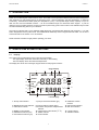
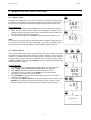
Instruction Manual
CON 510
Bench Conductivity/TDS Meter
68X090820
Rev. 0 11/02
Technology Made Easy ...
Preface
This manual serves to explain the use of the CON 510 bench meter. It functions in two ways, firstly as a step
by step guide to help you to operate the meter. Secondly, it serves as a handy reference guide. It is written to
cover as many anticipated applications of the meter as possible. If there are doubts in the use of the meter,
please do not hesitate to contact the nearest Authorized Distributor.
Eutech Instruments/ Oakton Instruments cannot accept any responsibility for damage or malfunction to the
meter caused by improper use of the instrument.
The information presented in this manual is subject to change without notice as improvements are made,
and does not represent a commitment on the part of Eutech Instruments Pte Ltd/ Oakton Instruments.
Note: Eutech Instruments Pte Ltd/ Oakton Instruments reserves the right to make improvements in design,
construction, and appearance of our products without notice.
Copyright © 2002 All rights reserved.
Eutech Instruments Pte Ltd
Oakton Instruments
Rev. 0 11/02
TABLE OF CONTENTS
1
INTRODUCTION
2
DISPLAY AND KEYPAD FUNCTIONS
1
2.1
2.2
Display
Keypad
1
2
3
PREPARATION
3
3.1
3.2
3.3
3.4
Conductivity Electrode Information
Connecting the probe to the meter
Connecting the AC/DC Adapter
Connecting the Electrode Holder
3
3
3
4
4
CALIBRATION
5
4.1
4.2
4.3
4.4
4.5
4.6
4.7
4.8
Important Information on Meter Calibration
Preparing the Meter for Calibration
Calibration with Conductivity Standards and TDS factor
Calibration for TDS Standards Directly
Selection of Automatic or Manual Calibration
Automatic Calibration
Manual Calibration
Temperature Calibration
5
6
6
6
6
7
8
9
5
MEASUREMENT
10
5.1
5.2
5.3
5.4
5.5
Automatic Temperature Compensation
Manual Temperature Compensation
Taking Measurements
Using Manual Ranging Function
HOLD Function
10
11
11
12
12
6
MEMORY AND DATA INPUT FUNCTIONS
13
6.1
6.2
Memory Input
Memory Recall
13
13
7
SETUP FUNCTIONS
14
7.1
7.2
7.3
7.4
7.5
7.6
7.7
7.8
SETUP Mode Overview
P1.0: Viewing Calibration Data
P2.0: Viewing Electrode Diagnosis
P3.0: Meter Configuration
P4.0: Temperature
P5.0 Mode of calibration
P6.0 Selecting the cell constant
P7.0: Resetting to factory default settings
14
15
16
16
18
20
21
22
8
PROBE CARE AND MAINTENANCE
23
9
TROUBLE SHOOTING GUIDE
24
1
10 ERROR MESSAGES
24
11 SPECIFICATIONS
25
12 ACCESSORIES
26
13 ADDENDUM 1: CALIBRATION TIPS
27
14 ADDENDUM 2: CALCULATING TDS CONVERSION FACTORS
27
15 ADDENDUM 3: CALCULATING TEMPERATURE COEFFICIENTS
28
16 ADDENDUM 4: METER FACTORY DEFAULT SETTINGS
29
17 WARRANTY
30
18 RETURN OF ITEMS
30
Instruction Manual
1
CON 510
INTRODUCTION
Thank you for selecting the CON510 bench meter. This meter is a microprocessor-based instrument that is designed to
offer advanced yet user-friendly features for discerning users - ideal for laboratory and plant applications. It measures
Conductivity, Total Dissolved Solids (TDS) and temperature (oC/oF). It incorporates large memory capacity of up to 50
data sets and user-customisable functions – all are accessible through the membrane tactile keypad. A pull-out
reference card (concealed at bottom of meter) provides a quick handy guide to the functions of the individual keys as well
as useful troubleshooting hints for your reference.
The meter is packaged with a 2-ring Stainless Steel Ultem-body Conductivity/TDS electrode (cell constant K = 1.0) with
built-in temperature sensor (Order Code: EC-CONSEN91W/ 35608-50) and an integral electrode holder. For the list of
accessories refer to the Section 12 on Accessories.
Please read this manual thoroughly before operating your meter.
2
2.1
DISPLAY AND KEYPAD FUNCTIONS
Display
The LCD (Liquid Crystal Display) has an upper and lower display.
The upper display shows the measured conductivity or TDS reading.
The lower display shows the measured temperature.
The display also shows error messages, keypad functions and program functions.
Upper Display
1
SETUP
17
READY
16
HOLD
ON
15
OFF
3
2
CAL
MEAS
4
MEM
-8.8.8.8
K=
O
O
C F
ERR
14
mS
µS
ppt
ppm
5
6
7
8
10
ATC
13
11
12
Lower Display
1. SETup mode indicator
7. parts per thousand indicator (ppt)
2. MEASurement mode indicator
3. CALibration indicator
8. parts per million indicator (ppm)
9. Automatic Temperature Compensation
indicator
10. Temperature scale indicator (oC oF)
11. ERRor indicator
12. Probe indicator
4. MEMory mode indicator
5. millisiemens indicator (mS)
6. microsiemens indicator (µS)
1
9
13. Calibration solution
indicator
14. Cell constant indicator
15. ON / OFF indicator
16. HOLD indicator
17. READY indicator
Instruction Manual
2.2
CON 510
Keypad
The splash-proof membrane tactile keypad allows easy key entry. Each button, when pressed, has a corresponding
graphic icon or indicator displayed on LCD. Some buttons have several functions depending on its mode of operation.
Key
Function
ON/OFF
Powers on and shuts off the meter. When you switch on the meter, the meter starts up in the mode
that you last switched off from. For example, if you shut the meter off in TDS measurement mode,
the meter will be in TDS measurement mode when you switch the meter on.
HOLD
Freezes the measured reading. To activate, press HOLD while in measurement mode. To release,
press HOLD again.
MODE
Selects the measurement parameter. Toggles between conductivity and TDS.
CAL/MEAS
Toggles between Calibration and Measurement mode.
NOTE: Temperature calibration is available from conductivity/TDS calibration mode.
ENTER /
RANGE
ENTER function: Press to confirm values in Calibration mode and to confirm selections in SETUP
mode.
RANGE function: Press to enter manual ranging function.
The MEAS indicator blinks while in manual ranging function.
MI & MR
▼/▲
SETUP
In Measurement mode:
Press MI (memory input) to store values with its corresponding temperature values in the memory.
Press MR (memory recall) to retrieve data from memory (Last-In-First-Out Sequence).
In Calibration mode:
Press to scroll through calibration values.
In SETUP mode:
Press to scroll through the setup subgroup program.
Takes you into the SETUP mode. This mode lets you customize meter preference and defaults, and
view calibration data and select cell constant.
2
Instruction Manual
3
3.1
CON 510
PREPARATION
Conductivity Electrode Information
The CON510 bench meter is supplied with a Conductivity/TDS electrode (with a sturdy locking 6-pin
connector). This Conductivity/TDS electrode (Code No: ECCONSEN91W/ 35608-50) comes with
Stainless Steel rings, cell constant of K = 1.0, and a built-in temperature sensor for Automatic
Temperature Compensation (ATC). Its specially designed Ultem-body housing has good chemicalresistant properties. It provides fast temperature response and reduces air bubble entrapment,
which makes it easy to obtain accurate, stable readings.
The probe materials used which have good chemical durability include:
1. Polyetherimide (Ultem) – protective probe guard
2. Polybutylterphalate (Valox) – sensor housing
3. Stainless Steel (SS 304) – 2 steel bands
Proper use of probe is essential to ensure that the optimum measurement is taken in a short time.
The removable protective plastic probe guard is meant for simple periodic maintenance and it must
be kept in tact during measurement and calibration.
Always immerse the probe beyond upper steel band.
NOTE: DO NOT remove the protective probe guard during measurement and calibration as it may
affect your readings.
NOTE: We recommend that you do not submerge the probe above the protective probe guard. You
can submerge the cable for brief periods of time, but not continuously.
See Section 8 for “Probe Care and Maintenance” information.
3.2
1.
2.
Connecting the Probe to the Meter
Align the notch and 6 pins on the meter with the holes in the 6-pin connector.
Push down and turn the locking ring clockwise to lock into place.
To remove probe, turn the locking ring counterclockwise on probe connector
until it is free. Pull probe gently away from the meter.
CAUTION: DO NOT pull on the probe cord or the probe wires might disconnect.
NOTE: Keep connectors clean. Do not touch connector with soiled hands.
3.3
Connecting the AC/DC Adapter
Slide the AC/DC adapter jack into the socket marked DC of the meter until it is firmly seated. Ensure that the power to
the AC/DC adapter is switched off. For AC/DC adapter always ensure that main voltage matches that of the adapter.
AC/DC adapters used should have the following specifications or settings. Output: - Voltage: 9 VDC Current: 500 mA.
NOTE: Ensure that the input main voltage (110/220 V) matches your adapter requirements before connection.
3
Instruction Manual
3.4
CON 510
Connecting the Electrode Holder
The integral electrode holder serves as a handy holder for
a few electrodes or a separate temperature probe during
measurement or when not in use.
This bench meter’s base plate has a side metal bar to
which you can attach an integral swivel electrode holder.
You can mount the electrode holder on either right or left
side of the meter.
To position the electrode arm:
Use a Phillips screwdriver to remove the screw holding the
electrode holder. Slide the side metal bar until the second
screw slot lines up with the original screw hole. Use the
screw removed earlier to secure the electrode holder into
position. Note the side metal bar is reversible. If desired,
remove screw holding electrode holder base and slide out
of brackets, slide base into brackets on opposite side, and
tighten screw.
Body of
Electrode
Holder
To install the electrode arm to the meter:
To mount the electrode arm into the metal rod on
the side bar, align the slot with the metal rod and
base of electrode arm. Push it downwards until it
fully sits into position. Avoid using excessive force
when fixing or removing. The electrode arm is ready
for use.
Base of
Electrode
Holder
NOTE: Move the base of the electrode holder if you
wish to swing the electrode holder. To prevent the
meter from toppling over causing accidental spills,
DO NOT swing the body of the electrode holder.
Side Metal Bar
4
Instruction Manual
4
CON 510
CALIBRATION
4.1
Important Information on Meter Calibration
The CON 510 bench meter allows you to perform automatic calibration (only for Conductivity mode) or manual calibration
(applicable to both Conductivity/TDS mode). The meter can calibrate either single point or multi-point up to 5 calibration
points (manual mode) with a maximum of 1 point in each measurement range. Use single-point automatic calibration
when calibrating using Conductivity standard calibration solutions (as mentioned in Section 4.6) as it suffices.
When calibrating using uncommon or non-standard Conductivity/TDS calibration solutions which are freshly prepared,
use the manual calibration option as it allows you to manually set to the desired value to match the standards being
used. However if you are measuring sample values in more than one range, it is recommended to calibrate each of the
ranges which you are measuring to ensure best meter accuracy.
•
If you are measuring in ranges near to or greater than 20 mS (10 ppt if TDS factor is set to 0.5), or near to or
lower than 100 µS (50 ppm), calibrate the meter at least once a week to get specified ±1% Full Scale accuracy.
•
If you are measuring in the mid-ranges and you washed the probe in de-ionized water and stored it dry,
calibrate the meter at least once a month.
•
If you take measurements at extreme temperatures, calibrate the meter at least once a week.
For best results, select a standard value close to the sample value you are measuring. Alternatively, use a calibration
solution value that is approximately 2/3 the Full-Scale value of the measurement range you plan to use. For example, in
the 0 to 2000 µS/cm conductivity range, a 1413 µS/cm solution is a good solution for calibration.
The following table lists all the corresponding conductivity and TDS ranges. You should calibrate each range using a
suitable standards solution that falls between the values in the “recommended calibration solution range” column.
Conductivity
Range
Recommended
Calibration Solution
Range
TDS
Range
Recommended
Calibration Solution
Range
r1
0 – 20.00 µS/cm
6.00 - 17.00 µS/cm
0 – 10.00 ppm
3.00 - 8.50 ppm
r2
0 – 200.0 µS/cm
60.0 - 170.0 µS/cm
0 – 100.0 ppm
30.0 - 85.0 ppm
r3
0 – 2000 µS/cm
600 - 1700 µS/cm
0 - 1000 ppm
300 - 850 ppm
r4
0 – 20.00 mS/cm
6.00 - 17.00 mS/cm
0 – 10.00 ppt
3.00 - 8.50 ppt
r5
0 – 200.0 mS/cm
60.0 - 170.0 mS/cm
0 - 100 ppt
30.0 – 85.0 ppt
Range
Indicator
When you recalibrate your meter, old calibration values are replaced on that specific measurement range. For example,
if you previously calibrated the meter at 1413 µS/cm in the 0 - 2000 µS/cm range and you recalibrate at 1500 µS/cm (in
the same range of 0 - 2000 µS/cm), the meter will replace old calibration data (1413 µS/cm) in that range if the meter is
in the multi-point calibration mode and the meter will retain all calibration data in other ranges. Or else, the calibration
data replaces with new data for all ranges (in single-point calibration mode).
To view calibrated solutions and its corresponding cell constants at respective range, see SETUP main-menus P1.0 and
P2.0.
To completely recalibrate your meter, or when you use a replacement probe, it is best to clear all the calibration data in
the meter’s memory. To erase all the old conductivity and TDS calibration data completely from memory, see SETUP
main-menu P7.0.
Temperature Coefficient: This meter is factory set to a temperature coefficient of 2.1 % per °C. For most applications
this will provide good results. See SETUP sub-menu P4.1 to set the temperature coefficient to different value. See also
Addendum 2, “Calculating Temperature Coefficients” to determine the appropriate temperature coefficient for your
solution.
5
Instruction Manual
CON 510
Normalization Temperature: The factory default value for normalization temperature is 25 °C. If you need to normalize
to a value other than 25 °C, see SETUP sub-menu P4.2.
4.2
Preparing the Meter for Calibration
Before starting calibration, make sure you are in the correct measurement mode. Otherwise press MODE key to toggle
between measurement modes. When you switch on the meter, it starts up in the last unit of measure when you last shut
off the meter.
DO NOT reuse calibration solutions after each calibration has been performed. Contaminants in the solution can affect
the calibration, and eventually the accuracy of the measurements. Use fresh calibration solution each time you calibrate
your meter. Always remember to rinse thoroughly with de-ionized water or a rinse solution after each calibration to
prevent any carry-over.
NOTE: When entering calibration mode, the meter will display the uncalibrated value.
To abort or exit from any calibration mode or SETUP options without confirming any set values, DO NOT press
the ENTER key. Press CAL/MEAS instead. This will retain the meter’s old calibration data in the specific measurement
range or previous SETUP options.
4.3
Calibration with Conductivity Standards and TDS factor
The concentration of salts dissolved in solution increases the conductivity of that solution. This relationship varies from
salt to salt and is roughly linear over a given range for a given salt. The TDS conversion factor is the number used by the
meter to convert from conductivity to TDS. Default is 0.50; allowed window is 0.40 to 1.00.
Instead of calibrating for TDS directly, you can calibrate the CON 510 bench meter by:
1. calibrating to conductivity standards and then
2. entering the appropriate TDS conversion factor into the meter.
To determine the conductivity to TDS conversion factor for your solution:
Addendum 2 lists some commonly used conversion factors.
Addendum 3 describes how to calculate the TDS conversion factor for other solutions.
Enter the TDS conversion factor into your meter as described under SETUP sub-menu P3.4.
4.4
Calibration for TDS Standards Directly
The factory default setting for TDS conversion factor is 0.50. If your solution has a different TDS factor, you can improve
the calibration accuracy by setting the correct TDS factor (0.40 to 1.00) prior to calibration in SETUP sub-menu P3.4.
4.5
Selection of Automatic or Manual Calibration
This meter is capable of performing either automatic for Conductivity measurement mode or manual calibration method
for both Conductivity and TDS measurement modes. In the automatic calibration mode, the meter automatically detects
and verifies the appropriate known calibration standards solutions being calibrated before accepting these particular
calibration standards as one of its calibration values in a specific measurement range. This automatic calibration mode
frees you from cumbersome calibration procedure. While in the manual calibration, non-standards calibration values can
be used for calibration, in which you can manually input the appropriate values as your desired calibration standards in
each specific range.
Proceed to SETUP main-menu P5.0 to select the type of calibration method before performing calibration.
6
Instruction Manual
4.6
CON 510
Automatic Calibration (Only for Conductivity)
In the automatic calibration mode, the CON 510 bench meter is capable of accepting either single-point or up to 4 points
for multi-point calibration with maximum of 1 point per specific measurement range using known calibration standards
values which include: 84 µS/cm (0 – 200.0 µS/cm), 1413 µS/cm (0 – 2000 µS/cm), 12.88 mS/cm (0 – 20.00 mS/cm) and
111.8 mS/cm (0 – 200.0 mS/cm).
NOTE: You need to set your desired option i.e. number of calibration points in the SETUP main-menu P5.0 before
performing calibration.
MODE
4.6.1
1.
2.
3.
4.
5.
6.
7.
8.
Conductivity Automatic Calibration
If necessary, press the MODE key to select conductivity mode.
Rinse the probe thoroughly with de-ionized water or a rinse solution, then rinse with
a small amount of calibration standard.
Dip the probe into the calibration standard. Immerse the probe tip beyond the upper
steel band. Stir the probe gently to create a homogeneous sample. Allow time for
the reading to stabilize.
Press CAL/MEAS to enter conductivity calibration mode. The [CAL] indicator will
appear in the upper right corner of the display.
The lower display will scan and lock the closest set calibration values momentarily.
Pressing before the set displayed value being locked will be prompted by an error
message and remain in the calibration mode.
Wait for [READY] indicator to appear before pressing ENTER key to confirm
calibration value. The upper display will show “dOnE” once the calibration is
successfully performed. The meter returns to the [MEAS] measurement mode.
To abort calibration without confirming, press CAL/MEAS to revert back to
measurement mode. No calibration is performed at this stage.
To perform the next point calibration in the multi-point calibration, repeat step 1-7
again until all points have been calibrated if necessary.
MEAS
READY
uS
.
o
C
ATC
CAL
MEAS
CAL
READY
uS
ENTER
RANGE
CAL
MEAS
MEAS
READY
uS
.
7
o
C
ATC
Instruction Manual
4.7
CON 510
Manual Calibration (Conductivity/TDS)
The meter accepts either single point or multi-point (up to 5 points) manual calibration
with maximum of 1 point per measurement range. Freshly prepare your standards
solution before calibration. Refer to the table in Section 4.1 for more details of the
recommended standards calibration range.
MODE
MEAS
READY
uS
.
You can offset or manually adjust the Conductivity or TDS reading up to ±40% from its
default setting. If your measured value differs by more than ±40%, clean or replace probe
as needed. Refer to Section 8 for Probe Maintenance.
o
C
ATC
CAL
NOTE: You need to set your desired option i.e. number of calibration points in the
SETUP main-menu P5.0 before performing calibration.
MEAS
CAL
uS
4.7.1
Conductivity Manual Calibration
1.
2.
If necessary, press the MODE key to select conductivity mode.
Rinse the probe thoroughly with de-ionized water or a rinse solution, and rinse with a
small amount of calibration standard.
3. Dip the probe into the calibration standard. Immerse the probe tip beyond the upper
steel band. Stir the probe gently to create a homogeneous sample. Allow time for the
reading to stabilize.
4. Press CAL/MEAS key to enter conductivity calibration mode. The [CAL] indicator
will appear in the upper right corner of the display.
5. Use MI/▲ or MR/▼ key to adjust the value on the upper display to match the value
of the calibration standards.
6. Press ENTER to confirm calibration value. The meter returns to the [MEAS]
measurement mode.
7. To abort calibration without confirming, press CAL/MEAS key to revert back to
measurement mode. No calibration is performed at this stage.
9. For single-point calibration the meter automatically reverts back to the measurement
mode.
10. For multi-point calibration repeat steps 2 to 6 for the second to fifth calibration value
in specific measuring ranges. To abort calibration at any calibration points, press
CAL/MEAS once and the meter reverts to measurement mode.
4.7.2
ENTER
RANGE
CAL
uS
CAL
MEAS
MEAS
READY
uS
.
o
C
ATC
TDS Manual Calibration
The calibration sequence is exactly the same as Conductivity manual calibration. Ensure that you set the correct TDS
factor before calibration. Refer to Section 7.4 for details.
8
Instruction Manual
4.8
CON 510
Temperature Calibration
The Conductivity electrode (EC-CONSEN91W/ 35608-50) has a built-in temperature
sensor for ATC. The temperature sensor is factory calibrated to the meter. Calibrate
your sensor only if you suspect temperature errors that may have occurred over a long
period of time or if you have a replacement probe.
Temperature Calibration
1. Make sure the electrode is attached to the 6-pin connector.
2. Power the meter on. The [ATC] indicator will appear at the right-hand side of the
LCD to indicate that the temperature sensor is in good working condition. If the ATC
indicator does not light up, see SETUP sub-menu P3.3 to switch it on.
3. Press MODE key to select either conductivity or TDS mode.
4. Press CAL/MEAS to enter either Conductivity or TDS calibration mode. The [CAL]
indicator appears above the upper display.
5. While you are in the Conductivity or TDS calibration mode, press MODE to enter
into Temperature calibration mode. The upper display shows current temperature
reading and the lower display shows the factory default temperature value.
6. Dip the electrode into a solution of known temperature (i.e. a constant temperature
bath). Allow about 3 to 5 minutes for the built-in temperature sensor to stabilize its
measured reading.
7. Adjust using the MI/▲ or MR/▼ key to set to the correct temperature value (i.e. the
temperature of the constant temperature bath) in increments of 0.1 °C. Maximum
allowable offset temperature value is 5.0 °C.
8. Once you have selected the correct temperature, press ENTER key. To abort or exit
this calibration mode without confirming the temperature calibration value, DO NOT
press ENTER key. Press CAL/MEAS key instead and the meter automatically
reverts back to the measurement mode.
MODE
CAL
MEAS
CAL
uS
.
o
C
ATC
MODE
CAL
.
.
o
C
ATC
ENTER
RANGE
CAL
.
.
o
C
CAL
MEAS
MEAS
READY
uS
.
9
o
C
ATC
Instruction Manual
5
CON 510
MEASUREMENT
The CON 510 bench meter measures up to 5 different measurement ranges with auto-ranging capability which
automatically detects and promptly switches to the appropriate range. The meter also allows measurements to be taken
with automatic or manual temperature compensation. The factory default is ATC on.
ATC basically compensates for any temperature variances of measured sample solution temperature automatically from
the normalization temperature set. Default normalization temperature is 25.0 °C (77.0 °F). However if you need to adjust
the default value from 15.0 to 30.0 °C, you may access SETUP sub-menu P3.4 first before measurement.
5.1
SETUP
Automatic Temperature Compensation
For automatic temperature compensation (ATC) simply plug the conductivity/TDS probe
into the meter. The [ATC] indicator will light on the LCD. Default is ATC “YES”.
.
NOTE: If the ATC indicator does not light up, manual temperature compensation may be
set in the SETUP sub-menu P3.3. See SETUP sub-menu P3.3 for directions on selecting
ATC or MTC.
o
C
ATC
SETUP
To select option either ATC “YES” or “nO”, use either MI/▲ or MR/▼ key. Press ENTER
to confirm. Otherwise press CAL/MEAS key to abort option selection.
o
C
ATC
SETUP
o
C
ENTER
RANGE
10
OR
CAL
MEAS
Instruction Manual
5.2
CON 510
Manual Temperature Compensation
NOTE: For manual temperature compensation, you must deactivate the ATC mode to ‘nO’ as shown in SETUP submenu P3.3.
5.2.1
Setting a manual temperature compensation value
To set manual temperature compensation value, you need to determine and enter the
desired temperature value into the meter. This value is based on which reading will be
manually temperature compensated. You may select any temperature between 0 and 100
°C (32 to 212 °F). Default value is 25.0 °C.
1.
2.
3.
4.
5.
6.
7.
MODE
CAL
.
Switch the meter on if necessary. Press MODE to select any measurement mode.
If necessary, select ATC to OFF as described in Section 5.1. Note the [ATC] indicator
should not appear on the display.
Press CAL/MEAS to enter into either conductivity or TDS calibration mode. The
[CAL] indicator will appear above the upper display.
While in Conductivity or TDS calibration mode, press MODE key to enter into
temperature calibration mode. The upper display shows the current temperature
setting and the lower display shows the default value 25.0 °C (77.0 °F) or its last set
temperature value.
Check the temperature of your sample solution using an accurate thermometer.
Use MI/▲ or MR/▼ key to offset and match the temperature to the measured value
of the sample solution.
Press ENTER key to confirm the set temperature value and the meter returns to the
conductivity or TDS measurement mode.
.
CAL
MEAS
o
MODE
CAL
.
.
o
READY
5.3
C
ATC
MEAS
The meter will now display your newly set temperature value in the lower display and will
compensate Conductivity or TDS readings accordingly based on this set temperature.
NOTE: To exit this program without confirming the manual temperature compensation
value, DO NOT press ENTER key in step 7. Press CAL/MEAS key instead and note that
no change is being made at this stage.
C
ATC
uS
.
o
C
ENTER
RANGE
Taking Measurements
To take readings:
1. Always rinse the probe with de-ionized or distilled water before use and after each sample to remove any impurities
adhering to the probe body. Shake or air dry. To avoid contamination or dilution of your sample, rinse probe with a
small volume of your sample solution.
2. Press ON to switch on the meter and the [MEAS] indicator appears on the top of the LCD.
3. Dip the probe into the sample. Ensure that the solution level is above its upper steel band. Stir the probe gently in
the sample to create a homogenous sample.
4. Allow time for the reading to stabilize. Note the reading on the display.
5. Press MODE to toggle between Conductivity and TDS measurement.
Taking measurements with READY indicator selected on
If the READY indicator has been activated, the [READY] indicator lights whenever the reading has stabilized. You may
switch the READY indicator on or off by following the sequence as described in SETUP sub-menu P3.1.
Taking measurements with the Auto-Hold feature selected on
When a reading has stabilized for more than 5 seconds, the Auto-Hold feature automatically “freezes” the displayed
reading and the [HOLD] indicator appears. Press HOLD once to release the reading. You may deactivate the Auto-Hold
feature as described in SETUP sub-menu P3.1.
11
Instruction Manual
5.4
CON 510
Using Manual Ranging Function
Although the CON 510 bench meter has an automatic ranging capability, you may also
manually select any specific measurement range you wish to work on by pressing
RANGE each time for every range.
ENTER
RANGE
MEAS
READY
Range
Indicator
Conductivity
Range
uS
TDS Range
(if TDS factor is 0.5)
r1
0 – 20.00 µS/cm
0 – 10.00 ppm
r2
0 – 200.0 µS/cm
0 – 100.0 ppm
r3
0 – 2000 µS/cm
0 – 1000 ppm
r4
0 – 20.00 mS/cm
0 – 10.00 ppt
r5
0 – 200.0 mS/cm
0 – 100 ppt
.
C
o
ATC
ENTER
RANGE
MEAS
uS
C
o
1.
2.
3.
To manually select the desired measuring range, press RANGE key while you are
in the measurement mode. The first range will appear on the display and the
[MEAS] indicator blinks.
Press RANGE key again (if needed) until the desired range is selected.
To re-select the Auto-ranging function, repeatedly press RANGE key until the
[MEAS] indicator appears without blinking. The display will then scroll through the
various ranges and the Auto-ranging function resumes. Or simply power off and on
again will restart meter into Auto-ranging function as default.
ATC
ENTER
RANGE
MEAS
uS
READY
.
C
o
ATC
NOTES: If the value of the solution you are measuring is higher than the range
selected, an error message code “Or” will appear on the upper display indicating an
over-range condition. Press RANGE key until the correct range is selected. However the
meter reverts back to the Auto-ranging function once it is powered off.
5.5
HOLD Function
HOLD
This feature allows you to freeze the displayed reading momentarily when activated in
the measurement mode and the [HOLD] indicator appears on the LCD. To release the
held value, press HOLD again and the [HOLD] indicator disappears. You may continue
to take measurements.
12
MEAS
READY
HOLD
uS
.
o
C
ATC
Instruction Manual
6
6.1
CON 510
MEMORY AND DATA INPUT FUNCTIONS
Memory Input
The meter’s non-volatile memory can store and recall up to 50 data sets which include
Conductivity and temperature or TDS and temperature. Data sets are retained even if
the power is shut off unless these stored data sets are being overwritten by new ones.
MEAS
READY
uS
.
To store a reading:
1. During any measurement mode press MI/▲ key to input any data into the memory.
2. MEM, “Sto” and memory location number will be displayed to indicate that the
readings are being stored into meter’s memory at that specific location number. The
meter then returns to the measurement mode.
3. To continue storing data sets, press MI/▲ to input subsequent data into memory.
o
C
ATC
MEM
NOTE:
If the memory is full, the first data set value stored will be overwritten to create space for
the new value. Data sets are stored sequentially in the next unoccupied memory
location and cannot be selectively input into specific memory location to be stored.
6.2
ENTER
Memory Recall
RANGE
You can access memory recall from any measurement mode only. This function recalls
and displays previous readings being stored in the meter’s memory in “Last-In-First-Out"
sequence. For example the most recent reading stored in location 20 will be displayed
first when memory recall is activated. To selectively view any specific memory location,
use MI/▲ or MR/▼ to select and press ENTER to view the corresponding data set value
stored in that memory location.
MEM
CAL
To recall readings:
1. Press MR/▼ key once to retrieve the last reading stored. The memory location
screen – MEM, “Loc” and the memory number will flash on the display.
2. Press ENTER to recall the reading stored under that memory number.
3. To view the next memory location, press ENTER key once and the display
automatically moves to the next memory location.
4. Press CAL/MEAS key to revert back to measurement mode if you do not wish to
access memory recall further.
5. If necessary, press MI/▲ or MR/▼ key to select any specific memory location. Press
ENTER key to view the stored values in that memory location. If there is no data
stored in particular memory location, both upper and lower displays will show “----“.
MEAS
MEM
uS
.
MEM
ENTER
RANGE
MEM
13
o
C
ATC
Instruction Manual
7
CON 510
SETUP FUNCTIONS
The setup mode allows you to customize the meter’s setting to your individual preferences. The CON510 meter features
different main program menus and sub-menus which organize individual parameters like a matrix-format.
Details of each main program menu:
1. P1.0:
Viewing previous calibration data - all calibrated solutions for each range
2.
P2.0:
Viewing electrode diagnosis - effective cell constants for each range
3.
P3.0:
Meter configuration – Ready, Auto-Hold, Temperature unit of measure, ATC or MTC, TDS Factor
4.
P4.0:
Setting of Temperature Coefficient, Normalization Temperature
5.
P5.0:
Setting of Automatic or Manual and Single or Multi-point calibration
6.
P6.0:
Setting of cell constant
7.
P7.0:
Resetting meter to factory defaults
7.1
SETUP Mode Overview
Press SETUP to enter into the setup mode with [SETUP] indicator on the top left of LCD display. Use the MI/▲ and
MR/▼ keys to scroll up and down respectively through main menus. At each main menu, press ENTER to enter into a
particular sub-menu to make specific changes from the meter’s default settings. See Addendum 4 for a table of meter
factory default settings.
SETUP
.
P1.0: Viewing Previous Calibration Data
P1.1 First range calibration solution
P1.2 Second range calibration solution
P1.3 Third range calibration solution
P1.4 Fourth range calibration solution
P1.5 Fifth range calibration solution
.
P2.0: Viewing Calibrated Cell Constants
P2.1 Effective cell constant for first range
P2.2 Effective cell constant for second range
P2.3 Effective cell constant for third range
P2.4 Effective cell constant for fourth range
P2.5 Effective cell constant for fifth range
SETUP
SETUP
.
P3.0: Meter Configuration
P3.1 READY indicator On/Off and Auto-Hold On
P3.2 Select °C or °F
P3.3 Select Automatic or Manual Temperature Compensation
P3.4 Setting TDS conversion factor (available in TDS mode)
P4.0: Temperature
P4.1 Adjusting temperature coefficient
P4.2 Adjusting normalization temperature
SETUP
.
14
Instruction Manual
CON 510
SETUP
.
P5.0: Mode of Calibration
Selection of Automatic or Manual Calibration
(only in Conductivity mode)
Selection of Single or Multi-point Calibration
P6.0: Selecting cell constant
Selecting cell constant K: 0.1, 1.0, 10.0
SETUP
.
P7.0: Reset to factory defaults
Reset meter to factory defaults
SETUP
.
7.2
SETUP
P1.0: Viewing Calibration Data
CAL
This mode lets you recall previous calibration data of Conductivity/TDS. This is for
viewing only and no changes can be made.
1.
2.
3.
4.
From measurement mode, press SETUP key to enter into setup [SETUP] mode.
Use MI/▲ or MR/▼ to scroll through sub-menus until you view main-menu CAL
P1.0 on the display.
Press ENTER repeatedly to view all previous calibration data, starting from the first
range till fifth range. The meter will display the calibration value of that particular
range provided calibration is performed. If any of range is not being calibrated the
upper display shows “---“.
When you have scrolled through all calibration data, you will automatically return to
the SETUP main-menu P1.0. Press CAL/MEAS key if you wish to return to
measurement [MEAS] mode. Or to exit from viewing of any range in respective submenus, press CAL/MEAS key reverts to the SETUP main-menu P1.0.
NOTE: If you enter into the setup mode from Conductivity measurement mode,
calibration data will be in µS or mS. Similarly if you enter into the setup mode from TDS
measurement mode, calibration data will be in ppm or ppt.
.
ENTER
RANGE
SETUP
CAL
.
SETUP
CAL
uS
.
CAL
MEAS
SETUP
CAL
uS
.
CAL
MEAS
15
Instruction Manual
7.3
CON 510
P2.0: Viewing Electrode Diagnosis
Main program 2.0 shows the effective cell constant for each range being calibrated. The
cell constant is adjusted according to your calibration options that let you check the
probe’s parameters for diagnostic purposes.
1.
2.
3.
4.
From measurement mode, press SETUP key to enter into setup [SETUP] mode.
Use MI/▲ or MR/▼ key to scroll through sub-menus until you view main-menu ELE
P2.0 on the display.
Press the ENTER key repeatedly to view the effective cell constant for each range.
When you have scrolled through all calibration data, you will automatically return to
the SETUP main-menu P2.0. Press CAL/MEAS key if you wish to return to
measurement [MEAS] mode.
NOTE: Cell constants of electrode will degrade with time and usage depending on your
maintenance and wear and tear of the electrode being used. You can use this feature to
prompt you the need for a new probe prior to total failure. Recommended value as an
indicator for a replacement of probe is either 0.60 or 1.40 (±40% of 1.000).
SETUP
.
ENTER
RANGE
SETUP
K=
.
CAL
MEAS
SETUP
K=
7.4
.
.
.
P3.0: Meter Configuration
P3.1: READY indicator and Auto-Hold function
Program P3.1 allows you to select “READY ON”, “READY OFF” and activate the AutoHold function. “READY” indicator is a useful feature that prompts you whenever your
measured reading has stabilized. Once activated you will see [READY] indicator lights
up whenever your readings have stabilized. At this moment, you may depress MI/▲ to
store the reading into meter’s memory.
Select “READY OFF” for instantaneous measurement with no [READY] indicator being
lighted up on the display.
SETUP
.
ENTER
RANGE
SETUP
You may activate the Auto-Hold function which automatically freezes measured reading
after it has stabilized for more than 5 seconds. Once the display is frozen, the [HOLD]
indicator appears on the display. At this moment, you may depress MI/▲ to store the
reading into meter’s memory. Press HOLD once to release the held reading and to
access other functions in the measurement mode. You may deactivate this feature by
selecting either “READY ON/OFF”.
1.
2.
3.
4.
5.
From measurement mode, press SETUP key to enter into setup [SETUP] mode.
Use MI/▲ or MR/▼ key to scroll through the sub-menus until you view SETUP
main-menu P3.0 on the display.
Press ENTER key to select sub-menu P3.1 with upper display showing “rdY”.
Use MI/▲ or MR/▼ key to select the appropriate configuration you require.
Selecting ON switches the READY indicator on; OFF switches the READY indicator
off; ON and HOLD together switches the Auto-Hold feature on.
Press ENTER to confirm selection and to proceed to Program P3.2. If you do not
wish to continue P3.2, press CAL/MEAS to return back to the measurement [MEAS]
mode.
READY
ON
.
SETUP
READY
OFF
.
ENTER
RANGE
SETUP
READY
HOLD
ON
.
CAL
MEAS
16
Instruction Manual
CON 510
P3.2 Selecting °C or °F
You can select between °C and °F as unit of measure for temperature readings. Meter
default is °C.
ENTER
RANGE
SETUP
1.
2.
3.
4.
From measurement mode, press SETUP key to enter into Setup [SETUP] mode.
Use MI/▲ or MR/▼ key to scroll through the SETUP main-menu P3.0 and press
ENTER until you can view sub-menu P3.2 on the display.
Use MI/▲ or MR/▼ key to toggle between °C and °F.
Press ENTER to confirm selection and you will automatically return to the SETUP
main-menu P3.0. Press CAL/MEAS key if you wish to return to measurement
[MEAS] mode.
.
o
C
ENTER
RANGE
SETUP
NOTE: Similarly if you are accessing SETUP main-menu P3.0, pressing ENTER twice
will take you to this SETUP sub-menu P3.2.
.
o
F
CAL
MEAS
P3.3 Selecting Automatic or Manual Temperature Compensation
This Program P5.3 allows you select between Automatic Temperature Compensation
(ATC) and Manual Temperature Compensation. Meter default is ATC.
1.
2.
3.
4.
5.
From measurement mode, press SETUP key to enter into setup [SETUP] mode.
Use MI/▲ or MR/▼ key to scroll through the main-menus “COF P3.0” and press
ENTER key repeatedly until you come to the SETUP sub-menu P3.3 which the
upper display shows “ATC” and “P3.3” on the lower display.
Press ENTER key again. The upper display shows “ATC” and the lower display
shows “YES” or “NO”.
Use MI/▲ or MR/▼ key to select the Automatic Temperature Compensation on or
off. YES = ATC on; NO = ATC off
Press ENTER key to confirm selection and to return to the SETUP sub-menu P3.3.
Press CAL/MEAS key to return to measurement [MEAS] mode.
ENTER
RANGE
SETUP
.
o
C
ATC
ENTER
RANGE
SETUP
o
C
ATC
ENTER
RANGE
SETUP
o
C
CAL
MEAS
17
Instruction Manual
CON 510
P3.4 Setting the TDS factor (In TDS Mode)
The concentration of salts dissolved in solution increases the conductivity of that
solution. This relationship varies from salt to salt and is roughly linear over a given range
for a given salt. The TDS conversion factor is the number used by the meter to convert
from conductivity to TDS.
ENTER
RANGE
SETUP
ppt
ppm
To determine the conductivity to TDS conversion factor for your solution:
Addendum 2 lists some commonly used conversion factors.
Addendum 3 describes how to calculate the appropriate TDS conversion factor for other
solutions. You can manually set TDS conversion factor between 0.40 and 1.00; meter’s
default is 0.50.
1.
2.
3.
4.
5.
7.5
From measurement mode, press SETUP key to enter into setup [SETUP] mode.
Use MI/▲ or MR/▼ key to scroll through the SETUP main-menus “COF P3.0” and
press ENTER key repeatedly until you come to the sub-menu Program P3.4 which
the upper display shows “tds” and “P3.4” on the lower display.
Press the ENTER key again to make changes to the displayed value. The upper
display shows a value and the lower display shows “tdS”.
Use MI/▲ or MR/▼ key to set your calculated TDS conversion factor.
Press the ENTER key to confirm selection and to return to the SETUP sub-menu
P3.0. Press CAL/MEAS key to return to measurement [MEAS] mode.
3.
4.
5.
ENTER
RANGE
SETUP
.
ppt
ppm
CAL
MEAS
ENTER
P4.0: Temperature
RANGE
P4.1 Adjusting the Temperature Coefficient
The temperature coefficient is the amount of change in conductivity per degree of
temperature; it is expressed in percent per °C or °F. Entering the exact temperature
coefficient of your solution lets you accurately compensate temperature for almost any
solution*. You can adjust 0.0 to 10.0 % per °C or °F. Meter default is 2.1% per °C or °F.
1.
2.
.
From measurement mode, press SETUP key to enter into setup [SETUP] mode.
Use MI/▲ or MR/▼ key to scroll through the SETUP main-menu “tPr P4.0” and
press ENTER until you can view sub-menu P4.1.
Press ENTER key to make change to the displayed value. The upper display
shows the temperature coefficient and the lower display shows “t.CO”.
Press MI/▲ or MR/▼ key to set the temperature coefficient of your solution.
Press ENTER to confirm selection and to proceed to SETUP sub-menu P4.2.
Press CAL/MEAS key twice to return to measurement [MEAS] mode.
NOTE: If you do not know the temperature coefficient of your solution you can
determine the correct value using the formula in Addendum 3 “Calculating Temperature
Coefficients”.
SETUP
.
o
CF
ENTER
RANGE
SETUP
.
.
SETUP
.
CAL
MEAS
18
o
.
o
o
C F
Instruction Manual
CON 510
P4.2 Adjusting the Normalization Temperature
Your meter will normalize its conductivity measurements to a standard temperature that
you can select. You can adjust the normalization temperature from 15 to 30 °C (59 to
86 °F). Meter default is 25.0 °C (77 °F).
1.
2.
3.
4.
5.
From measurement mode, press SETUP to enter into setup [SETUP] mode.
Use MI/▲ or MR/▼ key to scroll through the SETUP main-menu P4.0 and press
ENTER thrice repeatedly until you can view the sub-menu P4.2 which the upper
display shows “t.nr” on and “P4.2” on the lower display.
Press ENTER key to make change to the displayed value. The upper display
shows the normalization temperature and the lower display shows “t.nr”.
Press MI/▲ or MR/▼ key to set the normalization temperature (in the specific unit
of temperature which is set at SETUP sub-menu P3.2).
Press ENTER to confirm selection and to return to the SETUP main-menu P4.0.
Press CAL/MEAS key to return to measurement [MEAS] mode.
ENTER
RANGE
SETUP
.
C oF
ENTER
RANGE
SETUP
.
.
.
CAL
MEAS
19
o
.
o
C oF
o
C
Instruction Manual
7.6
CON 510
P5.0 Mode of calibration
The CON 510 bench meter allows you to perform automatic (only for Conductivity
mode) or manual calibration (applicable to both Conductivity/TDS mode). Similarly you
may choose to perform either single-point or multi-point calibration (up to 4 preset
calibration standards in automatic calibration mode). Refer to the Section 4 for details
on calibration.
1.
2.
3.
4.
5.
6.
From measurement mode, press SETUP to enter into setup [SETUP] mode.
Use MI/▲ or MR/▼ key to scroll through main-menu “ACAL P5.0”.
Press ENTER key to enter into this main-menu for selection of Automatic
Calibration either “nO” (Manual) or “YES” (Automatic) using MI/▲ or MR/▼ key.
Once the option is selected, press ENTER key to confirm. The next display shows
the option of Single-point Calibration (SPC) or Multi-point Calibration.
Use MI/▲ or MR/▼ key to select “YES” if you wish to perform Single-point
Calibration and “nO” to perform Multi-point Calibration.
Press ENTER key to confirm after appropriate selection is made and to return to
the SETUP main-menu P5.0. Press CAL/MEAS key to return to measurement
[MEAS] mode.
SETUP
.
ENTER
RANGE
SETUP
ENTER
RANGE
SETUP
SETUP
ENTER
RANGE
SETUP
CAL
MEAS
20
Instruction Manual
7.7
CON 510
P6.0 Selecting the cell constant
This program allows you to select the appropriate cell constant of K = 0.1, 1.0 or 10.0
which is suitable for measurement range being used.
Use a cell of K = 1.0 for mid-range measurements
Use a cell of K = 10 for high range measurements (above 20 mS or 10 ppt).
Use a cell of K = 0.1 for low range measurements (below 20 µS or 10 ppm).
The cell included with your meter has a cell constant of K = 1.0.
1.
2.
3.
4.
From measurement mode, press SETUP key to enter into setup [SETUP] mode.
Use MI/▲ or MR/▼ key to scroll through the main-menu “CELL P6.0” and press
ENTER key to enter into the selection options for the cell constant.
Use MI/▲ or MR/▼ key to select the cell constant between K = 1.0, 0.1, or 10.
Press ENTER key to confirm selection and to return to the main-menu. Press
CAL/MEAS key to return to measurement [MEAS] mode.
NOTES:
When using a cell of K = 0.1, the lowest measuring range will be 0 to 20.00 µS/cm (0 to
10.00 ppm). The 0 to 200.0 mS/cm (0 to 100 ppt) range will not be accessible.
When using a cell of K = 10, the highest measuring range will be 0 to 2000 mS/cm (0 to
2000 ppt). The 0 to 20.00 µS/cm (0 to 10.00 ppm) range will not be accessible.
SETUP
.
ENTER
RANGE
SETUP
K=
SETUP
K=
.
.
.
.
ENTER
RANGE
SETUP
K=
CAL
MEAS
21
.
.
Instruction Manual
7.8
CON 510
P7.0: Resetting to factory default settings
ENTER
RANGE
Program 7.0 allows you to reset all parameters to factory default settings. This clears all
calibration data, memory, and any other setup functions you might have changed.
IMPORTANT: Once activated the meter’s settings and calibration data will be erased
and always exercise caution as meter reset is not reversible.
1.
2.
3.
4.
From measurement mode, press SETUP key to enter into setup [SETUP] mode.
Use MI/▲ or MR/▼ key to scroll through the main-menu “rSt P7.0” and press
ENTER key to enter into the selection options for the meter reset.
Use MI/▲ or MR/▼ key to toggle between NO and YES.
NO retains current settings; YES resets to factory default settings.
Press ENTER key to confirm selection and to return to the measurement mode.
Otherwise press CAL/MEAS key to return to measurement [MEAS] mode without
resetting to factory default.
SETUP
.
SETUP
NOTE: See Addendum 4 for a table of factory default settings.
ENTER
RANGE
SETUP
CAL
MEAS
22
Instruction Manual
8
CON 510
PROBE CARE AND MAINTENANCE
Keep the Conductivity/TDS probe clean. Rinse the probe twice, and gently swirl it while you
take readings. For best accuracy, soak a dry probe for at least 5 to 10 minutes or longer
before calibration. Rinse probe with deionized or tap water before storing. Never scratch the
bands with a hard substance. Do not strike the probe against any hard surface.
Do not make continuous contact with your solutions. Readings will rise over a period of time
while you soak your probe.
Do not immerse the probe in oily solutions. Clean the electrode thoroughly by stirring it in a
mild detergent bath or isopropyl alcohol. Wipe the probe with a soft tissue paper. Rinse
thoroughly in tap water and then in deionized water. Recalibrate the meter after cleaning the
probe.
The conductivity probe (Order Part No. EC-CONSEN91W/ 35608-50) which is included with
your meter features a removable probe guard to make cleaning easy.
To remove probe guard:
1. Grip yellow probe guard and twist clockwise. The locking notch will release.
2. Slide probe guard off end of probe.
23
Instruction Manual
9
CON 510
TROUBLE SHOOTING GUIDE
Problem
No display
Unstable readings
“Or” on upper display
Not able to calibrate
Possible Cause
Solution
A. AC outlet not switched on.
A. Switch on power supply.
B. AC adapter socket not inserted
properly
B. Re-insert AC adapter socket.
A. Air bubbles in probe
A. Tap probe to dislodge air bubbles.
B. Dirty probe
B. Clean probe and recalibrate.
C. External noise pickup
C. Move away from noise.
D. Broken probe
D. Replace probe.
A. Probe is shorted.
A. Test probe.
B. Probe is in too-high solution for
measurement range.
B. Use different solution or select different
range.
A. Dirty/Oily probe
A. Clean
B. Incorrect probe cell constant
B. Replace and use correct probe.
10 ERROR MESSAGES
LCD Display
Indicates
Possible Cause
Solution
Err. annunciator
Unrecognised key entry
Incorrect key entry or
selection
Release key. Check mode.
Select appropriate key.
CAL & Err
annunicator blink
Calibration error
Incorrect value input
during calibration. Dirty
or faulty probe.
Check value. Clean or replace
probe.
24
Instruction Manual
CON 510
11 SPECIFICATIONS
SPECIFICATIONS
Conductivity Range
CON510
0 to 20.00, 200.0, 2000 µS/cm; 0 to 20.00, 200.0 mS/cm
TDS Range
0 to 10.00, 100.0, 1000 ppm; 0 to 10.00, 100.0, 100 ppt
(max. 200 ppt depending on factor setting)
Resolution
0.05 % Full Scale
Accuracy
±1% Full Scale or + 1 digit
0.0 to 100.0 °C; 32.0 to 212 °F
Temperature Range
Resolution / Accuracy
0.1 ° / ± 0.3°C or ± 0.5°F
Cell Constant
0.1, 1.0, 10.0 (selectable)
Temperature Compensation
Automatic / Manual (from 0 to 100 °C)
Temperature Coefficient
0.0 to 10.0% / °C
Normalization Temperature
15.0 to 30.0 °C (adjustable)
Conductivity to TDS Conversion factor
0.40 to 1.00
Number of calibration points
(Automatic)
4; Maximum 1 per range
Number of calibration points (Manual)
5; Maximum 1 per range
Auto-ranging
Yes
Hold Function
Yes
Memory
50 data sets
Averaging/Stability (READY)/Auto-hold
Selectable
Input
6-pin round connector
Display
Custom Dual LCD
Power Requirements
Dimension
110/220VAC mains, 50/60 Hz
230 x 180 x 63 mm (meter only); 395 x 260 x 90 mm (boxed)
Weight
750 gm (unit); 1250 gm (boxed)
Note:
In presence of strong electric field, the accuracy in the worst scenario could be 5%.
25
Instruction Manual
CON 510
12 ACCESSORIES
Replacement Meter and Accessories
Item Description
Eutech Instruments
Oakton Instruments
Order Code No.
Order Code No.
CON 510 Bench Conductivity/TDS meter complete with
conductivity/TDS electrode (EC-CONSEN91W/ 35608-50) and
integral electrode stand
EC-CON510/03S
35611-00
2-ring Stainless Steel, Ultem body Conductivity/TDS Electrode with
built-in temperature sensor (for ATC), cell constant k = 1.0,
dimension: 12x110 mm, 1m cable length
EC-CONSEN91W
35608-50
110/120VAC power adapter, 50/60 Hz
EC-120-ADA
35615-07
220/230VAC power adapter, 50/60 Hz
EC-220-ADA
35615-08
Eutech Instruments
Oakton Instruments
Order Code No.
Order Code No.
1,413 µS KCl Calibration Solution in 480 ml leak-proof bottle (1 pint)
EC-CON-1413BT
00653-16
12.88 mS KCl Calibration Solution in 480 ml leak-proof bottle (1 pint)
EC-CON-1288BT
00606-10
2,764 µS KCl Calibration Solution in 480 ml leak-proof bottle (1 pint)
EC-CON-2764BT
00653-20
447 µS Conductivity Sachets (20 units x 20 ml per box)
EC-CON-447BS
35653-10
1,413 µS Conductivity Sachets (20 units x 20 ml per box)
EC-CON-1413BS
35653-11
2,764 µS Conductivity Sachets (20 units x 20 ml per box)
EC-CON-2764BS
35653-12
15,000 µS Conductivity Sachets (20 units x 20 ml per box)
EC-CON-15000BS
35653-13
Calibration Solutions
Item Description
Note: Solutions have ±1% accuracy at 25 °C.
Sachets are individually sealed, single use pouch containing 20 ml of fresh, contamination free calibration solution.
26
Instruction Manual
CON 510
13 NOTE: CONDUCTIVITY AND TDS SOLUTIONS HAVE ±1 % ACCURACY AT
25°C ADDENDUM 1: CALIBRATION TIPS
You only need one calibration for measurement throughout the entire range of the meter. If a range was not calibrated,
the meter automatically detects the closest range calibrated and uses that calibration information. However, only the
ranges that were calibrated have maximum accuracy.
If you are measuring in ranges near to or greater than 20 mS (10 ppt), or near to or lower than 100 µS (50
ppm), calibrate the meter at least once a week to get specified ±1% F.S. accuracy.
If you are measuring in the mid-ranges and you washed the probe in deionized water and stored it dry,
calibrate the meter at least once a month.
Wet the probe for 10 minutes before calibrating or taking readings to saturate the probe surface and minimize drift. If you
make measurements at extreme temperatures, calibrate the meter at least once a week.
You should only use the conductivity/TDS probe specified for the meter. This probe has a built-in temperature sensor. If
you use a different probe without a temperature sensor, you must measure the solution temperature separately and
manually enter the solution temperature (see manual temperature compensation section).
14 ADDENDUM 2: CALCULATING TDS CONVERSION FACTORS
You can calibrate your meter using TDS calibration standard solutions. The calibration standard only needs to give the
TDS value at a standard temperature such as 25 °C. To determine the conductivity-to-TDS conversion factor use the
following formula:
Factor = Actual TDS ÷ Actual Conductivity @ 25 °C
Definitions:
Actual TDS: Value from the solution bottle label or as a standard you make using high purity water and
precisely weighed salts.
Actual Conductivity: Value measured using a properly calibrated Conductivity/Temperature meter.
Both the Actual TDS and the Actual Conductivity values must be in the same magnitude of units. For example, if the TDS
value is in ppm the conductivity value must be in µS; if the TDS value is in ppt the conductivity value must be in mS.
Check your factor by multiplying the conductivity reading by the factor in the above formula. The result should be in TDS
value.
27
Instruction Manual
CON 510
15 ADDENDUM 3: CALCULATING TEMPERATURE COEFFICIENTS
To determine the temperature coefficient of your sample solution use this formula:
Where:
tc = Temperature coefficient
CT1 = Conductivity at Temp 1
T1 = Temp 1
25 = 25 °C
CT2 = Conductivity at Temp 2
T2 = Temp 2
NOTE: A controlled temperature water bath is ideal for this procedure.
1.
2.
3.
Immerse the probe into a sample solution and adjust the temperature coefficient to 0% (that is, no compensation) by
performing the following:
A. From measurement mode, press the SETUP key to enter into [SETUP] mode.
B. Use MI/▲ or MR/▼ key until the lower display shows “P5.0”.
C. Press ENTER key twice. The lower display reads tCO and the upper display shows the temperature coefficient
value.
D. Press the MR/▼ key until the upper display shows 0.0.
E. Press ENTER key to confirm the value.
F. Press CA/MEAS key to return to measurement mode.
Wait for 5 minutes. Note T1 and CT1 (conductivity at T1).
Condition the sample solution and probe to a temperature (T2) that is about 5 °C to 10 °C different from T1, and note
the conductivity reading CT2.
NOTE: Record your results for future reference. Ideally T1 and T2 should bracket your measurement temperature, and
should not different by more than 5 °C.
4.
5.
Calculate the temperature coefficient of your solution according to the formula shown above.
Enter the temperature coefficient you calculated into the meter by repeat step A to C. Use MI/▲ or MR/▼ key to set
the desired value. Press ENTER key to confirm selection and then press CAL/MEAS key to return to measurement
mode.
The calculated temperature coefficient will not be applied to all the meter readings.
28
Instruction Manual
CON 510
16 ADDENDUM 4: METER FACTORY DEFAULT SETTINGS
Type
Default
Remarks
––
No calibration data for first range
P1.2
––
No calibration data for second range
P1.3
––
No calibration data for third range
P1.4
––
No calibration data for fourth range
P1.5
––
No calibration data for fifth range
1.000
No offset for effective cell constant (first range)
P2.2
1.000
No offset for effective cell constant (second range)
P2.3
1.000
No offset for effective cell constant (third range)
P2.4
1.000
No offset for effective cell constant (fourth range)
P2.5
1.000
No offset for effective cell constant (fifth range)
READY/ON
Ready indicator on; Auto-Hold off
Degrees Celsius
P1.1
P2.1
Parameter
Viewing calibration solution
Viewing probe data
P3.1
Ready indicator / Auto-hold
P3.2
Select °C/°F
°C
P3.3
ATC on or off
ATC YES
––
P3.4
TDS factor
0.5
Adjustable from 0.4 to 1.0
P4.1
Temperature coefficient
2.1 % per ° C
Adjustable from 0 to 10%
P4.2
Normalization temperature
25° C
Adjustable from 15 to 30° C
P5.0
Auto or manual calibration
Auto YES
Auto or manual
P5.1
Single or multi-point
calibration
Single-point YES
Single or Multi-point calibration
P6.0
Cell constant
1.0
Select from k=0.1, 1.0 or 10
P7.0
Factory default
No
Retains your current settings
29
Instruction Manual
CON 510
17 WARRANTY
The CON 510 bench meter is supplied with a 3-year warranty from manufacturing defects and electrodes for 6 months
from the date of purchase.
If repair or adjustment is necessary and has not been the result of abuse or misuse within the designated period, please
return – freight pre-paid – and correction will be made without charge. Eutech Instruments/ Oakton Instruments will
determine if the product problem is due to deviations or customer misuse.
Out of warranty products will be repaired on a charged basis.
Exclusions
The warranty on your instrument shall not apply to defects resulting from:
•
Improper or inadequate maintenance by customer
•
Unauthorized modification or misuse
•
Operation outside of the environment specifications of the products
18 RETURN OF ITEMS
Authorization must be obtained from our Customer Service Department or authorized distributor before returning items
for any reason. A “Return Goods Authorization” (RGA) form is available through our Authorized Distributor. Please
include data regarding the reason the items are to be returned. For your protection, items must be carefully packed to
prevent damage in shipment and insured against possible damage or loss. Eutech Instruments/ Oakton Instruments will
not be responsible for damage resulting from careless or insufficient packing. A restocking charge will be made on all
unauthorized returns.
NOTE: Eutech Instruments Pte Ltd/ Oakton Instruments reserves the right to make improvements in design,
construction, and appearance of products without notice.
30
For more information on Eutech Instruments/ Oakton Instruments’ products, contact your nearest
distributor or visit our website listed below:
Oakton Instruments
P.O Box 5136,
Vernon Hills, IL60061, USA
Fax: (1) 847-247-2984
www.4oakton.com
www.oaktoninstruments.com
Eutech Instruments Pte Ltd
Blk 55, Ayer Rajah Crescent,
#04-16/24 Singapore 139949
Tel: (65) 6778 6876
Fax: (65) 6773 0836
E-mail: [email protected]
Web-site: www.eutechinst.com
31
Distributed by: