1
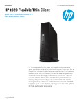
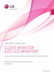
EVGA PCoIP Visual Guide
®
Package Contents
PD01 PCoIP Desktop Portal
®
(7) Rear USB Ports
PColP LED (1)
®
TX/RX
PCoIP
LINK
Portal Power Button (2)
Remote
PC
DVI-2
Front USB Ports (4)
DVI-1
Remote PC Power Button (3)
PD01 Desktop Portal Package Includes:
▪ Portal device with stand
▪ Power adaptor
▪ Power cord
▪ Ethernet cable (2m)
▪ User manual CD
▪ Quick Visual Guide
(8) Ethernet Port
(9) DVI Port 1
(10) DVI Port 2
HC01 PCIe Host Card Package includes:
▪ Host card with full hight and
low profile bracket
▪ DMS-59 to dual DVI cable (45cm)
▪ Power Button cable
▪ Ethernet cable (2m)
▪ User manual CD
▪ Quick Visual Guide
WARNING
1. Always power down and disconnect devices from AC power before handling them.
Failure to do this can result in personal injury or equipment damage. Some circuitry
on the host PC can continue to operate even though the front panel power switch is off.
Headphone Jack (5)
(11) Speaker Jack
Microphone Jack (6)
(12) 12VDC Power Jack
2. The Standalone Mode Power Connector on the host card must be disconnected when
the host card is operating in PCIe powered mode. Failure to do this can result in damage
to the host card.
1 PCoIP Desktop Portal Installation
®
Font
Back
HC01 PCoIP PCI-E Host Card
®
DVI-1 Connector (13)
1
DVI-2 Connector (14)
2
Standalone Mode Power Connector (15)
1. Be sure the monitor and the Portal are turned off and disconnected from AC power.
2. Use a DVI cable to connect the monitor to the Portal’s DVI Port 1 (9).
3. Plug the monitor’s power cable into an AC outlet and power it on.
4. If you are using dual monitors, repeat Steps 1 through 3 but connect the second monitor to the
Portal’s DVI Port 2 (10).
5. Connect a USB keyboard and mouse to the Portal’s rear USB ports (7).
6. Use an Ethernet cable to connect the Ethernet switch or router to the Portal’s Ethernet jack (8).
7. Connect the Portal power supply to the Portal’s power jack (12), then plug the Portal power supply
into a surge-protected AC outlet.
8. Optionally connect the following devices to the Portal:
▪ PC speaker to Speaker jack (11)
▪ Headphones and MIC to Headphone (5) and Microphone jacks (6)
▪ USB peripherals to auxiliary USB ports (4)
9. Power on the Portal by pushing the power button (2). The power button will light steady green and
the monitor will display the On Screen Display (OSD).
Power Button Cable Connector (16)
Standalone Mode Jumper (17)
(18) Disable WOL Jumper
NOTE
(19) Heartbeat LED
(20) Factory Default Reset
If the monitor does not show the On Screen Display (OSD), check all connectors and be sure the
monitor and Portal are powered on. Note the LED indicators:
▪ Off: AC power is off
▪ Solid yellow: AC power is on and Portal power is off
▪ Solid green: Portal power is on
▪ Blinking green: Host PC is in low-power state.
2 PCoIP PCIe Host Card Installation
®
DMS-59 Port (22)
Ethernet Port (21)
(23) PCIe Connector
(24) Wake Configuration Jumper
1. Check the jumpers on the Host card to ensure they are in the correct setting. See Host Card Jumper
Settings for details.
2. Be sure the Host PC is turned off and unplugged from AC power.
3. Open the PC’s case.
EVGA PCoIP Visual Guide
®
4. Install the Host Card into a free PCIe slot and secure the metal bracket.
5. Connect the DMS-59 to dual DVI cable to the Host Card’s DMS-59 connector (22) and connect the
DVI-1 connector (13) to the PC’s graphics card. If you are using dual monitors, connect the graphics
card’s second DVI-out port to the DVI-2 connector (14).
6. Use an Ethernet cable to connect the Ethernet switch or router to the Host Card’s Ethernet jack (21),
then power on the Ethernet switch or router.
7. Close the Host PC’s case and plug the Host PC into a surge-protected AC outlet.
3 Establishing a PCoIP Connection
®
1. Power on the host PC.
2. Wait until the “Connect” button on the Portal On Screen Display (OSD) user screen is active.
Connect
Connect
Connect button is inactive
Connect button is active
®
Host Card Factory Default Reset:
To reset the Host Card to its factory default configuration:
1. Power off the Host PC and disconnect it from AC power.
2. Insert a jumper to the Factory Default Reset header JP1 (20).
3. Power on the Host Card and wait until the heartbeat LED (19) blinks.
4. Power off the Host PC.
5. Remove the Factory Default Reset jumper JP1
Host Card Jumper Settings:
Jumper
3. Use the mouse connected to the Portal to click “Connect” on the OSD screen. The message
“Discovering hosts, please wait …” will appear on the monitor.
4. A list of available Hosts on the network will appear on the OSD.
5. Select the Host Card you wish to connect and click “OK”.
6. The Portal’s PCoIP LED (1) will light green, indicating a successful PCoIP connection.
7. If you are using dual monitors, remember to configure the graphics card for dual-monitor operation.
8. When the Host PC finishes booting, use the Portal as you would a normal desktop PC.
®
The Portal’s Remote PC Power Button (3) is used to remotely control the host PC’s front-panel power switch.
To enable this function, the PCoIP Host Card Power Button Cable must be connected as described in Remote
Power Management.
▪ A short push (< 4 seconds) set the host PC to sleep.
▪ A long push (> 4 seconds) shut down the host PC.
®
JP6 (17)
3
If the “Connect” button on the Portal OSD is inactive or if the Portal can not discover any
Host Cards on the IP network, check the network connection and be sure the Ethernet switch
or router is powered on.
2
1
Settings
STANDALONE
1-2: Standalone powered mode. In this mode, the Host
Card is powered from the standalone mode power
connector J4.
2-3: PCIe powered mode (default)
WAKE CONFIG
1-2: Wake via PCIe slot
2-3: Wake via power button (default)
DISABLE WOL
1-2: Disable wake-on-LAN
2-3: Enable wake-on-LAN (default)
JP12 (24)
3
NOTE
Label
2
1
JP13 (18)
3
2
1
Remote Power Management
During PCoIP sessions, you can use the Portal’s Remote PC Power Button (3) to change the Host PC’s power state.
To enable this function, the PCoIP Host Card Power Button Cable must be connected as described below.
This section assumes you have advanced PC hardware experience.
1. Be sure the Host PC is turned off and unplugged from AC power.
2. Open the PC’s case.
3. Connect the Power Button Cable to the Host Card cable connector (16).
4. Disconnect the PC’s front-panel power button cable from the motherboard. (If the PC uses a single connector for all
front-panel buttons and jacks, disconnecting it will disable all these devices.)
5. Connect the other end of the Power Button Cable to the motherboard’s power switch header. Be sure to connect the
red wire to the power-on pin and the black wire to the ground pin on the PC’s motherboard.
6. If possible, connect the PC’s front-panel power button cable to the 2-pin header on the Power Button Cable. If this is
not possible, the PC’s front-panel power button will be disabled.
7. Close the Host PC’s case and plug the Host PC into a surge-protected AC outlet.
8. Power up the Host PC using the Portal’s Remote PC power button (3). This button can also be used to wake the
Host PC from Sleep states.
®
Additional Notes
Monitor types:
In addition to DVI monitors, the Portal is compatible with analog VGA and digital HDMI monitors.
Simply attach a DVI-to-VGA or DVI-to-HDMI adapter to the Portal’s DVI connector.
Audio:
The Portal uses the Realtek High-Definition Audio Codec. Windows Vista natively contains an HD
Audio driver for this Codec. For other operating systems, including Windows XP, please install the
High-Definition Audio Codec driver from www.realtek.com to use PCoIP System’s full audio capabilities.
IP Address:
The Portal and Host are set to DHCP client mode by default. Normally, the IP address of the Portal and
Host are assigned by the DHCP server on your IP network. If your IP network does not have a DHCP
server, the Portal and Host Card will fall back to a static IP address mode after a timeout period of
approximately 2 minutes. In the fall back static IP address mode, you can access the Portal and
Host web interface to disable DHCP client mode and assign a static IP address.
The Portal’s fall back IP address is 192.168.1.50 and Host’s fall back IP address is 192.168.1.100.
Portal Buttons:
The Portal’s Power Button (2) is a multi-function button.
▪ A short push (< 4 seconds) power on the Portal.
▪ A long push (> 4 seconds) power off the Portal.
▪ When the Portal is connected in a session, a short push will disconnect it from the Host.
®
Need More Help?
Please refer to the documents on the Documentation CD for more information.
This Product Covered By:
The EVGA 2 Year Warranty upon product registration. For more information visit www.evga.com/warranty.
EVGA Support:
888 . 881 . EVGA
www.evga.com