1
Parts Page Reorder No. PD01•40
Effective April, 2001
Supersedes PD98•17
Models:
.7 Hp Dynisher
13400 – 3,400 RPM
13410 – 3,400 Versatility Kit
13411 – 3,400 Versatility Kit
! WARNING
Air Motor and Machine Parts
Always operate, inspect and maintain this tool in accordance with the Safety Code for portable air
tools (ANSI B186.1) and any other applicable safety codes and regulations. Please refer to
Dynabrade’s Warning/Safety Operating Instructions for more complete safety information.
1
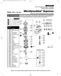
Index Key
No.
Part #
1
2
3
4
5
6
7
8
9
10
11
12
13
14
15
16
17
18
19
20
21
22
23
24
25
26
27
28
29
30
31
53163 Handle Assembly
96278 Screw Assembly (3)
13442 Shroud
40029 Cam Lock
01678 Screw
53167 Handle Support
02552 Bearing (2)
53182 Gear Shaft (2)
53180 Planetary Carrier
53193 Gear (2)
04026 Bearing (4)
53191 Ring Gear
13433 Arbor Adapter
13432 Spindle Cover
50750 Spacer
13434 Flange
13441 Flange
96264 Screw
01007 Bearing
01121 Shim Pack
53183 Front End Plate
01010 Spacer
04017 Rotor
01185 Blades (4/pkg.)
01028 Cylinder
50767 Pin
13440 Rear End Plate
02649 Bearing
04014 Screw
01041 Grease Fitting
13430 Housing Assy.
(includes 13436 Bushing
& 01041 Grease Fitting)
01089 Safety Throttle Lever
13436 Bushing
01017 Pin
13438 Handle Grip
13435 Valve Stem
13439 Ball
07145 Spring
13437 Speed Regulator
01024 O-Ring
13428 Packing
13427 Regulator Plug
01565 Air Control Ring
95438 O-Ring
95711 Retaining Ring
94521 Muffler Base
94528 Muffler
94522 Muffler Cap
95375 O-Ring
94526 Spacer
94523 Inlet Adapter
94519 Muffler Assembly
32
33
34
35
36
37
38
39
40
41
42
43
44
45
46
47
48
49
50
51
52
6
Description
5
2
3
14 A8
16
18
T
15
17
23
21
28 N•m
T
25
27
10
11
7
13 A2
4
7
9
12
17 N•m
8
31
29 A8
28
32
33
20
24 O1
22
A6
26
G1 30
19
36
43
44
34
37
38
45
39
35
40
46
47
41
48
52
42
49
T
8.5 N•m
50
A8 51
A6
T
A
Adhesive: A2 = Loctite #271
A6 = Loctite #380
A8 = Loctite #567
T
Torque: N•m x 8.85 = In. - lbs.
23 N•m
O1
KEY
O
Oil: O1 = Air Lube
G
Grease: G1 = Lubriplate 630AA
Important Operating, Maintenance and Safety Instructions
Carefully read all instructions before operating or servicing any Dynabrade ® Abrasive Power Tool.
Warning: Hand, wrist and arm injury may result from repetitive work motion and overexposure to vibration.
Important: All Dynabrade rotary vane air tools must be used with a Filter-Regulator-Lubricator to maintain all warranties.
Operating Instructions:
Warning: Eye, face, respiratory, sound and body protection must be worn while operating power tools. Failure to do so may result in serious injury or death.
Follow safety procedures posted in workplace.
1. With power source disconnected from tool, securely fasten abrasive/accessory on tool.
2. Install air fitting into inlet bushing of tool. Important: Secure inlet bushing of tool with a wrench before attempting to install the air fitting to avoid
damaging valve body housing.
3. Connect power source to tool. Be careful not to depress throttle lever in the process.
4. Check tool speed with tachometer. If tool is operating at a higher speed than the RPM marked on the tool or operating improperly, the tool should be
serviced to correct the cause before use.
Maintenance Instructions:
1. Check tool speed regularly with a tachometer. If tool is operating at a higher speed than the RPM marked on the tool, the tool should be serviced to
correct the cause before use.
2. Some silencers on air tools may clog with use. Clean and replace as required.
3. All Dynabrade rotary vane air motors should be lubricated. Dynabrade recommends one drop of air lube per minute for each 10 SCFM (example: if
the tool specifications state 40 SCFM, set the drip rate of your filter-lubricator at 4 drops per minute).
Dynabrade Air Lube (P/N 95842: 1pt. 473ml.) is recommended.
4. It is strongly recommended that all Dynabrade rotary vane air tools be used with a Filter-Regulator-Lubricator to minimize the possibility of misuse due
to unclean air, wet air or insufficient lubrication. Dynabrade recommends the following: 11299 Air Line Filter-Regulator-Lubricator — Provides accurate
air pressure regulation, two-stage filtration of water contaminants and micro-mist lubrication of pneumatic components.
Operates up to 100 CFM @ 100 PSIG has 1/2" NPT female ports.
5. Lubricate planetary gears through the gear casing grease fitting with 2-3 plunges for every 50 hours of use, to achieve maximum gear life (order
95542 Grease and 95541 Gun).
6. Use only genuine Dynabrade replacement parts. To reorder replacement parts, specify the Model #, Serial # and RPM of your machine.
7. A Motor Tune-Up Kit (P/N 96234) is available which includes assorted parts to help maintain motor in peek operating condition. Please refer to
Dynabrade's Preventative Maintenance Schedule for a guide to expectant life of component parts.
8. Mineral spirits are recommended when cleaning the tool and parts. Do not clean tool or parts with any solvents or oils containing acids, esters,
keytones, chlorinated hydrocarbons or nitro carbons.
Safety Instructions:
Products offered by Dynabrade should not be converted or otherwise altered
from original design without expressed written consent from Dynabrade, Inc.
•
•
•
•
•
•
Important: User of tool is responsible for following accepted safety codes such as those published by the American National Standards Institute (ANSI).
Operate machine for one minute before application to workpiece to determine if machine is working properly and safely before work begins.
Always disconnect power supply before changing abrasive/accessory or making machine adjustments.
Inspect abrasives/accessories for damage or defects prior to installation on tools.
Please refer to Dynabrade’s Warning/Safety Operating Instructions Tag (Reorder No. 95903) for more complete safety information.
Warning: Hand, wrist and arm injury may result from repetitive work, motion and overexposure to vibration.
Notice
All Dynabrade motors use the highest quality parts and metals available and are machined to exacting tolerances. The failure of quality pneumatic motors can
most often be traced to an unclean air supply or the lack of lubrication. Air pressure easily forces dirt or water contained in the air supply into motor bearings
causing early failure. It often scores the cylinder walls and the rotor blades resulting in limited efficiency and power. Our warranty obligation is contingent
upon proper use of our tools and cannot apply to equipment which has been subjected to misuse such as unclean air, wet air or a lack of lubrication during
the use of this tool.
One Year Warranty
Following the reasonable assumption that any inherent defect which might prevail in a product will become apparent to the user within one year from the date
of purchase, all equipment of our manufacture is warranted against defects in workmanship and materials under normal use and service. We shall repair or
replace at our factory, any equipment or part thereof which shall, within one year after delivery to the original purchaser, indicate upon our examination to
have been defective. Our obligation is contingent upon proper use of Dynabrade tools in accordance with factory recommendations, instructions and safety
practices. It shall not apply to equipment which has been subject to misuse, negligence, accident or tampering in any way so as to affect its normal
performance. Normally wearable parts such as bearings, contact wheels, rotor blades, etc., are not covered under this warranty.
Model
Number
Motor
HP (W)
Motor
RPM
Air Inlet
Thread
Sound
Level
Air Flow Rate
CFM/SCFM (LPM)
Machine Dia.
Inch (mm)
Wheel Arbor Dia.
Inch (mm)
Weight
Pound (kg)
Length
Inch (mm)
Height
Inch (mm)
13400
.70 (522)
3,400
1/4" NPT
88 dB(A)
6/44 (1,246)
1-13/16 (46mm)
3/4 (19mm)
4.6 (2)
10-3/4 (274)
9 (229)
Additional Specifications: Hose I.D. Size 3/8" (10mm) • Max. SFPM 4450 (SMPM 1350) • 90 PSIG (6.2 Bars)
(PD01•40)
2
Disassembly/Assembly Instructions - Dynisher
Important: Manufacturer’s warranty is void if tool is disassembled before warranty expires.
Please refer to parts breakdown for part identification.
Motor Disassembly:
1. Disconnect tool from power source. Remove pneumatic wheel or accessory from spindle.
2. Loosen 01678 Lock Screw and remove handle assembly. Remove flange and spacer from motor shaft.
3. Secure motor housing using padded vise with motor spindle facing upwards.
4. Using an adjustable pin wrench, remove 13432 Spindle Cover.
5. Remove 04014 Set Screw from housing.
6. Pull 13433 Arbor Adapter and planetary carrier assembly from housing.
7. Press planetary carrier assembly from rear 02552 Bearing. Remove ring gear and gears from 53180 Planetary Carrier.
8. Secure planetary carrier in vise and remove 13433 Arbor Adapter. Press carrier from front 02552 Bearing.
9. Grab onto 04017 Rotor/Pinion and pull motor assembly from motor housing.
10. Press 04017 Rotor/Pinion from 13440 Rear Bearing Plate. Press 02649 Rear Bearing from rear bearing plate.
11. Remove 01028 Cylinder and 01185 Rotor Blades from rotor.
12. Press rotor pinion assembly through 01007 Front Bearing and 53183 Front Bearing Plate.
Motor Disassembly Complete.
Housing Disassembly:
1. Position housing in padded vise with air inlet facing up.
2. Remove air fitting by securing 94523 Inlet Adapter with a wrench and twist air fitting from inlet adapter.
Important: 94523 Inlet Adapter must be secured before attempting to remove air fitting to avoid damaging valve body housing.
3. Remove 94523 Inlet Adapter.
4. Remove 95711 Retaining Ring from inlet adapter and separate 94521 Muffler Base from 94522 Muffler Cap. Remove 94528 Felt Muffler.
5. Remove 01565 Air Control Ring from housing.
6. Using a 2.5mm drift pin, tap 01017 Pin from housing and remove throttle lever assembly.
7. Remove 13427 Plug. Pull 13437 Speed Regulator from housing and remove 01024 O-Rings, 07145 Spring, 13439 Ball, and 13435 Valve Stem.
Disassembly Complete.
Motor Assembly:
Important: Be sure parts are clean and in good repair before assembly. Follow all grease, oil, and torque specifications.
1. Place 04017 Rotor in padded vise with threaded spindle facing upwards.
2. Slip 01010 Spacer onto 04017 Rotor.
3. Place a .002" shim into 53183 Front Bearing Plate as an initial spacing and slip 01007 Bearing into plate. Note: 01121 Shim Pack contains .001"
and .002" shims.
4. Press bearing/bearing plate assembly onto rotor.
5. Check clearance between rotor and bearing plate by using a .001" feeler gauge. Clearance should be at .001" to .0015". Adjust clearance by repeating
steps 2-4 with different shim if necessary.
6. Once proper rotor gap clearance is achieved, install well lubricated 01185 Blades (4) into rotor slots. Dynabrade recommends using their
95842 Air Lube.
7. Install cylinder over rotor/pinion. Be sure air inlet holes of cylinder face away from 53183 Front Bearing Plate.
8. Press 02649 Rear Bearing into 13440 Rear Bearing Plate. Press bearing/bearing plate assembly onto rotor. Be sure that pin and air inlet holes line up
with pin slot and air inlet holes in cylinder. Important: Fit must be snug between bearing plates and cylinder. If too tight, rotor will not turn freely. Rotor
must then be lightly tapped at press fit end so it will turn freely while still maintaining a snug fit. A loose fit will not achieve the proper preload
of motor bearings.
10. Secure motor housing in padded vise so motor cavity faces upwards. Install motor assembly into housing. Be sure motor inlet is facing the handle and
it drops all the way into housing.
11. Press front 02552 Bearing onto front end of 53180 Planetary Carrier.
12. Apply #271 Loctite ® to 13433 Arbor Adapter and install onto 53180 Planetary Carrier (torque 17.0 N•m/150 in. - lbs.).
13. Install 53193 Gears, 04026 Bearings and 53182 Gear Shafts onto planetary carrier.
14. Slip 53191 Ring Gear over gears and press rear 02552 Bearing onto planetary carrier.
15. Apply two drops of #271 Loctite ® to threads of 13432 Spindle Cover.
16. Install 13432 Spindle Cover onto housing to secure motor (torque 28 N•m/250 in. - lbs.).
Motor Assembly Complete.
Housing Assembly:
1.
2.
3.
4.
5.
6.
Install 13438 Handle Grip.
Insert 13435 Valve Stem through housing and into hole in 13436 Bushing.
Insert 13439 Ball, 07145 Spring, 13437 Speed Regulator with 01024 O-Ring in place.
Install 13428 Packing onto 13427 Regulator Plug. Secure plug in place torque 8.5 N•m/75 in. - lbs.
Insert 94528 Muffler into 94522 Muffler Cap. Install 94521 Muffler Base onto muffler cap.
Install 94538 O-Ring into groove on muffler base. Place 95375 O-Ring and 94526 Spacer into recessed area of muffler cap.
(continued on next page)
3
Disassembly/Assembly Instructions (continued)
7. Slip 94523 Inlet Adapter through muffler assembly and install 95711 Retainer Ring into groove on inlet adapter.
8. Install 01565 Air Control Ring into housing.
9. Apply Loctite ® #567 to threads of 94523 Inlet Adapter and install entire muffler assembly onto housing inlet (torque 23.0 N•m/200 in. - lbs.).
10. Replace air fitting. Secure inlet adapter with a wrench before tightening air fitting.
11. Install throttle lever and 01017 Pin.
Tool Assembly is complete. Please allow 30 minutes for adhesives to cure before operating tool.
Important: Motor should now be tested for proper operation at 90 PSIG. If motor does not operate properly or operates at a higher RPM than marked on the
tool, the tool should be serviced to correct the cause before use. Before operating, place 2-3 drops of Dynabrade Air Lube (P/N 95842) directly into air inlet
with throttle lever depressed. Operate tool for 30 seconds to determine if tool is operating properly and to allow lubricating oils to properly penetrate motor.
Loctite ® is a registered trademark of Loctite Corp.
Optional Accessories
Dynaswivel ®
Swivels 360° at two locations which allows an
air hose to drop straight to the floor, no matter
how the tool is held.
Note: For proper connection to a 1/4" NPT
thread a reducing bushing is required.
• 95461 3/8" NPT.
96234 Motor Tune-Up Kit
• Includes assorted parts to help
maintain and repair motor.
94473 Dynacushion ® Pneumatic Wheel
• Easily regulate hardness by air pressure.
• 5" Diameter x 3-1/2" Wide.
• Inflates to 20 PSIG maximum.
• 3-1/2" wide x 15-1/2" long belt size.
94465 Wheel Inflation Tool
• Controlled inflation/deflation of
pneumatic wheel.
• Has 1/4" female thread; fits 1/4" air hose.
• 95633 Nozzle Replacement available.
95542 Grease 10 oz.
• Multi-purpose grease for all types of bearings,
cams, gears.
• High film strength; excellent resistance to
water, steam, etc.
• Workable range 0˚ F to 300˚ F.
95541 Push-type Grease Gun
• One-hand operation
Dynabrade Air Lube
• Formulated for pneumatic equipment.
• Absorbs up to 10% of its weight in water.
• Prevents rust and formation of sludge.
• Keeps pneumatic tools operating longer
with greater power and less down time.
95842: 1pt. (473 ml)
95843: 1gal. (3.8L)
53159 Shroud Assembly
• Extended length to enclose 4 inch wide
abrasive accessories.
®
Visit Our Web Site: www.dynabrade.com
Email: [email protected]
DYNABRADE
DYNABRADE, INC., 8989 Sheridan Drive • Clarence, NY 14031-1490 • Phone: (716) 631-0100 • Fax: 716-631-2073 • International Fax: 716-631-2524
DYNABRADE EUROPE S.àr.l.,
Zone Artisanale • L-5485 Wormeldange—Haut, Luxembourg • Telephone: 352 76 84 94 1 • Fax: 352 76 84 95 1
© DYNABRADE, INC., 2004
PRINTED IN USA
PD01.40_Rev.1_02/04