1
ILS-CON
ILS™ Control Center
USER MANUAL
th
Chauvet, 3000 N 29 Ct, Hollywood, FL 33020 U.S.A
(800) 762-1084 – (954) 929-1115
FAX (954) 929-5560
www.chauvetlighting.com
TABLE OF CONTENT
BEFORE YOU BEGIN ............................................................................................................................................................... 3
WHAT IS INCLUDED ...................................................................................................................................................................... 3
UNPACKING INSTRUCTIONS ........................................................................................................................................................... 3
SAFETY INSTRUCTIONS ................................................................................................................................................................ 3
INTRODUCTION ........................................................................................................................................................................ 4
FEATURES ................................................................................................................................................................................. 4
PRODUCT OVERVIEW................................................................................................................................................................... 4
Control Center (left side) ................................................................................................................................................... 4
Control Center (right side)................................................................................................................................................. 5
Rear Panel......................................................................................................................................................................... 5
Rear Panel......................................................................................................................................................................... 6
SETUP ........................................................................................................................................................................................ 7
CONNECTION DIAGRAM ................................................................................................................................................................ 7
COMMON TERMS ........................................................................................................................................................................ 8
OPERATING INSTRUCTIONS.................................................................................................................................................. 9
SETUP....................................................................................................................................................................................... 9
Setting up the System ............................................................................................................................................................................ 9
ILS™ Fixture Addressing (Patching) ....................................................................................................................................................... 9
Non-ILS™ Fixture Addressing (Patching).............................................................................................................................................. 10
PROGRAMMING ......................................................................................................................................................................... 11
Entering Program Mode ....................................................................................................................................................................... 11
Programming Fixtures .......................................................................................................................................................................... 11
Create a Scene.................................................................................................................................................................................... 11
Apply Movement Effect to a Scene ....................................................................................................................................................... 12
Previewing Memory (Scene or Chase).................................................................................................................................................. 12
Create a Chase.................................................................................................................................................................................... 13
Overwrite a Program ............................................................................................................................................................................ 13
Delete a Program ................................................................................................................................................................................. 13
Delete a Step....................................................................................................................................................................................... 14
Clear All Memory ................................................................................................................................................................................. 14
PLAYBACK ............................................................................................................................................................................... 14
Running the Show (Light Show Mode) .................................................................................................................................................. 14
Using the Integrated CA-8 controller ..................................................................................................................................................... 15
Using the Integrated Strobe Controller .................................................................................................................................................. 15
Using the Fog Machine Trigger............................................................................................................................................................. 15
Blackout............................................................................................................................................................................................... 15
Fixture Override ................................................................................................................................................................................... 15
PROGRAMMING SHORTCUTS ....................................................................................................................................................... 16
CONTROLLER PRESET TRAIT SELECTIONS (VISUAL QUICK-CHART)................................................................................................... 17
MIDI OPERATION ....................................................................................................................................................................... 17
APPENDIX................................................................................................................................................................................ 19
CA-8 COMPATIBLE FIXTURES ..................................................................................................................................................... 19
DMX PRIMER ........................................................................................................................................................................... 19
Fixture Linking ..................................................................................................................................................................................... 19
MAINTENANCE .......................................................................................................................................................................... 21
RETURNS PROCEDURE .............................................................................................................................................................. 21
CLAIMS ................................................................................................................................................................................... 21
GENERAL TROUBLESHOOTING ..................................................................................................................................................... 22
TECHNICAL SPECIFICATIONS ....................................................................................................................................................... 23
ILS-CON User Manual
2
3/28/2005 3:03:00 PM
BEFORE YOU BEGIN
What is included
1 x ILS-CON “ILS™ Control Center”
DC 9V power adapter
Manual with warranty card
Unpacking Instructions
Immediately upon receiving a fixture, carefully unpack the carton, check the contents to ensure that
all parts are present, and have been received in good condition. Notify the shipper immediately and
retain packing material for inspection if any parts appear damaged from shipping or the carton itself
shows signs of mishandling. Save the carton and all packing materials. In the event that a fixture
must be returned to the factory, it is important that the fixture be returned in the original factory box
and packing.
Safety Instructions
Please read these instructions carefully, which includes important
information about the installation, usage and maintenance?
Caution!
Please keep this User Guide for future consultation. If you sell the unit to another user, be sure that
they also receive this instruction booklet.
Always make sure that you are connecting to the proper voltage and that the line voltage you are
connecting to is not higher than that stated on decal or rear panel of the fixture.
This product is intended for indoor use only!
To prevent risk of fire or shock, do not expose fixture to rain or moisture. Make sure there are no
flammable materials close to the unit while operating.
The unit must be installed in a location with adequate ventilation, at least 50cm from adjacent
surfaces. Be sure that no ventilation slots are blocked.
Always disconnect from power source before servicing or replacing lamp or fuse and be sure to
replace with same lamp source.
In the event of serious operating problem, stop using the unit immediately. Never try to repair the unit
by yourself. Repairs carried out by unskilled people can lead to damage or malfunction. Please
contact the nearest authorized technical assistance center. Always use the same type spare parts.
Don’t connect the device to a dimmer pack.
Make sure power cord is never crimped or damaged.
Never disconnect power cord by pulling or tugging on the cord.
Do not operate this device under 113° F ambient temperature conditions.
There are no user serviceable parts inside the unit. Do not open the housing or attempt
any repairs yourself. In the unlikely event your unit may require service, please contact
CHAUVET.
ILS-CON User Manual
3
3/28/2005 3:03:00 PM
INTRODUCTION
Features
DMX address ILS™ intelligent lighting fixtures from the ILS™ Control Center
Independently control up to 24 ILS™ fixtures or 24 8-channel DMX devices
12 preset movement effects for quick programming
24 playbacks as scene or chase
485 total scene memory
2 integrated CA-8 controllers
integrated variable strobe trigger
integrated fog trigger
blackout button
chase speed slider
fade speed slider
built in microphone for sound activation
midi input triggering
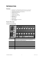
Product Overview
Control Center (left side)
Down
Up
Full On
Mode
BUTTON OR FADER
FUNCTION
Stand Alone 1 & 2
Equivalent of 2 CA-8 remote controllers, for master/slave triggering of
compatible fixtures. (see appendix section “CA-8 Compatible Fixtures”
Requires optional CA-CBL Linking cable
Scanners
Enables selection of fixtures for programming
Movement (trait)
Enables the selection of 12 preset movement patterns
Shutter (trait)
Enables shutter settings
Gobo (trait)
Enables gobo selection
Color (trait)
Enables color selection
Rotation (trait)
Enables gobo rotation selection
Dimmer (trait)
Enables dimmer selection
Focus (trait)
Enables motorized focus selection
Buttons 1~8 / 13~20
Universal keys for the selection of fixtures, preset fixture traits and memory
ILS-CON User Manual
4
3/28/2005 3:03:00 PM
Introduction
Control Center (right side)
BUTTON OR FADER
FUNCTION
Page
Toggles between page 1 and page 2 comprised of 12 memory locations
in each
Memory
Enables memory location selection
Cancel
Used either to delete a program or to cancel out of a function or
unwanted process
Save
Used to save a program
Buttons 9~12 / 21~24
Universal keys for the selection of fixtures, traits and memory
Auto/Sound/Manual
In Light Show mode toggles between Auto, Sound and Manual modes
Light Show
Enables the show mode for playback
Blackout
Provides a blackout function and activates Stand/Alone mode
Joystick
For pan & tilt movement of intelligent lights
Press down to activate FINE pan/tilt movement
FINE
Provides a slower and more accurate response to Pan & Tilt movement
using the joystick.
Override
Allows an overriding manual control of fixtures while in Light Show
mode
Fog
Triggers fog machine
Strobe
Momentary strobe trigger
Speed (fader)
- Used to adjust the hold or wait time of a scene while in Light Show
mode
- Varies the tilt output in Scanner function
- Varies the tilt range in Movement function
XFade (fader)
- Used to adjust the time between steps within a chase while in Light
Show mode
- Varies the pan output in Scanner function
- Varies the pan range in Movement function
ILS-CON User Manual
5
3/28/2005 3:03:00 PM
Introduction
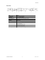
Rear Panel
ITEM
FUNCTION
1. Power Switch
Turns the device ON and OFF.
2. DC Input
DC 9~12V, 300mA minimum
3. DC Fog Machine
DC Fog Machine Type remote trigger (5-pin Din)
4. Strobe
Outputs +12V DC for the control of Strobes
5. Audio In
Audio line input
6. Midi In
Midi input
7. DMX In
DMX data input locking 3-pin XLR male socket
8. DMX Out
There are two DMX output connectors on the ILS-CON, also referred to
as Loop1 and Loop2
Locking 3-pin XLR female socket
9. Stand Alone
5-pin XLR to ¼” phone jack for CA-8 Easy Controller compatible fixtures
for Master/Slave Mode operation
10. AC Fog Machine
AC Fog Machine Type remote trigger
ILS-CON User Manual
6
3/28/2005 3:03:00 PM
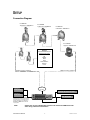
SETUP
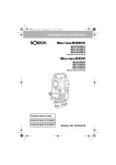
Connection Diagram
ILS-606DSR
Trackscan™ 250DSR-ILS
ILS-606DBR
Trackscan™ 250DBR-ILS
ILS-625DCR
Colortrack™ 250DCR-ILS
ILS-515DMR
Legend™ 150DMR-ILS
Non-ILS
8-channel DMX devices
Preferred Trait Order
Pan
Tilt
Shutter
Gobo
Color
Gobo Rotation
Dimmer
Focus
DMX-512 / ILS™ Output #2
CA-8 Easy
Controller #1
DMX-512 / ILS™ Output #1
1 DMX-512
Universe
Variable Strobe Controller
CA-8 Easy
Controller #2
FOG MACHINE
The CA-8 Easy Controller provides
additional wired remote functionality to a
designated range of CHAUVET lighting
fixtures. Depending on the fixture the
Function and Mode buttons will have
varying affect.
Note!
Please refer to your individual ILS product’s user manual for DMX-512 and all
other wiring connection instructions!
ILS-CON User Manual
7
3/28/2005 3:03:00 PM
Setup
Common Terms
The following are common terms used in using the ILS-CON Control Center.
Blackout is a state by where all lighting fixtures light output are set to 0 or off, usually on a temporary
basis.
DMX-512 is an industry standard digital communication protocol used in entertainment lighting
equipment. For more information read Sections “DMX Primer” and “DMX Control Mode” in the
Appendix.
Fixture refers to your lighting instrument or other device such as a fogger or dimmer of which you can
control.
Programs are a series of scenes stacked one after another. It can be programmed as either a single
scene or multiple scenes in sequence. Up to 485 scenes can be stored in a single program. A
program can also be considered a chase.
Scenes are static lighting states.
Sliders also known as faders. There are 2 physical sliders on the ILS-CON Control Center.
Chases can also be called programs. A chase consists of a bunch of scenes stacked one after
another. In the ILS-CON every step or scene within the chase can be composed with a movement
effect.
Movement Effects are pre-constructed Pan/Tilt movements that can be applied to a scene. There
are 12 movement effects in the ILS-CON.
Scanner refers to a lighting instrument with a pan and tilt mirror; however, in the ILS-CON controller it
can be used to control any DMX-512 compatible device as a generic fixture.
MIDI is a standard for representing musical information in a digital format. A MIDI input would provide
external triggering of scenes using midi device such as a midi keyboard.
Stand Alone refers to a fixture’s ability to function independently of an external controller and usually
in sync to music, due to a built in microphone.
XFADE slider is used to adjust the time between scenes within a chase.
Speed slider affects the amount of time a scene will hold its state. It is also considered a wait time.
Shutter is a mechanical device in the lighting fixture that allows you to block the lights path. It is often
used to lessen the intensity of the light output and to strobe.
Patching on the ILS™ Controller is refers to the process of assigning fixtures to any of the Buttons
1~24.
ILS™ stands for Integrated Lighting System. A component of the ILS™ System is an enhanced
version of the DMX-512 protocol that maintains backwards compatibility. The ILS™ protocol enables
the ILS™ Controller to remotely DMX-512 address fixtures that are ILS™ enabled. Further more, the
ILS™ System allows the control of various types of intelligent fixtures in a unison manner providing
faster and efficient use of the controller.
Playbacks can be either scenes or chases that are directly called to execution by user action. A
playback can also be considered program memory that can be recalled during a show or running
mode.
ILS-CON User Manual
8
3/28/2005 3:03:00 PM
OPERATING INSTRUCTIONS
Setup
SET T I NG UP T HE SYST EM
1)
Place the ILS-CON on a leveled surface. Note! The ILS-CON can also be rack mounted,
occupying 3U spaces.
2)
Plug the AC to DC power supply to the system back panel and to the mains outlet.
3)
Plug in your DMX cable(s) to your intelligent lighting as described in the fixtures respective
manual. For a quick Primer on DMX see the “DMX Primer” section in the Appendix of this
manual. Refer to the “Connection Diagram” section of this manual to assist you.
4)
Plug in any CA-8 compatible fixtures to the integrated CA-8 controller interface. See “CA-8
Compatible Fixtures” in the appendix section for a list of compatible Chauvet products.
5)
Plug in a compatible Chauvet Fogger to the AC Fog Machine Remote Controller connector.
6)
Plug in any Chauvet MONO strobes in a daisy like fashion using a ¼” mono phone cable.
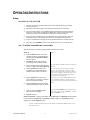
I L S™ F I XT URE ADDRESSI NG (PAT CHI NG )
With the ILS-CON you are able to remotely DMX-512 address ILS™ fixtures.
Notes
Action
1)
Press the Blackout button for at least 3
complete seconds or until the LED blinks.
This will enable the Stand/Alone Mode for
the ILS™ fixtures.
2)
Hold Scanner button down and bump
(momentarily press) the blackout button.
3)
Wait for the lights and their LED displays to
come to a complete stop. (Very important!)
The only LED that will blink will be the first fixture in
the Loop.
4)
Push the joystick down until it clicks.
First fixture in the chain should light up,
otherwise read the notes in this section.
This will place focus on the first fixture in DMX
output # 1, also called Loop1. There are 2 DMX
outputs in the controller, Loop1 and Loop2. The first
light in Loop1 will light up if it does not, then you are
not connected to Loop1 but Loop2. Jump loops by
moving the joystick left and right.
5)
Move the joystick left or right to jump
Loops. The first ILS™ fixture connected to
each Loop will light immediately.
6)
Up/Down joystick movement will traverse
forwards and backwards along the fixtures.
Tip! If you get lost, you probably pushed the joystick
to the side and jumped Loops. Click the joystick to
jump to fixture 1 on Loop1 and repeat step mentioned
above.
7)
Press any one of the Buttons 1~24 to
patch the fixture accordingly.
8)
Optional – Step # 4
Pressing the SCANNERS button will toggle between
pages. Page 1 allows access to (Buttons 1 ~ 12) and
Page 2 to (Buttons 13 ~ 24).
Shortcut: [Blackout] – Hold 3sec (LED blinks) Hold [Scanner] & Tap [Blackout] Wait for lights
to stop! Push to click [Joystick] [Joystick] Left/Right change Loop [Joystick] Up/Down
change fixture Press [Button] to patch.
Tip! You can address multiple lights to the same address. Instead of independent control, you will
have unison control.
ILS-CON User Manual
9
3/28/2005 3:03:00 PM
Operating Instructions
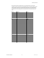
Physical DMX Channel Addresses (ILS™) fixtures
Fixture Number
1
2
3
4
5
6
7
8
9
10
11
12
DMX channel for
Moving Head, Scanner,
Barrel
1
9
17
25
33
41
49
57
65
73
81
89
Color changer
3
11
19
27
35
43
51
59
67
75
83
91
Fixture Number
13
14
15
16
17
18
19
20
21
22
23
24
DMX channel for
Moving Head, Scanner,
Barrel
97
105
113
121
129
137
145
155
161
169
177
185
Color changer
99
107
115
123
131
139
147
157
163
171
179
187
NO N-I L S™ FI XT URE ADDRESSI NG (P AT CHING )
Although the ILS-CON was especially designed for the control of ILS™ products, it can control other
DMX-512 fixtures or devices with a little bit of ingenuity. The ILS-CON control buttons are laid out and
based on the DMX attributes of ILS™ fixtures. The controller expects the devices to want 8 channels
of DMX control, and that those channels be in the following order; Pan, Tilt, Shutter, Gobo, Color,
Gobo Rotation, Dimmer and Focus. If some of your intelligent lighting products do not exceed 8
channels, you will be able to control those devices, irrespective of the labeling on the controller.
Every control button that pertains to a fixture trait can also be controlled through the slider. By default
selecting the Scanner button will control channel 1 and 2 of the DMX chain enabling joystick control.
But it also uniquely activates both available sliders on the controller. It is important to know that
selecting the Movement button releases control of the sliders and enables the selection of 12 preset
movement effects. The joystick will still be available but only for changing the position of the effect. To
regain control of the pan & tilt movement or channel 1 and channel 2 of DMX then press the
Movement button again to release effects. If you were controlling a fixture with no pan or tilt, channel
1 and 2 could still be controlled either by the joystick or the two sliders. On the other hand if the pan
and tilt were located on other channels, then you could use the XFADE slider to affect change. It is
recommended that you program non-ILS™ fixtures individually. Non-ILS™ fixtures would require
physical DMX addressing in 8 channel increments starting with channel 1. Please refer to your
fixture’s manual for DMX channel addressing method.
Physical DMX Channel Addresses (non-ILS™) fixtures
Fixture Number
1
2
3
4
5
6
7
8
9
10
11
12
DMX channel
1
9
17
25
33
41
49
57
65
73
81
89
Fixture Number
13
14
15
16
17
18
19
20
21
22
23
24
DMX channel
97
105
113
121
129
137
145
155
161
169
177
185
ILS-CON User Manual
10
3/28/2005 3:03:00 PM
Operating Instructions
Programming
ENT ERI NG PRO G RAM MO DE
By default when the ILS-CON is turned on, it will enter the program editor (mode). The LED on the
Blackout/Stand-Alone button will be set to the OFF state.
1)
While in any other mode, simply continue to press the Blackout button until the LED turns OFF.
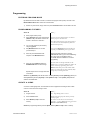
PRO G RAMMI NG F I XT URES
Notes
Action
1)
Enter program editor (mode)
2)
Select Scanners button then select fixtures
(Buttons 1~24). The default control is Pan
and Tilt or Channel 1 & Channel 2.
Tip! You can choose multiple fixtures. To deselect
fixtures just press the button twice.
Press the Scanners button to toggle between fixtures
1~12 and 13~24 as indicated by the top LED and
bottom LED respectively.
3)
You can now control the pan and tilt by
using the joystick.
4)
Skip Movement button for now and
proceed to step 5.
If you pressed Movement and the joystick does not
respond, press Movement again to regain control.
5)
Select any of the trait buttons with
exception of the Movement button.
Tip! Program faster and easier by selecting
individual traits such as gobos, colors and dimming.
Go to page 18 for a Visual Quick Chart of
“Controller Preset Trait Selections” to assist in
programming.
6)
Select any of the Buttons 1~24 or the
XFADE/VALUE slider to affect change.
Open the shutter on the light and make sure the
dimmer level is set to full. In addition, the sliders can
also be used when programming fixture traits.
Repeat steps 5 and 6 to change other traits
of the fixture.
Buttons 1~24 contain preset values and the slider
allows you to adjust the trait values manually. Refer
to Page 18 for a Visual Quick Chart.
Shortcut: Tap [Blackout] until LED turns OFF Select [Scanner] Select [Button(s)] (fixtures)
Select [trait button] Move [Joystick] or select [Buttons 1~24] or move [sliders] Repeat trait
selection and modification
CRE AT E A SCENE
A scene is a static lighting state. The ILS-CON can store 24 playbacks consisting of either a static
scene or a series of scenes forming a chase.
Action
Notes
1)
Program fixtures.
See “Programming Fixtures” above.
2)
Press the Save button.
Buttons LED will light up that contain previously
stored programs.
3)
Select Buttons (1~24) to store into
memory.
The buttons section will now turn into memory
locations 1 ~ 24. Press Page button to toggle between
Buttons(1~12) & Buttons(13~24)
Shortcut: {Programming Fixtures} Press [Save] Select [Button 1~24] to store to memory
ILS-CON User Manual
11
3/28/2005 3:03:00 PM
Operating Instructions
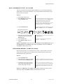
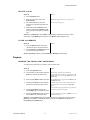
APPL Y MO VEMENT EFF ECT T O A SCENE
There are 12 preset Pan/Tilt movement programs available for you to choose while programming
intelligent lights. These are also called effects. You can apply a different movement effect to every
step in a chase if you so desire.
Notes
Action
1)
Enter program editor (mode)
2)
Select Scanners button and select
fixture(s) (Buttons 1~24).
You can choose multiple fixtures. To deselect fixtures
just press the button twice. Tap the Scanners button
to toggle between fixtures 1~12 and 13~24 as
indicated by the top LED and bottom LED
respectively. This is called changing pages. You will
notice that not all trait buttons have 2 pages, so
therefore only buttons 1 ~ 12 are available.
3)
Press the Movement trait.
Tip! Quickly open the shutter on the light by pressing
Shutter and Button #2. Then return to Movement.
12 Programmed movement effects
1
2
3
4
5
6
7
8
9
10
11
12
4)
Select any of the 12 movement effects
available by pressing any one of the
Buttons (1~12).
To disable effects or to return control to the joystick
tap Movement again.
5)
Press the Save button.
6)
Select Buttons (1~24) to store into
memory.
The buttons section will now turn into memory
locations 1 ~ 24 for playback.
Shortcut: Tap [Blackout] until LED turns OFF Select [Scanner] Select [Button(s)] (fixtures)
Select [Movement] Select [Buttons 1~12] Select other [traits] & modify Press [Save]
Select [Button 1~24] to store to memory
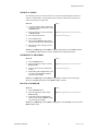
PREVI EWI NG MEMO RY (SCENE O R CHASE)
While in the program editor, you can preview a scene or chase. A chase consists of one or more
scenes. Every scene within a chase is considered a step. We will use the term scene and step
interchangeably through out this manual.
Notes
Action
1)
Press the Memory button.
2)
Select the scene or chase you previously
stored represented by Buttons (1~24).
Remember! The Page button toggles between Page 1
and Page 2 giving you access to memory locations 13
~ 24.
3)
If previewing a chase, simply press the
same memory button again to preview
another existing step in the chase.
There is no way of traversing backwards so if you
pass a step you wanted to edit you will need to either
continue forward until it loops back again or select
another memory button and then return to the one
desire.
Shortcut: Press [Memory] Select [Button 1~24] (program) Select same button to preview
another step Select other [Button 1~24] to preview another scene or chase
ILS-CON User Manual
12
3/28/2005 3:03:00 PM
Operating Instructions
CRE AT E A CH ASE
As mentioned previously, a chase consists of one or more scenes stepped together. Scenes in a
chase are considered steps. The ILS-CON can store a maximum of 485 scenes and all of those
scenes can be stored in a single chase.
Notes
Action
1)
A chase is created by adding another step
to the same program memory button. Press
the Memory button.
2)
Select the program you wish to add a step
to. Buttons (1~24).
3)
See “Programming Fixtures”
4)
Press the Save button.
5)
Select the same Button (1~24) originally
selected to add this newly created scene to.
6)
Repeat steps number 3 through 5 to add
more scenes.
Page button toggles between (1~12) and (13~24).
See instructions on page 12.
Shortcut: Press [Memory] Select [Button 1~24] {Program fixtures} Press [Save] Select
the same [Button 1~24] to add step to memory Repeat from {Programming Fixtures}
O VERWRI T E A PRO G RAM
Notes
Action
1)
Press the Memory button.
2)
Select the program you wish to overwrite.
Buttons (1~24).
3)
4)
Create a new scene. See “Programming
Fixtures”
Page button toggles between (1~12) and (13~24).
See instructions on page 12.
While holding down the Save button, press
the program button Buttons (1~24) you
previously selected again.
Shortcut: Press [Memory] Select [Button 1~24] (program) Create new scene {Program
fixtures} Hold [Save] and press the same [Button 1~24] to overwrite
DEL ET E A PRO G RAM
Notes
Action
1)
Press the Memory button.
2)
Select the program you wish to delete.
Buttons (1~24).
3)
While holding down the Cancel button,
press the program button Buttons (1~24)
you previously selected again.
Page button toggles between (1~12) and (13~24).
Shortcut: Press [Memory] Select [Button 1~24] (program) Hold [Cancel] and press the same
[Button 1~24] to delete
ILS-CON User Manual
13
3/28/2005 3:03:00 PM
Operating Instructions
DEL ET E A ST EP
Notes
Action
1)
Press the Memory button.
2)
Select the program you wish to edit.
Buttons (1~24).
3)
4)
See “Previewing Memory” above for
instructions on selecting a step within this
program.
Page button toggles between (1~12) and (13~24).
See instructions on page 13.
While holding down the Memory button,
press the program button Buttons (1~24)
you previously selected again to delete the
step.
Shortcut: Press [Memory] Select [Button 1~24] (program) Select same button to preview
another step Hold [Memory] & and press the same [Button 1~24] to delete the step
CL EAR AL L MEMO RY
Notes
Action
1)
Press the Blackout button for at least 3
complete seconds or until the LED blinks.
2)
Press the Memory and Blackout buttons at
the same time to erase all memory.
Shortcut: [Blackout] Hold 3secs Press [Memory] & [Blackout] simultaneously
Playback
RUNNI NG T HE SHO W (LI G HT SHO W MO DE)
You will need to program scenes or chases in order to use this mode.
Notes
Action
1)
Press the Light Show button
2)
The first mode you will encounter will be the
Auto mode, indicated by LED number 1.
In Auto mode, programs selected will loop
automatically. You can change the speed of the chase
and the Fade time by moving the Speed slider and the
XFade slider.
3)
Select program [Button 1~24) for playback.
Tap the Page button to toggle between Buttons 1~24
and Buttons 13~24.
4)
Pressing the A-S-M button will activate the
Sound mode, indicated by LED number 2.
5)
Pressing the A-S-M button again will
activate MIDI triggering, indicated by LED 3.
6)
Pressing the A-S-M button again will revert
back to Auto mode, indicated by LED 1.
A-S-M is short for Auto – Sound – Midi, and it refers
to the button directly to the left of the Light Show
button.
In the Sound mode, programs will be triggered by the
sound using its built-in microphone.
Programs would be triggered by a MIDI device, such
as a MIDI keyboard.
Shortcut: Press [Light Show] default (Auto Mode) Optional: Choose another mode by pressing
[A-S-M] (2 Sound Mode, 3 MIDI Mode) Select programs using [Button 1~24] Optional:
nd
rd
Modify [Speed] and [XFADE] sliders
ILS-CON User Manual
14
3/28/2005 3:03:00 PM
Operating Instructions
USI NG T HE I NT EG RAT ED CA-8 CO NT RO L LER
The CA-8 Easy Controller provides additional wired remote functionality to a
designated range of CHAUVET lighting fixtures. Depending on the fixture the
Function and Mode buttons will have varying affect. The ILS™ Control Center has
2 individual integrated CA-8 controllers. You will need (2) CA-CBL linking cables to
begin the chain. Cables are sold separately.
You will need to consult with your individual fixture’s manual for a detailed
description of the controlled parameters. Below is a general description of what the
individual buttons will do.
BUTTON
ACTION
STAND BY
In general, this function will provide a blackout mode to all units connected.
FUNCTION
The function button is a multi-purpose button providing for the selection of minor
program changes, such as strobing, step advancement, fast/slow selection and more
features that depend on the particular CA-8 compatible lighting fixture you are
controlling. The user will need to review the section about the CA-8 Easy Controller in
the Users Manual of the lighting fixture he/she is controlling to determine the specific
outcome.
MODE
This button also serves a multi-purpose function. Depending on the lighting fixture, the
mode button could make available the selection of programs, audio enable or
slow/fast speeds.
USI NG T HE I NT EG RAT ED ST RO BE CO NT RO L L ER
Press the Strobe button to activate the strobes. You can vary the strobe rate by holding down the
Strobe button and selecting Buttons 1~12. You will notice that the Strobe LED will blink at different
rates as you select different Buttons 1~12.
USI NG T HE FO G MACHI NE T RI G G ER
The Fog Machine button is really simple to use. Just press the button to trigger the fogger.
BL AC KO UT
The Blackout button brings all lighting output to 0 or off. The same affect as sliding the Master slider
all the way down.
F I XT URE O VERRI DE
While in show mode, press the Override button to control fixtures manually.
The LED will light up indicating that it is active. Press the Scanners button
then select the fixtures you would like to manually control. Follow steps 2
through 7 under “Programming Fixtures” for details on controlling fixtures.
ILS-CON User Manual
15
3/28/2005 3:03:00 PM
Operating Instructions
Programming Shortcuts
Fixture addressing (patching)
Shortcut: [Blackout] – Hold 3sec Hold [Scanner] & Tap [Blackout] Wait for lights to stop!
Push to click [Joystick] [Joystick] Left/Right change Loop [Joystick] Up/Down change fixture
Press [Button] to patch
Programming fixtures
Shortcut: Tap [Blackout] until LED turns OFF Select [Scanner] Select [Button(s)] (fixtures)
Select [trait button] Move [Joystick] or select [Buttons 1~24] or move [sliders] Repeat trait
selection and modification
Create a scene
Shortcut: {Programming Fixtures} Press [Save] Select [Button 1~24) to store to memory
Apply movement effect to a scene
Shortcut: Tap [Blackout] until LED turns OFF Select [Scanner] Select [Button(s)] (fixtures)
Select [Movement] Select [Buttons 1~12] Select other [traits] & modify Press [Save]
Select [Button 1~24] to store to memory
Previewing memory
Shortcut: Press [Memory] Select [Button 1~24] (program) Select same button to preview
another step Select other [Buttons 1~24] to preview another scene or chase
Create a chase
Shortcut: Press [Memory] Select [Button 1~24] {Program fixtures} Press [Save] Select
the same [Button 1~24) to add step to memory Repeat from {Programming Fixtures}
Overwrite a program
Shortcut: Press [Memory] Select [Button 1~24] (program) Create new scene {Program
fixtures} Hold [Save] and press the same [Button 1~24] to overwrite
Delete a program
Shortcut: Press [Memory] Select [Button 1~24] (program) Hold [Cancel] and press the same
[Button 1~24) to delete
Delete a step
Shortcut: Press [Memory] Select [Button 1~24] (program) Hold [Cancel] and press the same
[Button 1~24] to delete
Clear all memory
Shortcut: [Blackout] Hold 3secs Press [Memory] & [Blackout] simultaneously
Run light show
Shortcut: Press [Light Show] default (Auto Mode) Optional: Choose another mode by pressing
[Light Show] (2 Sound Mode, 3 MIDI Mode) Select programs using [Button 1~24] Optional:
nd
rd
Modify [Speed] and [XFADE] sliders
ILS-CON User Manual
16
3/28/2005 3:03:00 PM
Operating Instructions
Controller Preset Trait Selections (Visual Quick-Chart)
Button
Shutter
1
2
Upper
Blackout
Button
3
4
5
6
7
8
9
10
11
12
Open
Slow
Strobe
Strobe
Strobe
Strobe
Strobe
Strobe
Strobe
Strobe
Strobe
Fast
Strobe
13
14
15
16
17
18
19
20
21
22
23
24
Lower
Shaking
Shaking
Shaking
Shaking
Shaking
Shaking
Shaking
Shaking
Shaking
Shaking
Shaking
Open
Button
Gobos & Rotation
1
2
3
4
5
6
7
8
9
10
11
12
Upper
Open
Open
Gobo 1
Gobo 1
Gobo 2
Gobo 2
Gobo 3
Gobo 3
Gobo 4
Gobo 4
Gobo 5
Gobo 5
Button
13
14
15
16
17
18
19
20
21
22
23
24
Lower
Gobo 6
Gobo 6
Gobo 7
Slow
Scroll
Scroll 1
Scroll 2
Scroll 3
Scroll 4
Scroll 5
Scroll 6
Scroll 7
Fast
Scroll
10
11
Button
1
Rotation
Button
Upper
Button
Lower
Button
Upper
Button
Lower
Button
Dimmer
2
Stop
3
Fast
CCW
Speed
CCW
Speed
1
Colors (Full Color)
1
2
3
White
13
UV
Purple
White
13
Blue +
UV
Purple
Green
14
UV
Purple +
Light
Green
Dimmer
1
2
100%
4
6
CCW
Speed
3
7
Slow
CCW
Speed
8
Slow
CW
Speed
CW
Speed
3
17
18
Pink
Slow
scroll
3
4
5
Green +
Magenta
Magenta
Magenta
+ Light
Blue
15
16
17
Pink
Slow
scroll
Scroll 1
Scroll 2
Scroll 3
Scroll 4
Scroll 5
Scroll 6
4
5
6
7
8
9
10
11
Light
Green
Light
Green
82%
74%
Scroll 1
6
19
Scroll 2
7
Light
Blue
18
64%
55%
Yellow
20
Scroll 3
8
Light
Blue +
Yellow
19
46%
10
Yellow
21
Scroll 4
9
Yellow
20
37%
Orange
22
Scroll 5
10
Yellow +
Orange
21
28%
Orange
22
19%
12
Fast
CW
Speed
16
Light
Blue
9
CW
Speed
1
Magenta
15
8
CW
Speed
2
6
Green
7
9
Magenta
3
90%
CCW
Speed
2
Green
Light
Green
Colors (Split)
1
2
5
5
White
14
4
11
Stop
12
Orange
23
Scroll 6
11
Blue
24
Fast
scroll
12
Orange
+ Blue
23
Blue
24
Fast
scroll
12
10%
Midi Operation
You can run a chase, adjust the speed and fade time, switch light show to auto or sound, and
blackout using MIDI commands. This allows you to synchronize a light show against a midi track. You
cannot perform live control or programming functions with MIDI.
The controller will only respond to MIDI commands on the MIDI channel which it is set to full stop. All
MIDI control is performed using Note on commands. All other MIDI instructions are ignored. To stop a
chase, send the blackout on note.
ILS-CON User Manual
17
3/28/2005 3:03:00 PM
0%
Operating Instructions
When programming a MIDI controlled sequence, you should always start by sending a page
command, as you don’t know what the current page setting will be on the controller. When you recall
a chase by MIDI, the chase will run at its programmed speed, fade and sound activation settings.
Change the speed, fade and sound activation by MIDI command after you have started the chase.
The speed, fade and sound setting which you set by MIDI will not be remembered as part of the
chase.
MIDI NOTE
NOTE NAME
FUNCTION
36
C3
Chase 1
37
C#3
Chase 2
38
D3
Chase 3
39
D#3
Chase 4
40
E3
Chase 5
41
F3
Chase 6
42
F#3
Chase 7
43
G3
Chase 8
48
C4
Chase 9
49
C#4
Chase 10
50
D4
Chase 11
51
D#4
Chase 12
52
E4
Chase 13
53
F4
Chase 14
54
F#4
Chase 15
55
G4
Chase 16
56
G#4
Chase 17
57
A4
Chase 18
58
A#4
Chase 19
59
B4
Chase 20
60
C5
Chase 21
61
C#5
Chase 22
62
D5
Chase 23
63
D#5
Chase 24
74
D6
SPEED
75
D#6
X-FADE
76
E6
AUTO MODE
77
F6
SOUND MODE
78
F#6
BLACKOUT ON
79
G6
BLACKOUT OFF
ILS-CON User Manual
18
3/28/2005 3:03:00 PM
APPENDIX
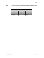
CA-8 Compatible Fixtures
MODEL NUMBER
ILS-625DCR
DMX-100SQ
CH-649X
DMX-100
DMX-100S
CH-610
CH-605
ILS-515DMR
DMX-515R
DMX-1655R
DX-427W
DMX-425
CH-636X
LGG-2050RG
DMX-100B
TFX-900
ST-200X
ILS-606DBR
ILS-606DSR
DMX-606R
MODEL NAME
Colortrack™ 250DCR-ILS
DJ Squeeze™
Explorer Plus™
Fascination™
Imagination™
Insignia™
Intimidator™
Legend™ 150DMR-ILS
Legend™ 150R
Legend™ 250RX
Mini Legend Wash™
Mini Legend™
Navigator Plus™
Orbiter RG™
Sensation™
Stage Wash™ 900
Techno Strobe™ 200X
Trackscan™ 250-ILS (Barrel)
Trackscan™ 250-ILS (Scanner)
Trackscan™ 250R
DMX Primer
There are 512 channels in a DMX-512 connection. Channels may be assigned in any manner. A
fixture capable of receiving DMX 512 will require one or a number of sequential channels. The user
must assign a starting address on the fixture that indicates the first channel reserved in the controller.
There are many different types of DMX controllable fixtures and they all may vary in the total number
of channels required. Choosing a start address should be planned in advance. Channels should
never overlap. If they do, this will result in erratic operation of the fixtures whose starting address is
set incorrectly. You can however, control multiple fixtures of the same type using the same starting
address as long as the intended result is that of unison movement or operation. In other words, the
fixtures will be slaved together and all respond exactly the same.
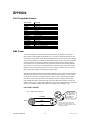
DMX fixtures are designed to receive data through a serial Daisy Chain. A Daisy Chain connection is
where the DATA OUT of one fixture connects to the DATA IN of the next fixture. The order in which
the fixtures are connected is not important and has no effect on how a controller communicates to
each fixture. Use an order that provides for the easiest and most direct cabling. Connect fixtures
using shielded two conductor twisted pair cable with three pin XLR male to female connectors. The
shield connection is pin 1, while pin 2 is Data Negative (S-) and pin 3 is Data positive (S+). CHAUVET
carries 3-pin XLR DMX compliant cables, DMX-10 (33’), DMX-4.5 (15’) and DMX-1.5 (5’)
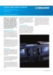
F I XT URE LI NKI NG
Figure 1 - DMX connector configuration
1
3
2
COMMON
INPUT
ILS-CON User Manual
1
3
2
1
3
2
DMX +
DMX -
19
Resistance 120
ohm 1/4w between
pin 2 (DMX -) and
pin 3 (DMX +) of
the last fixture.
OUTPUT
Termination reduces signal errors and to
avoid signal transmission problems and
interference, it is always advisable to connect
a DMX signal terminator.
3/28/2005 3:03:00 PM
Appendix
Note!
If you use a controller with a 5 pin DMX output connector, you will need to use a 5
pin to 3 pin adapter. Chauvet Model No: DMX5M.
The chart below details a proper cable conversion:
3 PIN TO 5 PIN CONVERSION CHART
CONDUCTOR
3 Pin Female (output)
5 Pin Male (Input)
GROUND/SHIELD
Pin 1
Pin 1
DATA ( - )SIGNAL
Pin 2
Pin 2
DATA ( + ) SIGNAL
Pin 3
Pin 3
DO NOT USE
Do not use
DO NOT USE
Do not use
ILS-CON User Manual
20
3/28/2005 3:03:00 PM
Appendix
Maintenance
To maintain optimum performance and minimize wear fixtures should be cleaned frequently. Usage
and environment are contributing factors in determining frequency. As a general rule, fixtures should
be cleaned at least twice a month. Dust build up reduces light output performance and can cause
overheating. This can lead to reduced lamp life and increased mechanical wear. Be sure to power off
fixture before conducting maintenance.
Unplug fixture from power. Use a vacuum or air compressor and a soft brush to remove dust
collected on external vents and internal components. Clean all glass when the fixture is cold with a
mild solution of glass cleaner or Isopropyl Alcohol and a soft lint free cotton cloth or lens tissue. Apply
solution to the cloth or tissue and drag dirt and grime to the outside of the lens. Gently polish optical
surfaces until they are free of haze and lint. Do not to touch the lamp glass when cleaning fixture. Oil
and dirt can cause damage and premature aging of the lamp. In the event that the lamp is touched or
becomes dirty, clean the lamps with an alcohol wipe.
The cleaning of internal and external optical lenses and/or mirrors must be carried out periodically to
optimize light output. Cleaning frequency depends on the environment in which the fixture operates:
damp, smoky or particularly dirty surrounding can cause greater accumulation of dirt on the unit’s
optics. Clean with soft cloth using normal glass cleaning fluid. - Always dry the parts carefully. - Clean
the external optics at least every 20 days. Clean the internal optics at least every 30/60 days.
Returns Procedure
Returned merchandise must be sent prepaid and in the original packing, call tags will not be issued.
Package must be clearly labeled with a Return Merchandise Authorization Number (RA #). Products
returned without an RA # will be refused. Call CHAUVET and request RA # prior to shipping the
fixture. Be prepared to provide the model number, serial number and a brief description of the cause
for the return. Be sure to properly pack fixture, any shipping damage resulting from inadequate
packaging is the customer’s responsibility. CHAUVET reserves the right to use its own discretion to
repair or replace product(s). As a suggestion, proper UPS packing or double-boxing is always a safe
method to use.
Claims
Damage incurred in shipping is the responsibility of the shipper; therefore the damage must be
reported to the carrier upon receipt of merchandise. It is the customer's responsibility to notify and
submit claims with the shipper in the event that a fixture is damaged due to shipping. Any other claim
for items such as missing component/part, damage not related to shipping, and concealed damage,
must be made within seven (7) days of receiving merchandise.
ILS-CON User Manual
21
3/28/2005 3:03:00 PM
Appendix
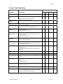
General Troubleshooting
Applies to
Symptom
Solution(s)
Auto shut off
Check fan thermal switch reset
Beam is very dim or not
bright
Clean optical system or replace lamp
Breaker/Fuse keeps
blowing
Check total load placed on device
Chase is too slow
Check users manual for speed adjustment
Device has no power
Check for power on Mains.
Lights
Foggers
& Snow
Controllers
Dimmers
& Chaser
Check 220/110v switch for proper setting
Check device’s fuse. (internal and/or external)
Fixture is not
responding
Check DMX Dip switch settings for correct addressing
Check DMX cables
Check polarity switch settings
Fixture is on but there
is no movement to the
audio
Make sure you have the correct audio mode on the control
switches. If audio provided via ¼” jack, make sure a live
audio signal exists
Adjust sound sensitivity knob
Lamps cuts off
sporadically
Possible bad lamp or fixture is overheating.
Light will not come on
after power failure
Some discharge lamps require a cooling off period before
the electronics in the fixture can kick start it again, wait 5 to
10 minutes before powering up
Loss of signal
Use only DMX cables
Lamp may be at end of its life.
Install terminator
Note: Keep DMX cables separated from power cables or
black lights.
Moves slow
Check 220/110v switch for proper setting
No flash
Re-install bulb, may have shifted in shipping
No laser output
Bounce mirror motor may have shifted during shipping,
readjust
No light output
Check slip ring & brushes for contact
Install bulb
Call service technician
Relay will not work
Check reset switch
Check cable connections
Remote does not work
Make sure connector is firmly connected to device
Stand alone mode
All Chauvet lighting fixtures featuring stand-alone functions
do not require additional settings, simply power the fixture
and it will automatically enter into this mode
ILS-CON User Manual
22
3/28/2005 3:03:00 PM
Appendix
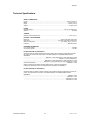
Technical Specifications
WEIGHT & DIMENSIONS
Length ............................................................................................................................ 485 mm (19.09 in)
Width .................................................................................................................................. 135 mm (5.3 in)
Height ................................................................................................................................. 80 mm (3.15 in)
Weight ............................................................................................................................... 2.5 Kg (5.5 lbs)
POWER
Operating Range ...................................................................................................DC 9V-12V 300mA min
Adapter...........................................................................................................................................Provided
THERMAL
Maximum ambient temperature ............................................................................................45°C (113° F)
CONTROL & PROGRAMMING
Data input....................................................................................................locking 3-pin XLR male socket
Data output ....................................................................................... 2 x locking 3-pin XLR female socket
Data pin configuration................................................................................. pin 1 shield, pin 2 (-), pin 3 (+)
Protocols ...........................................................................................................................DMX-512 USITT
ORDERING INFORMATION
ILS™ Control Center .................................................................................................................... ILS-CON
CA-8 Linking Cables .......................................................................................................................CA-CBL
EC DECLARATION OF CONFORMITY
We declare that our products (lighting equipments) comply with the following specification and bears
CE mark in accordance with the provision of the Electromagnetic Compatibility (EMC) Directive
89/336/EEC.
......................................................................EN55014-1: 1993, EN61000-3-2: 1995, EN61000-3-3:1995
................................................................................................................ EN55014-2: 1997 CATEGORY II
.................................................................. EN61000-4-2: 1995, EN61000-4-3: 1995, EN61000-4-4:1995
............................................................... EN61000-4-5: 1995, EN61000-4-6: 1995, EN61000-4-11: 1994
Harmonized Standard..................................................................................................... EN60598-1: 1993
Safety of household and similar electrical appliances Part 1: General requirements
Following the provisions of the Low Voltage Directive 73/23/EEC and 93/68/EEC.
EC DECLARATION OF CONFORMITY
We declare that our products (remote controller) comply with the following specification and bears CE
mark in accordance with the provision of the Electromagnetic Compatibility (EMC) Directive
89/336/EEC.
.............................................................................................................................................EN55015: 1993
......................................................................................................................................... EN50082-1: 1997
...................................................................................................................................... EN61000-3-2: 1995
...................................................................................................................................... EN61000-3-3: 1995
ILS-CON User Manual
23
3/28/2005 3:03:00 PM