1
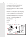
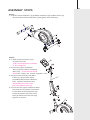
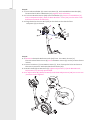
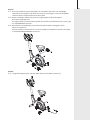
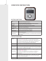
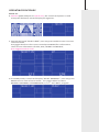
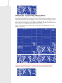
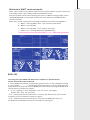
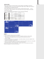
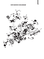
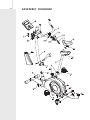
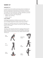
PURE BIKE USER MANUAL
Welcome from Reebok Fitness.
Thank you for choosing this Reebok Pure Exercise Bike.
Before you get started, please read the instructions. Should
you experience any difficulties, our support team will be happy
to help or check out our website at: www.reebokftness.info
Important note:
Consult your doctor before starting any exercise program.
If you feel any sickness, chest pain, fits of dizziness or
breathlessness during your training, stop exercising and
consult your doctor immediately.
If you have any further queries please call or email our
customer support team on the number or email address on
the back of this manual.
Model name:
Reebok Pure Bike
Serial number:
These details can be found on the underside of your product.
01
CONTENTS
Pre-assembly Notes
Assembly Steps
Precautions
06
Computer Operation
09
Maintenance
16
Exploded Diagram
17
Assembly Diagram
18
Parts List
19
Warm Up
21
Limited Warranty
22
02
PRE-ASSEMBLY NOTES
Open The Box
Make sure to inventory all of the parts that are included in the box.
Check the Hardware Chart for a full count of the number of parts
included for proper assembly. If you are missing any parts,
please call our Technical Support line 0800 440 2459
Gather Your Tools
Before starting the assembly of your unit, gather the necessary tools.
Having all of the tools at hand will save time and make the assembly
quick and hassle-free.
Clear Your Work Area
Make sure that you have cleared away a large enough space to properly
assemble the unit. Make sure the space is free from anything that may
cause injury during assembly. After the unit is fully assembled, make
sure there is a comfortable amount of free area around the unit for
unobstructed operation.
Hardware Chart
For your convenience, we have identified the hardware used in the
assembly of this product. This chart is provided to help you identify
those items that may be unfamiliar to you. If you find any parts missing
please contact our Technical Support line 0 800 440 2459 .
14.Allen Head Bolt M10*20
19.Arc Washer Φ8.5*Φ22*T1.5
20.Allen Hard Bolt M8*15
23.ScrewΦ4*20
29.L Shape Knob
Allen key L6
Spanner L15
Box Wrench
20 M8*15-4PCS
19 Ø22*Ø8.5-4PCS
23 Ø4*20-2PCS
29 1 PC
TOOL:
L6-1pc,L13*17-1pc,L15-1pc
14 M10*20-4PCS
4
4
4
2
1
1
1
1
ASSEMBLY STEPS
Step 1:
1-1. Attach Front Stabilizer (2) and Rear Stabilizer (3) to Main frame (1),
fastened with Allen Head Bolts (14) Tighten with Allen Key.
Step 2:
2 -1 : Slide Front Post Cover (11 )
on Front Post (4) .
( Lift it to the position as shown
in the diagram)
2-2: Connect Upper Computer
Wire (15 ) with Lower Computer
Wire (16 ),A click will be heard
when t he cables are locked together fully.
2-4:Insert Front Post (4 ) into Main
frame (1), fasten with Allen
Head Bolt (20) and Arc Washers
(19 ) . Tighten with Allen Key.
Place the Front Post Cover
(11) onto Main Frame (1).
2-5: Connect the Upper Computer Wire
(15 ) with the computer connector
on the back of the Computer (6 ) .
Install Computer (6 ) onto Front
Post (4 ) fasten with Screws (22)
tighten as shown.
03
04
Step 3:
3-1: Secured Handlebar (5) onto Front Post (4), with Handlebar Bracket (26),
fastened with Allen Head Bolt (27),tighten with Allen Key. .
3-2: Fix Front Bracket Cover (28) onto Handlebar (5), Fasten to Handlebar (5)
with L shape Knob (29), Now fix Rear Bracket Cover (24) on the other side
and fastened with Screws(23),
3-3: Plug the Pulse Sensor Wire(25) to the hole on the back of the
computer (6) as shown.
Step 4:
4-1: Remove the Quick Release Knob (10) from the Main Frame (1).
Place the Seat Post Cover (9) onto the Main Frame (1) as the picture shown
below.
4-2: Insert Seat Post (7) into Main Frame (1), then line up the hole and secure
the seat in position with Quick Release Knob (10).
4-3: Attach Seat (8) to Seat Post (7) tighten Nylon Nut (17)with Box Wrench.
Nylon Nut (17) already assembled.
4-4: To adjust Sear (8) (back/forward) undo Seat Adjustment (18) set to correct
position and re-tighten.
Step 5:
5-1:Slot the Pedal Strap on the pedals as marked L and R for left and Right.
the side of the pedal strap with more slots should go on outside of pedal
to allow ease of adjustment at a later date
5-2: Attach the Right Pedal (13) onto the right pedal shaft and tighten
with open end spanner.
The right pedal is marked with R and should be threaded onto the crank (30)
in a CLOCKWISE direction.
5-3: Attach the Left Pedal (12) onto the left pedal shaft and tighten with
open end spanner.
The left pedal is marked with L and should be threaded onto the crank (30)
in a COUNTERCLOCKWISE direction.
Step 6 :
6-1: Plug the Adaptor(21) into the back hole of the Main Frame (1).
05
06
PRECAUTIONS
This product has been designed for in-home use. These instructions are
intended to provide important information for use and maintenance of the
equipment as well as for your personal safety. Keep this user manual safe for
future reference.
WARNING!
This product is made for home use only and tested up to a maximum body
weight of 120 kilograms.
RFE UK Ltd. assumes no responsibility for personal injury or
property damage sustained by or through the use of this equipment. It is
the responsibility of the owner to ensure that all users of this equipment are
adequately informed of all warnings and precautions.
SCOPE
•
Maximum user weight of 120kg.
•
This product is designed for physical exercise by adults. This product is not
suitable for use by persons under 14 years of age.
•
Never allow more than one person on the equipment at a time.
ENVIRONMENT
•
Ensure that those present are aware of possible hazards e.g. moveable
parts during training.
•
Ensure that suffcient space is available to use the exercise bike.
•
Please ensure that liquids or perspiration never enter the machine or
electronics.
•
This product is designed to be used and stored indoors. Do not store the
product outside, or in damp/ dusty environments.
•
The product is made for home use only. Warranty and manufacturer’s
liability do not extend to any product or damage to the product caused by
commercial use.
USER HEALTH
• Consult your doctor before starting any exercise programs to receive advice
on training.
• Incorrect/excessive training can cause health problems or injuries .
• If you feel sickness, chest pain, fits of dizziness or breathlessness during
your training, immediately stop the training and consult your doctor.
PRODUCT PREPARATION
• Ensure the bike is on a flat, level surface with at least 0.5m of clear area
surrounding the exercise bike.
• Ensure that training only starts after correct assembly, adjustment and
inspection of the product.
• Follow the steps of the assembly instructions carefully .
• Only use suitable tools for assembly and ask for assistance if necessary.
• Only use original Reebok parts as delivered).
SAFETY CHECKS BEFORE EVERY USE
• Tighten all adjustable parts to prevent sudden movement while training.
• Tighten all nuts and bolts.
• Check that the saddle is secure.
• Check that the pedals are secure.
• Check that the tension knob is secure.
• Check that the handlebars are secure.
• Press start to ensure there is power to the console.
• Do not use the product without shoes or with loose shoes.
• Be aware of non-fxed or moving parts whilst mounting or dismounting
the product.
• Do not wear loose or poorly ftting clothing that may become trapped in
the product.
07
08
COMPUTER INSTRUCTION
BUTTON FUNCTIONS
UP
DOWN
To make upward adjustment to each function or
increase training resistance.
To make downward adjustment to each function
or decrease training resistance.
MODE
To confirm setting, acts as enter button.
STAR/STOP
To start or stop workout.
RESET
To reset current setting and have the monitor switch to
initial training mode for selection.
RECOVERY
To test heart rate recovery status.
BODY FAT
To test body fat %
Press the BODY FAT button in standby mode and modify
user data.
DISPLAY FUNCTIONS
TIME
SPEED
RPM
DISTANCE
CALORIES
Count up - No preset target, Time will count up from 00:00 to
maximum 99: 00 with each increment being 1 second.
Count down - If training with preset Time, Time will count
down from preset to 00:00. Each preset increment or
decrement is 1 minute between 01:00 to 99:00.
Displays current training speed. Maximum speed is 99.9 KM/H
Displays the Rotation Per Minute. Display range 0~15~999
Accumulates total distance from 00:00 up to 99.90 KM. The
user may preset target distance data by pressing UP/DOWN
button. Each increment is 0.1KM.
Accumulates calories consumption during training from 0 to
maximum 9990 calories.
(This data is a rough guide for comparison of different
exercise sessions which can not be used in medical
treatment.)
PULSE
User may set up target pulse from 0 - 30 to 230, the computer
will beep when your actual heart rate is over the target
set prior to the workout.
WATTS
Display current workout watts. Display range 0~999.
OPERATING PROCEDURE
Power on:
1. Connect power adaptor to rear of unit , the console will power on and
a beep will be heard, LCD will display all segments.
2. Console will show “SELECT USER”, user may press mode to enter into user
selection mode .
Use joggle wheel to select U1 to U4 and press MODE for confirmation.
then set user information for SEX, AGE, HEIGHT and WEIGHT.
User Joggle wheel to scroll.
3 .In standby mode, console will display “SELECT WORKOUT”, user may press
MODE to enter into selection mode. Turn joggle wheel to select
MANUAL PROGRAM , USER PROGRAM , H.R.C.and WATT program
09
10
Workout in MANUAL mode:
In standby mode, select MANUAL and press MODE to enter.
Quick start: User may press START/STOP to start training in MANUAL, all
exercise values will start counting up from zero.
After enter into MANUAL mode, user may set up TIME→DISTANCE→CALORIES→
PULSE→RESISTANCE LEVEL can be set when flashing, press MODE to confirm ,
press START/STOP to start workout.
All values will start counting down to zero. (To clear setting, press RESET button)
In manual mode, biking animation will move forward every 3 km, and PC speed
will be the same as user's speed.
The console will sound a double beep when you have reached preset pulse .
Program select mode - Manual
Quick Start in Manual mode, all value count up from 0
Workout in Manual mode, user may set up value Time setting in Manual mode
and start workout, console will count down to 0.
Distance setting in Manual mode
Pulse setting in Manual mode
Calories setting in Manual mode
Level setting in Manual mode
Workout in PROGRAM mode:
In standby mode, select PROGRAM and press MODE to enter.
Turn joggle wheel up or down to select preferred program from 1 to
12, and press MODE to confirm. Program profile will flash, user may turn up
or down to adjust profile’s resistance level.
TIME is fixed in 20:00, which is not adjustable. Press START/STOP to start
workout and racing with PC.
After start, TIME will start counting down; the runway animation will follow
user’s RPM input.
User need to follow PC speed by checking below symbols to finish the entire
20 minutes training:
▲ : USER speed > PC RPM – user need to slow down
● : USER speed = PC RPM
▼ : USER speed < PC RPM – user need to speed up
When TIME count down to zero, console will beep for 8 seconds, and display
racing result: PC WIN or USER WIN.
11
runway
Workout in User program mode:
In standby mode, select USER PRO and press MODE to enter.
User may create his / her own preferred profile by turning UP and DOWN to set
up resistance level of each row, and press MODE to confirm. To confirm profile press
and hold Mode.Please note during initial profile work out you can change
each section of the profile during the workout session, at the end press
and hold Mode to confirm.
Time is fixed in 20:00, which is not adjustable. User may press START/STOP
button to start workout.
After start, TIME will start counting down; the runway animation will follow
user’s RPM input.
User need to follow PC speed by checking below symbols to finish the entire 20
minutes training: ▲ : USER speed > PC RPM – user need to slow down
● : USER speed = PC RPM
▼ : USER speed < PC RPM – user need to speed up
When TIME count down to zero, console will beep for 8 seconds, and display
racing result: PC WIN or USER WIN.
12
Workout in H.R.C( Heart rate control) mode:
In standby mode, select H.R.C. and press MODE to enter.
AGE 25 is flashing after enter H.R.C. mode, you may set your age by turning
UP/DOWN button and press MODE. The monitor will calculate preset heart
rate value automatically according to your age setting. Screen will show
heart rate percentage 55%, 75%, 90% and TARGET. You may select heart rate
percentage by UP/DOWN/ENTER button for training.
If there is no HR input for 5 seconds, LCD will display “NEED H.R.” until HR
signal is received.
Once you exceed the Target Pulse, the console will sound a double beep,
if you continue pedaling, the resistance will be lowered accordingly,
When the lowest resistance is reached the console will display STOP.
Workout in WATT constant mode:
Note: (This ITEM is not CLASS A Gymnasium product, WATT only for reference)
In standby mode, select WATT and press MODE to enter.
The preset watt value 120 is flashing on screen in WATT setting mode, select
UP/DOWN/ENTER to set target value from 10 to 350. Press START button
to start training.
After start, Level is adjusted according to RPM to reach the setting WATT.
▲ : WATT > setting WATT 25% – user need to slow down
● : WATT = setting 25%
▼ : WATT < setting 25% – user need to speed up
— : WATT > or < setting WATT 50% (OVER SPEC)--Console will sound double beep if ▲ or ▼ below target watts
BODY FAT
You may test your BODY FAT when the computer is in STOP mode.
Please follow the steps as below:
1. Press BODY FAT button, and hold the pulse sensors to start body fat testing.
2. The symbol "- - - - - - - - " will display while testing for a period of 8 seconds.
After 8 seconds, you will see the BODY FAT advice in percentage and BMI and
the fat advice in different symbol.
3. If the reading is not displayed see the error messages
below that may be received.
“E-1" - When you see this indication, it means you did not put your thumb
properly on the conductor. Please try again.
“E-4” - When you see this indication, it means the BODY FAT advice is
exceeded the available area which is fixed in the program.
13
14
After BODY FAT testing, press BODY FAT button to return to the previous
data displayed before testing commenced.
The BODY FAT advice figure and BMI will disappear.
SYMBOL
SEX FAT%
LOW
LOW/MED
MEDIUM
MED/HIGH
MALE
<13%
<13%-25.8%
26%-30%
>30%
FEMALE
<23%
23%-35.8%
36%-40%
>40%
15
RECOVERY:
After exercising for a period of time, keep holding on handgrips and press
“RECOVERY” button. All function display will stop except “TIME” this will start
counting down from 00:60 to 00:00.
Screen will display your heart rate recovery status with the F1,F2….to F6.
F1 is the best, F6 is the worst. User may keep exercising to improve the heart
rate recovery status.
(Press the RECOVERY button again to return the main display.)
Condition
Score
Heart Rate
Excellent
F1
Above 50
Good
F2
40 ~ 49
Average
F3
30 ~ 39
Fair
F4
20 ~ 29
Poor
F5
10 ~ 19
Very Poor
F6
Under 10
NOTE:
1.This computer require 9V, 0.5A adaptor.
2.When user stop pedaling for 4 minutes, computer will enter into power
save mode, all setting and exercise data will stored until user start
exercise again.
3.If the computer does not respond or acts abnormally remove the power lead
completely and then reconnect it.
4.If E2 error message is given on the screen check the cables that were connected
during assembly. These may be loose or disconnected.
Firstly check these connecting cables. If these are all in place please contact
Technical Support for further assistance.
16
MAINTENANCE
Proper maintenance is very important to ensure your equipment is always in
top working condition. Improper maintenance could cause damage or shorten
the life of your equipment as well as exceeding the warranty coverage.
1. Inspect and tighten all parts of the cycle regularly.
• Any worn parts must be replaced immediately.
• Pay particular attention to nuts, bolts, screws and washers.
2. For continued smooth operation ensure the front and rear stabilizers are
fully tightened and kept clean and free from any residue like perspiration or
dust.
3. To ensure all components of the machine (including the frame) are in a
good condition please ensure any perspiration or dust is wiped clean on a
regular basis using a soft, damp cloth.
4. Please don’t use abrasives or solvents as this may afect the colouring or
operation of the components.
5. Check the pedals/footplates are fully tightened before each use.
6. Keep the machine out of direct sun light at all times.
EXPLODED DIAGRAM
17
16
ASSEMBLY DIAGRAM
19
Part List
No.
Part description
Q’y
1
2
3
4
5
6
7
8
9
10
11
12
13
14
15
16
17
18
19
20
21
22
23
24
25
26
27
28
29
30
31
32
33
34
35
36
37
38
39
40
41
42
43
Main Frame
Front Stabilizer
Rear Stabilizer
Front Post
Handlebar
Computer
1
1
1
1
1
1
1
1
1
1
1
1
1
4
1
1
6
1
4
4
1
4
4
1
1
1
1
1
1
2
1
1
4
1
2
1
13
1
1
4
2
2
2
Seat Post
Seat
Seat Post Cover
Quick Release Knob
Front Post Cover
Left Pedal
Right Pedal
Allen Head Bolt M10*20
Upper Computer Wire
Lower Computer Wire
Nylon Nut M8
Seat Adjustment Knob
Arc WasherΦ8.5*Φ22*T1.5
Allen Head Bolt M8*15
Adaptor
Screw M5*10
ScrewΦ4*20
Rear Bracket Cover
Pulse Sensor Wire
Handlebar Bracket
Allen Head Bolt M8*20
Front Bracket Cover
L Shape Knob
Crank
Flat WasherΦ8.5*Φ13*T1.5
Motor
Screw M5*10
Screw M6*30
Pulse Sensor Chip
Philip Screw Φ4*12
Screw Φ5*15
Right Chain Cover
Left Chain Cover
Flange Nut M10X1.25XT6.5
Crank CapΦ23*7
Rear Stabilizer End Cap
Front Transportation Wheel
20
Part List
No.
Part description
44
45
46
47
48
49
50
51
52
53
54
55
56
57
58
59
60
61
62
63
64
65
66
67
68
69
70
71
72
73
74
75
76
77
78
79
80
81
82
83
84
85
86
Nut M6
Seat Post Bushing
Speed Sensor Mount
U Shape Washer
Handlebar Grip
Handlebar End Cap
Drive Belt
Flat WasherΦ8.5*Φ16*T1.5
Bearing 6203Z
Clip Φ17
Drive Wheel
Magnet
Allen Head Bolt M8*34.5
WasherΦ30*Φ34*T0.8
Flywheel Spacer
Pulley
Flywheel
Clip Φ10
Flywheel Axle
Bushing
Tension Rod
Bearing 6900Z
Pulley
Bearing 6003Z
Tension Spring
Magnetic Holder
Bearing 6300Z
Hex Head Bolt M8*60
Wave WasherΦ10.5*Φ14*T0.3
Nut M10xT3.0
Extension Spring
Tension Wheel
Power Wire
Bushing
Seat Slider
Seat Sliding Guide
Carriage Bolt M8*45
Seat Sliding Cover Left
Seat Sliding Cover Right
Nylon Nut M5
Screw M5*62
ScrewΦ4*35
Speed Sensor Wire
Q’y
2
1
1
2
2
2
1
1
2
2
1
1
1
2
1
1
1
1
2
1
1
1
2
1
1
1
1
1
2
1
1
1
1
1
1
1
1
1
1
1
1
1
21
WARM UP
WARMING UP
It is important to warm up before exercising to prepare your body for the
workout it is about to do. The frst phase of a warm up is to increase your
heart rate and get blood pumping around your body faster. Choose an
activity which will warm up the same muscles you are going to use during
your workout, so if you are planning on cycling for 30 minutes, your warm
up could consist of a 5 to 10 minute steady cycle.
• PHASE 1: 5-10 minutes heart raising activity
• PHASE 2: Static stretching
• PHASE 3: Workout
COOL DOWN
Following your workout you should carry out a cool down.
This should gradually bring your heart rate back to a resting level.
To do a cool down perform an activity of your choice at a low
intensity e.g. a steady 5 minute cycle. This should be followed
by static stretches, similar to those in the warm up. Again, hold each
stretch for 30 seconds.
STRETCHES
Hold each stretch for about 30 seconds. Stretching should not hurt;
only stretch your muscles to as far as is comfortable. If you have a
tight or previously injured muscle stretch the afected muscle group
withinthe warm up. Do not perform any sudden movements while
warming up.
Side
Stretch
Arm
Stretch
Groin
Stretch
Hamstring
Stretch
Calf
Stretch
Quad
Stretch
22
LIMITED WARRANTY
RFE UK Ltd warrants products to be free from defective workmanship
and materials, under normal use and service conditions, for the period of 2
years from the date of purchase. Details of these service conditions can be
found within the product’s user manual.
In order to validate warranty dates a proof of purchase is required. This
warranty only extends to the original purchaser and will only be covered
in the country the machine was purchased.
RFE’s obligation under this warranty is limited to replacing or repairing, at RFE’s
discretion, the product through one of its authorised service centres. All repairs
for which warranty claims are made must be pre-authorised by RFE.
This warranty does not extend to any defect caused by abuse, misuse,additions,
modifications or repairs not provided by an RFE authorised service centre.
Products used for commercial or rental purposes and/or used as store display
models are not covered by this warranty. This product is designed for home use.
No other warranty beyond that specifcally set forth above is authorised by RFE.
RFE is not responsible or liable for indirect, special or consequential damages
arising out of or in connection with the use or performance of the product or
damages with respect to any economic loss, loss of property, loss of revenues
or profits, loss of enjoyment or use, costs of removal, installation or other
consequential damages of whatsoever nature.
We advise your product is kept in a room with a constant environment;
preventing your product from being exposed to extremes in temperature,
heat, humidity and moisture. The machine should not be stored in an outbuilding,
shed or covered patio. If stored in a garage ensure this is brick built and secure
from the elements such as damp/cold.
PLEASE RETAIN YOUR RECEIPT AS PROOF OF PURCHASE.
RECYCLE
Reebok products are recyclable. At the end of its useful life please dispose of
this Reebok bike correctly and safely (local refuse sites).
We are committed to providing
complete customer care. If you have any
questions or if your product is damaged,
please contact our trained staff directly via the details below.
CALL TECHNICAL SUPPORT ON 0800 440 2459
OR E-MAIL: [email protected]
or Mail: RFE UK LTD., THE PERFORMANCE CENTRE,
MAIDSTONE RD., KINGSTON,
MILTON KEYNES Mk10 0BD
www.reebokfitness.info.
2010 Reebok UK Ltd. All rights Reserved. ReebokRBK and
the Vector logo
are registered trademarks of Reebok.