1
TERMINAL SLIP PRINTER
MODEL CBM-820
User’s Manual
Declaration of Conformity
This printer conforms to the following Standards:
Low Voltage Directive 73/23/EEC, 93/68/EEC and the EMC Directive 89/336/EEC, 92/31/EEC,
93/68/EEC.
LVD
:
EN60950
EMC
:
:
:
:
EN55022
EN61000-3-2
EN61000-3-3
EN55024
Class B
This declaration is applied only for 230V model.
CITIZEN is a registered trade mark of CITIZEN WATCH CO., LTD., Japan
CITIZEN es una marca registrada de CITIZEN WATCH CO., LTD., Japón
ESC/POS and TM-295 are trademarks of SEIKO EPSON CORPORATION
Auto Side Loading™ is a trademark of Star Micronics Co., Ltd.
Windows codepage is a registered trademark of Microsoft Corporation
IMPORTANT SAFETY INSTRUCTIONS
• Read all of these instructions and save them for future reference.
• Follow all warnings and instructions marked on the product.
• Unplug this product from the wall outlet before cleaning. Do not use liquid or aerosol cleaners.
Use a damp cloth for cleaning.
• Do not use this product near water.
• Do not place this product on an unstable cart, stand or table. The product may fall, causing serious
damage to the product.
• Slots and openings on the back or bottom of the case are provided for ventilation. To ensure reliable
operation of the product and to protect it from overheating, do not block or cover these openings.
The openings should never be blocked by placing the product on a bed, sofa, rug of other similar
surface. This product should never be placed near or over a radiator or heater. This product should
not be placed in an built-in installation unless proper ventilation is provided.
• This product should be operated from the type of power source indicated on the marking label. If
you re not sure of the type of power available, consult your dealer or local power company.
• Do not allow anything to rest on the power cord. Do not place this product where the cord will be
walked on.
• If an extension cord is used with this product, make sure that the total of the ampere ratings of the
products plugged into the extension cord does not exceed the extension cord ampere rating. Also,
make sure that the total of all products plugged into the wall outlet does not exceed 15 amperes.
• Never push objects of any kind into this product through cabinet slots as they may touch dangerous
voltage points or short out parts that could result in a risk of fire or electric shock. Never spill liquid
of any kind on the product.
• Except as explained elsewhere in this manual, do not attempt to service this product by yourself.
Opening and removing the covers that are marked “Do Not Remove” may expose you to dangerous
voltage points or other risks. Refer all servicing on those compartments to service personnel.
• Unplug this product from the wall outlet and refer servicing to qualified service personnel under
the following conditions:
A. When the power cord or plug is damaged or frayed.
B. If liquid has been spilled into the product.
C. If the product has been exposed to rain or water.
D. If the product does not operate normally when the operating instructions are followed. Adjust
only those controls that are covered be the operating instructions since improper adjustment of
other controls may result in damage and will often require extensive work by a qualified
technician to restore the product to normal operation.
E. If the product has been dropped or the cabinet has been damaged.
F. If the product exhibits a distinct change in performance, indicating a need for service.
• Please keep the poly bag which this equipment is packed in away from children or throw it away to
prevent children from putting it on. Putting it on may cause suffocation.
WICHTIGE SICHERHEITSANWEISUNGEN
• Lesen Sie die nachfolgenden Anweisungen sorgfältig durch und bewahren Sie sie auf.
• Befolgen Sie alle auf dem Drucker vermerkten Hinweise und Anweisungen. Vor dem Reinigen
grundsätzlich Stecker aus der Steckdose ziehen. Keine Flüssigkeiten oder Aerosolreiniger
benutzen. Nut mit einem feuchten Tuch abwischen.
• Der Drucker darf nicht in der Nähe von Wasser aufgestellt werden.
• Drucker nicht auf einem unstabilen Wagen, Stand oder Tisch aufstellen. Der Drucker könnte
herunterfallen und dabel beschädigt werden.
• Schlitze und Öffnungen im Gehäuse, in der Rückwand und im Boden dienen der Belüftung. Sie
dürfen keinesfalls zugedeckt oder blockiert werden, da sich der Drucker sonst überhitzt. Drucker
nicht auf ein Bett, Sofa, Teppich oder dergleichen stellen. Drucker nicht in der Nähe eines
Heizkörpers aufstellen. Drucker darf nicht eingebaut werden, falls nicht für ausreichende
Belüftung gesorgt ist.
• Drucker nur mit der auf dem Typschild angegebenen Spannung betreiben. Wenn Sie sich nicht
sicher sind, fragen Sie ihren Händler oder ihr zuständiges Elektrizitätswerk.
• Nichts auf das Stromanschlußkabel stellen. Kabel muß so verlegt werden, daß man nicht
darauftreten kann.
• Ein etwaiges Verlängerungskabel muß der Stromstärke aller daran angeschlossenen Geräte
entsprechen.
• Keine Gegenstände in die Gehäuseschlitze schieben.
• Drucker darf nur da gewartet werden, wo im Handbuch angegeben, Öffnen und. Abnehmen von
Abdeckungen, die mit “Do not remove” gekennzeichenet sind, könnte gefährliche spannungführende Stellen oder sonstige Gefahrenpunkte freilegen. Die Wartung solcher Stellen darf
grundsätzlich nur von besonders ausgebildetem Fachpersonal vorgenommen werden.
A. Wenn das Stromanschlußkabel oder der Stecker beschädigt oder durch-gescheuert ist.
B. Wenn Flüssigkeit auf dem Drucker verschüttet wurde.
C. Wenn der Drucker im Regen gestanden hat oder Wasser darauf verschüttet wurde.
D. Wenn der Drucker trotz genauer Befolgung der Betriebsvorschriften nicht richtig arbeitet. Nur
die in der Bedienungsanleitung angegebenen Einstellungen vornehmen. Ein Verstellen anderer
Bedienungselemente könnte den Drucker beschädigen und macht umständliche Arbeiten eines
qualifizierten Technikers erforderlich, um den Drucker Wieder auf den normalen Betrieb
einzustellen.
E. Wenn der Drucker heruntergefallen ist oder das Gehäuse beschädigt wurde.
F. Wenn der Drucker in seiner Leistung nachläßt.
• Bitte halten Sie den Kunststoffbeutel, in den die Ware verpackt ist, von Kindern entfernt, oder
werfen Sie ihn weg, damit er nicht in die Hande von Kindern gerät. Das Überstülpen des Beutels
kann zum Ersticken führen.
Lärmemission kleiner 70 dBA
IMPORTANT: This equipment generates, uses, and can radiate radio frequency energy and if not
installed and used in accordance with the instruction manual, may cause interference to radio
communications. It has been tested and found to comply with the limits for a Class A computing
device pursuant to Subpart J of Part 15 off FCC Rules, which are designed to provide reasonable
protection against such interference when operated in a commercial environment. Operation of this
equipment in a residential area is likely to cause interference, in which case the user at his own
expense will be required to take whatever measures may be necessary to correct the interference.
CAUTION: Use shielded cable for this equipment.
Sicherheitshinweis
Die Steckdose zum Anschluß dieses Druckers muß nahe dem Grät angebracht und leicht zugänglich
sein.
For Uses in Canada
This digital apparatus does not exceed the class A limits for radio noise emissions from digital,
apparatus, as set out in the radio interference regulations of the Canadian department of
communications.
Pour L’utilisateurs Canadiens
Cet appareil numérique ne dépasse pas les limites de carégorie a pour les émissions de bruit radio
émanant d'appareils numériques, tel que prévu dans les réglements sur l'interférence radio du
départment Canadien des communications.
< CAUTIONS >
1. Prior to using the equipment, be sure to read this User’s Manual thoroughly. Please keep it handy for
reference whenever it may be needed.
2. The information contained herein may be changed without prior notice.
3. Reproduction of part or all of this User’s Manual without permission is strictly prohibited.
4. Never service, disassemble, or repair parts that are not mentioned in this User’s Manual.
5. Note that we will not be responsible for damages attributable to a user’s incorrect operation/ handling or
an improper operating environment.
6. Operate the equipment only as described in this User’s Manual; otherwise accidents or problems may
result.
7. Data are basically temporary; they cannot be stored or saved permanently or for a long time. Please note
that we will not be responsible for damages or losses of profit resulting from losses of the data
attributable to accidents, repairs, tests, and so on.
8. If you have any questions or notice any clerical errors or omissions regarding the information in this
manual, please contact our office.
9. Please note that, notwithstanding Item 8 above, we will not be responsible for any effects resulting from
operation of the equipment.
SAFETY PRECAUTIONS ----- BE SURE TO OBSERVE
In order to prevent hazards to an operator or other persons and damage to property, be sure to observe the
following precautions.
● The following describes the degrees of hazard and damages that can occur if the given instructions are
neglected or the equipment is incorrectly operated.
WARNING
Negligence of this precaution may result in death or serious injury.
CAUTION
Negligence of this precaution may result in injury or damage to
property.
This is an illustration mark used to alert your attention.
This is an illustration mark used to indicate such information as an instruction or the like.
WARNING
● Never handle the equipment in the following manners, as it may break, become out of order, or
overheat causing smoke and resulting in fire or electric shock.
If the equipment is used in an abnormal condition, such as when broken, then problems, smoke
emission, abnormal odor/noise, and fire can result. If an abnormal condition exists, be sure to
disconnect the power plug from a plug socket, and contact our dealer. Never repair the equipment
•
•
•
•
•
•
•
•
•
•
on your own - it is very dangerous.
Do not allow the equipment to receive a strong impact or shock, such as kicking, stomping, hitting,
dropping, and the like.
Install the equipment in a well-ventilated place. Do not use it in such a manner that its ventilation
port will be blocked.
Do not install the equipment in a place like a laboratory where chemical reactions are expected, or
in a place where salt or gases are contained in the air.
Do not connect/disconnect a power cord or a data cable, while holding the cable. Do not pull,
install, use, or carry the equipment in such a manner that force will be applied to the cables.
Do not drop or insert any foreign substances, such as clips or pins, into the equipment.
Do not spill any liquid or spray any chemical-containing liquid over the equipment. If any liquid
is spilled on it, turn off the power, disconnect the power cable and power cord from the plug socket,
and so on, and contact our dealer.
Never disassemble or remodel the equipment. Negligence of this may cause fire or electric shock.
Use the equipment only with the specified commercial power supply and AC adapter. Negligence
of this may result in fire, electric shock, or problems.
If you drop or break the AC adapter, or if water or the like gets inside it, unplug it immediately from
the socket and contact your dealer.
Do not damage, break, process, bend/pull by force, twist, or head an AC adapter cord. Also, do not
put a heavy substance on it or heat it. The AC adapter cord could be broken, resulting in fire,
electric shock, or trouble. If the AC adapter cord is damaged, contact our dealer.
• Do not connect/disconnect the AC adapter with wet hands.
• Do not overload a single electrical outlet, using a table tap or a current tap socket.
● An equipment packing bag must be discarded or kept away from children. A child can suffocate
if the bag is placed over the head.
PRECAUTIONS FOR INSTALLATION
• Do not use or store the equipment in a place exposed to fire, moisture, or direct sunshine, or in a
place near a heater or thermal device where the prescribed operating temperature and humidity are
not met, or in a place exposed to much oil, iron powder, or dust. The equipment may become out
of order, emit smoke, or catch fire.
• Do not install or use the equipment in a place like a laboratory where chemical reactions are
expected, or in a place where salt or gases are contained in the air. There is a danger of fire or
electric shock.
• Install the printer on a flat, stable desk or table that is free from vibration, in a well-ventilated place.
• Do not install the printer at a location where its operation could be hindered.
• Do not place anything on the printer or leave small objects, like a clip or pin, around it. A foreign
object could cause trouble if it gets inside.
• Do not use any sharp-pointed object, such as a pen, for example, to touch the operation panel of the
printer. It could cause trouble.
• Do not use the equipment near a radio or TV receiver. Do not share the power from a plug socket
a radio or TV receiver is connected to. It may cause a reception problem.
• Use the equipment only at the specified power supply, voltage and frequency. Otherwise, it may
emit smoke and catch fire or cause other problems.
• Connect only the specified power source. Use of an unspecified power source could cause trouble
or smoke/fire.
• Confirm that a plug socket used for connection has sufficient capacity.
• Avoid connecting a power cable to a plug socket shared by other devices or extending the wiring
too far. It may result in the cable catching fire or a power outage. Also, do not step on or apply an
excessive force (Pull, load) to the cable, and do not use the printer with such a force applied to it.
• Never connect a grounding cable (Frame ground) to a gas pipe. There is a danger of explosion.
When connecting or disconnecting the grounding cable, be sure to disconnect the power cable and
the power plug from the plug socket.
• When connecting/disconnecting the cables, be sure to turn off the power first, including the
connected side, and then connect/disconnect them, holding a plug and a connector. Pulling the
cable itself could cause it to snap or become damaged.
• Connect a power cable or a connector cable securely. If a reverse-polarity connection is made,
internal elements may be broken or a mating device may be adversely affected.
• Use a shielding wire or twisted pair wire for a signal line, in order to minimize noise effect. Do not
route the cable too long or connect it to a noisy device. Connection to a noisy device could cause
erroneous printing due to corrupt data, and so on.
• Use the equipment in an environment where there is a plug socket near the main body and you can
easily disconnect the power plug from it, to shut off the power.
• When the equipment will not be used for a long period of time, unplug it and remove the paper roll
from it.
• When transporting the equipment, remove the paper roll from the paper holder.
PRECAUTIONS FOR HANDLING
Do not handle the equipment in the following manners, because problems may result.
• Do not use any other power source besides the accessory AC adapter. Also, do not use the AC
adapter for other purposes.
• Do not print without paper.
• Do not drop or put any foreign object, such as a clip, pin, or the like, inside the printer.
• Do not spill any liquid or spray any chemical-containing liquid over the equipment.
• Never use a pointed object, such as a pen, to operate the operation panel.
• Do not use Scotch tape to fasten paper together for continuous use. It could damage the printing
head.
• Never pull the set paper forcibly. When opening/closing the printer cover, take care that the paper
will not be caught. It could cause the paper to jam.
• Be sure to use the specified paper. Use of other paper could deteriorate the print quality or cause a
problem with the printing head.
To Prevent Injury and Spreading of Damage
• Never touch the printing head, motor, or paper cutting blade. Your finger may be cut.
• During power-on or immediately after printing, do not touch electrical parts or moving parts, such
as the mechanism, motor, internal gear, etc. They may be very hot and can burn your hand/finger.
• Be careful to avoid bodily injure or damaging other objects with an edge of sheet metal.
• Should any error occur while operating the equipment, stop it immediately and disconnect the
power plug from the plug socket.
• Only a qualified serviceman is allowed to disassemble or repair the printer.
• Should a problem occur, leave solving it to our serviceman. Do not disassemble the equipment on
your own.
• When opening/closing the printer cover, and so on, be careful not to catch your hand or finger on
the equipment.
• After using the equipment, turn off the power switch and unplug the AC adapter from a plug socket.
DAILY MAINTENANCE
• At the time of maintenance, be sure to turn off the power switch of the printer and unplug it from
the socket.
• Use a dry soft cloth to wipe off stains and dust from the surfaces of the main body case. For severe
soiling, dip the cloth in water and wring it, for wiping off the soil. Never use organic solvents, such
as alcohol, thinner, trichlene, benzene, ketone, or chemical dusters.
• If the equipment is contaminated with paper powder, use a soft brush to clean it. Be careful not to
damage the printing head.
CAUTION :
The printing head and motor are very hot. Be careful not to touch them
immediately after printing. Do not touch the heating surface of the head
with a bare hand or metal.
CONTENTS
1. Printer Setup....................................................................................................................1
1.1 Choosing a place for the printer.............................................................................1
1.2 Unpacking the printer ............................................................................................2
1.3 Removing the protective materials ........................................................................3
2. Specifications ...................................................................................................................4
2.1 General Specifications ...........................................................................................4
2.2 Printing Specifications...........................................................................................5
2.3 Paper Specifications and Print Area ......................................................................5
2.4 Power Supply Specifications .................................................................................7
3. Outer Appearance and Component Parts ....................................................................8
3.1 General guide.........................................................................................................8
4. Operation .........................................................................................................................9
4.1 Removing the printer cover ...................................................................................9
4.2 Installing the ribbon cassette..................................................................................9
4.3 Removing the ribbon cassette ..............................................................................11
4.4 Connecting to a power outlet and turning power on and off ............................... 11
4.5 Connecting to your host computer.......................................................................13
4.6 Connecting to a peripheral unit............................................................................15
4.7 Inserting the paper into the printer.......................................................................16
4.8 AutoSide Loading™ ............................................................................................17
4.9 Control Panel Operations.....................................................................................19
4.9.1 Indicator lights..............................................................................................19
4.9.2 Buttons .........................................................................................................19
4.9.3 Producing a test print....................................................................................20
4.9.4 Adjusting the dot alignment .........................................................................20
4.9.5 Hexadecimal dump.......................................................................................22
4.9.6 Errors............................................................................................................23
4.10 Paper Sensors.......................................................................................................24
5. Making DIP Switch Settings.........................................................................................25
5.1 Accessing the DIP switches.................................................................................25
5.2 Available DIP switch settings..............................................................................27
5.3 Memory Switch Settings......................................................................................28
6. Interface .........................................................................................................................29
6.1 Pins and Signal Names ........................................................................................29
6.2 Interface Connections ..........................................................................................30
7. Peripheral Unit Driver Circuit.....................................................................................31
7.1 Modular plug........................................................................................................31
7.2 Drive circuit .........................................................................................................32
8. Maintenance and Service..............................................................................................33
9. Print Control Functions................................................................................................34
9.1 List of ESC/POS Commands...............................................................................34
9.2 Command Details ................................................................................................36
9.2.1 Description of Each Items ............................................................................36
9.2.2 Command Details.........................................................................................37
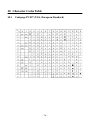
10. Character Codes Table .................................................................................................76
10.1 Codepage PC437 (USA, European Standard)................................................... 76
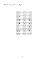
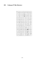
10.2 Codepage Katakana (Japanese) .........................................................................77
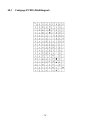
10.3 Codepage PC850 (Multilingual) .......................................................................78
10.4 Codepage PC860 (Portuguese)..........................................................................79
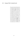
10.5 Codepage PC863 (Canadian-French)................................................................ 80
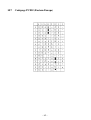
10.6 Codepage PC865 (Nordic) ................................................................................81
10.7 Codepage PC852 (Eastern Europe)...................................................................82
10.8 Codepage PC866 (Russian)...............................................................................83
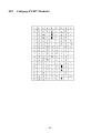
10.9 Codepage PC857 (Turkish) ...............................................................................84
10.10 Windows Codepage...........................................................................................85
10.11 Codepage PC858 (Multilingual+Euro) ............................................................. 86
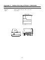
Appendix 1: Outline Drawing of Printer (CBM-820) .................................................... 87
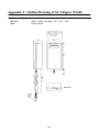
Appendix 2: Outline Drawing of AC Adapter (31AD) .................................................. 88
<<< German >>>
1. Drucker-Einrichtung ....................................................................................................96
1.1 Wahl eines Aufstellungsorts für den Drucker...................................................... 96
1.2 Auspacken des Druckers......................................................................................97
1.3 Entfernen der Schutzmaterialien..........................................................................98
2. Technische Daten...........................................................................................................99
2.1 Allgemeine Daten ................................................................................................99
2.2 Druckspezifikationen .........................................................................................100
2.3 Papier-Spezifikationen und Druckbereich ......................................................... 100
2.4 Technische Daten zur Netzversorgung .............................................................. 102
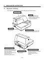
3. Außenansicht und Bauteile.........................................................................................103
3.1 Allgemeine Anleitung........................................................................................103
4. Betrieb ..........................................................................................................................104
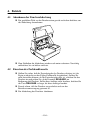
4.1 Abnehmen der Druckerabdeckung ....................................................................104
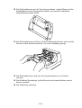
4.2 Einsetzen der Farbbandkassette .........................................................................104
4.3 Entnehmen der Farbbandkassette ......................................................................106
4.4 Anschluß an eine Netzsteckdose und Ein-/Ausschalten der Netzversorgung ... 106
4.5 Anschließen an den Hostcomputer ....................................................................108
4.6 Anschluß an ein Peripheriegerät ........................................................................110
4.7 Papier in den Drucker einlegen..........................................................................111
4.8 Automatischer Papiereinzug (AutoSide Loading™) ......................................... 112
4.9 Bedienfeld ..........................................................................................................114
4.9.1 Anzeigeleuchten .........................................................................................114
4.9.2 Tasten .........................................................................................................115
4.9.3 Erstellen eines Testdrucks..........................................................................115
4.9.4 Einstellen der Punktausrichtung.................................................................115
4.9.5 Sedezimaler Datenausdruck .......................................................................117
4.9.6 Fehler..........................................................................................................118
4.10 Papiersensoren ...................................................................................................119
5. DIP-Schaltereinstellung ..............................................................................................120
5.1 Zugang zu den DIP-Schaltern............................................................................120
5.2 Verwendbare DIP-Schaltereinstellungen........................................................... 122
5.3 Einstellen der Speicherschalter..........................................................................123
6. Schnittstelle ..................................................................................................................124
6.1 Stifte und Signalnamen......................................................................................124
6.2 Schnittstellenanschlüsse.....................................................................................125
7. Treiberschaltung für periphere Einheiten................................................................ 126
7.1 Modularstecker ..................................................................................................126
7.2 Treiberschaltung ................................................................................................127
8. Wartung und Dienst....................................................................................................128
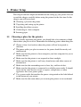
1. Printer Setup
This chapter contains important information on setting up your printer. Be sure
to read this chapter carefully before using the printer for the first time. In this
chapter you will learn about:
❏
❏
❏
❏
❏
Choosing a place for the printer
Unpacking and setting up the printer
Installing the ribbon cassette
Connecting to a host computer
Inserting paper
1.1 Choosing a place for the printer
Before actually unpacking the printer, you should take a few minutes to think
about where you plan to use it. Remember the following points when doing this.
✓ Choose a firm, level surface where the printer will not be exposed to
vibration.
✓ The power outlet you plan to connect to for power should be nearby and
unobstructed.
✓ Make sure that the printer is close enough to your host computer for you to
✓
✓
✓
✓
✓
✓
connect the two.
Make sure that the printer is not exposed to direct sunlight.
Make sure that the printer is well away from heaters and other sources of
extreme heat.
Make sure that the surrounding area is clean, dry, and free of dust.
Make sure that the printer is connected to a reliable power outlet. It should
not be on the same electric circuit as copiers, refrigerators, or other
appliances that cause power spikes.
Use a power outlet that matches the power rating noted on the label affixed
to the bottom of your printer.
Make sure that the room where you are using the printer is not too humid.
–1–
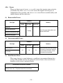
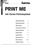
1.2 Unpacking the printer
Check to make sure that the carton contains each of the items shown in the
following illustration.
Printer
Ribbon cassette
User’s Manual
Ferrite core
Fastener
AC Cable
AC Adapter
Notes of the AC adapter
Note:
The AC adapter is accompanied by Notes. Be sure to read this document prior
to using the AC adapter, and keep it together with this manual.
If anything is missing, contact the dealer where you bought the printer and ask
them to supply the missing part. Note that it is a good idea to keep the original
box and all the packing materials just in case you need to pack the printer up
again and send it somewhere at a later date.
Always keep the Instruction Manual and Notes near the printer, for ready
reference whenever necessary.
–2–
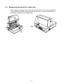
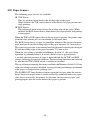
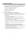
1.3 Removing the protective materials
Four protective materials are inserted into the printer to protect components
during shipping. Before using the printer, be sure to remove all protective
materials as shown in the illustration.
tape
tape
–3–
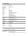
2. Specifications
2.1 General Specifications
Printing System
Number of Head Pins
Printing Speed
Number of Print Columns
Total dots
Printing width
Dot spacing
Paper Width
Sensors
Command Modes
Interface
Data Buffer
Reliability
Operating Environment
Temperature
Humidity
Storage Environment
Temperature
Humidity
Reliability
Printable lines
Head life
Ink Ribbon
Type
Serial impact dot-matrix
9 wires
3.1 lines/sec maximum
35
210
63 mm
Horizontal: 0.30mm
Vertical: 0.35mm
80mm to 182mm
Paper out top-of-form, bottom-of-form sensors
ESC/POS mode (TM-295 emulation)
Serial (RS-232C standard)
2 K bytes / 35 bytes
(Can be selected by DIP switch)
Mechanism (MCBF): 2.5 million lines
Printer head life: 70 million characters
41°F to 104°F (5°C to 40°C)
10% to 80% RH at 40°C (non-condensing)
-4°F to 140°F (-20°C to 60°C)
5% to 90% RH at 40°C (non-condensing)
MCBF 2,500,000 lines
70,000,000 characters
Cartridge cassette
Color
Purple
Ribbon Material
Nylon # 40 denier
Life
2.2 million characters
Important!
Use only the specified type of ribbon. Use of another type of ribbon can cause
malfunction of and damage to the printer.
Applicable Standards
115 V model: UL, C-UL, FCC Class-A
230 V model: TÜV, CE Marking
✳Those standards are applicable when our exclusive AC adapter (31AD series) is used.
–4–
2.2 Printing Specifications
Character Set
Character Matrix
Character Dimensions
Codepage PC437 (USA, European Standard)
Codepage Katakana (Japanese)
Codepage PC850 (Multilingual)
Codepage PC860 (Portuguese)
Codepage PC863 (Canadian-French)
Codepage PC865 (Nordic)
Codepage PC852 (Eastern Europe)
Codepage PC866 (Russian)
Codepage PC857 (Turkish)
Windows Codepage
Codepage PC858 (Multilingual+Euro)
7 × 9 (half), 42 columns
5 × 9, 35 columns
7 × 9 font (half): 1.2 (W) × 2.42 (H) mm
5 × 9 font (2 pulses per dot): 1.5 (W) × 2.42 (H) mm
5 × 9 font (3 pulses per dot): 2.1 (W) × 2.42 (H) mm
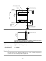
2.3 Paper Specifications and Print Area
Paper Width
Paper Length
Copies
Paper Thickness
Copy Offset
Binding
Print Area
80 to 182mm / 3.15″ to 7.17″
80 to 257mm / 3.15″ to 10.8″
Original + 2
1-ply: 0.09 to 0.2mm / 0.0035″ to 0.0079″
Duplicates
0.12 mm (minimum for 2-ply forms) to 0.25 mm/0.0047 ″ to 0.0098″
<Maximum 0.2 mm when printing graphics>
1.5mm maximum/15 lines (between top sheet and bottom sheet)
Top or left
Distance from first printed line (Head #1) to top of form (form stopper):
28.6 mm
Distance from first printed line (Head #1) to TOF sensor:
26.0 mm
(However, with the automatic start position operation, this distance is set to 26.5 mm.
The automatic start position operation can be enabled or disabled with the memory
switches.
When the top-of-form sensor is disabled, a command can be used to perform a reverse
paper feed enabling printing to begin at approximately 20 mm from the top of the paper.)
Distance from last printed line (Head #9) to bottom of form (BOF sensor):
38.1 mm
(Printing may continue to 27.3 mm from the bottom of the paper.)
When the BOF sensor is disabled, printing can continue to 14.0 mm from the bottom of
the paper.
Right margin:
5.1 mm
Print area width:
62.7 mm
–5–
Form stopper (fixed)
3.2
TOF sensor (fixed)
Paper
26.0
5.1
62.7
28.6
Head #1
Paper feed direction
2.82
First printed line
11.9
Head #9
38.1
14
Last printed line
Paper feed
roller
BOF sensor (fixed)
3.2
Print Position
8 mm
No holes in this area
Paper feed
direction
Do not use paper with perforations within the shaded area. Perforations may cause the
paper sensor to erroneously report an out of paper condition.
Paper Feed
Drive
Stepping motor
Pitch
Speed (while printing)
Adjustable in n/60″ units (approximate)
3.5″ per second
Speed (while ejecting)
4.5″ per second
Important!
Slip paper must be flat, smooth, and free of curls, bends, wrinkles and folds, all
of which can cause jamming and soiling by ink.
–6–
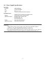
2.4 Power Supply Specifications
Power Supply
AC Adaptor
Input
Output
Plug
31AD, switching type
AC100 to 240V 50/60Hz
DC 24V ± 5%, 1.9A
TCP8927-83-1100 (Hoshiden brand or equivalent.)
Consumption Current
Conditions: DC 24V, excluding external equipment driving
Operating
(approximate averages)
Stand-by
(approximate averages)
Continuous ASCII printing + paper feed: 0.6A
Solid block printing + paper feed: 1.0A
Solid block printing: 1.9A
Peak (solid printing): 3.1A
Paper release deactivated: 0.24 A
Paper release activated: 0.07A
Important!
• When using a printer power supply other than the specified AC adaptor
(31AD), be sure that the following cautions are observed.
• Use a power supply of DC 24 V ±5% and more than 1.9 A.
• Be careful about installing the printer in an area where there is noise. Take the
appropriate measures to protect against electrostatic AC line noise, etc.
–7–
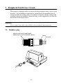
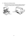
3. Outer Appearance and Component Parts
3.1 General guide
The following illustrations describe the major components, buttons, and
connectors of your printer.
Printer cover
Protects internal components.
Control panel
Three indicators show
the printer status, and
two switches provide
control over printer
functions.
Power switch
Turns printer
power on and off.
Peripheral unit connector cover
Covers a modular jack for
connection of a cash drawer or
other peripheral.
Do not connect a telephone line
to this connector.
Document table
Supports the paper fed
into the printer.
Interface connector
For connection
to a host computer.
–8–
AC adapter cable connector
For connection of the AC adapter.
Never unplug the AC adapter
while the printer is on.
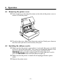
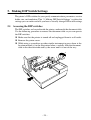
4. Operation
4.1 Removing the printer cover
❏ Push straight up on the ridged locations on the sides of the printer cover to
remove it from the printer.
❏ To replace the cover, slide it back down into position. Gently press down on
the cover until you hear it click securely into place.
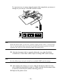
4.2 Installing the ribbon cassette
❏ Make sure that the printer's paper release is activated (the paper is not held
in place by the paper feed roller). If it cannot be determined whether or not
the paper release is activated, turn on the printer and check if the
RELEASE indicator on the control panel is lit. If the indicator is not lit,
press the RELEASE button until the indicator lights up.
❏ Make sure that the printer is turned off and unplugged from its power
outlet.
❏ Remove the printer cover.
–9–
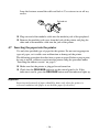
❏ Remove the ribbon cassette from its packaging, and turn its knob in the
direction indicated by the arrow to take up any slack in the ribbon.
❏ Holding the ribbon cassette so that the ribbon is facing down, install the
cassette into the slip printer as shown in the illustration.
❏ Press gently but firmly on the cassette until it snaps securely into place.
❏ Rotate the knob on the cassette again to take up any slack.
❏ Replace the printer cover.
– 10 –
4.3 Removing the ribbon cassette
Use the following procedure to remove the ribbon cassette from the slip printer
when you want to replace it with a new one.
❏ Make sure that the printer is turned off and unplugged from its power
outlet.
❏ Remove the printer cover.
❏ Grasping the ribbon cassette as shown, gently pull it away from the printing
mechanism.
❏ Use the procedure under “Installing the ribbon cassette” on page 9 to install
a new cassette.
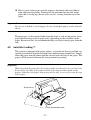
4.4 Connecting to a power outlet and turning power on and off
❏ Make sure that the printer is turned off.
❏ Plug the AC adapter that comes with the printer into the printer’s AC
adapter cable connector.
❏ Connect a three-prong grounded power cord to the power cord connector of
the AC adapter.
Note:
The printer does not come with a power cord, so you must provide one yourself.
– 11 –
❏ Plug the other end of the power cord to a standard household wall outlet.
❏ Use the power switch on the left side of the printer to turn power on and off.
Important!
We recommend that you unplug the printer from the power outlet whenever you
do not plan to use it for long periods. Because of this, you should locate the
printer so that the power outlet it is plugged into is nearby and easy to access.
At this point you may want to perform a test of the printer to make sure it is
working properly. See page 20 for details on how to test the printer.
– 12 –
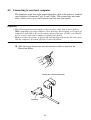
4.5 Connecting to your host computer
The computer sends data to the printer through a cable to the printer’s standard
serial interface (Connector Type: D-sub 25-pin). This printer does not come
with a cable, so it is up to you to obtain one that suits your needs.
Important!
• The following instructions apply to the interface cable that is used with an
IBM-compatible personal computer. Note that they do not apply to all types of
computers and cables. If you are unsure about what type of cable you should
use to connect with your computer, consult your dealer.
• Make sure that the printer is turned off and unplugged from the AC outlet and
that the computer is turned off before connecting them.
❏ Affix the larger ferrite core onto the interface cable as shown in the
illustration below.
Ferrite core (28 mm diameter)
Cable
Interface
– 13 –
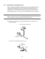
Pass the fastener through the ferrite core.
5 cm
maximum
Fastner
Loop the fastener around the cable and lock it. Use scissors to cut off any
excess.
Pull and cut
❏ Plug one end of the serial cable into the serial port of your computer, and
the other end of the cable into the socket on the back of the printer. Secure
both connectors in place with the screws that are provided.
– 14 –
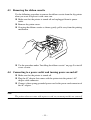
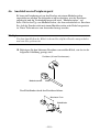
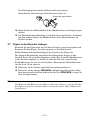
4.6 Connecting to a peripheral unit
You can connect a peripheral unit to the printer using a modular plug. The
following describes how to install the ferrite core and make the actual
connection. See “Modular plug” on page 31 for details about the type of
modular plug that is required. Note that this printer does not come with a
modular plug or wire, so it is up to you to obtain one that suits your needs.
Important!
Make sure that the printer is turned off and unplugged from the AC outlet and
that the computer is turned off before making connections.
❏ Affix the smaller ferrite core onto the modular wire as shown in the
illustration below.
Ferrite core (20 mm diameter)
Connector Cable
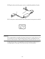
Pass the fastener through the ferrite core.
5 cm
maximum
Fastner
– 15 –
Loop the fastener around the cable and lock it. Use scissors to cut off any
excess.
Pull and cut
❏ Plug one end of the modular cable into the modular jack of the peripheral.
❏ Remove the modular jack cover from the back of the printer and plug the
other end of the modular cable into the jack of the printer.
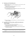
4.7 Inserting the paper into the printer
Use only the specified type of paper for this printer. Do not use inappropriate
types of paper, or it could cause malfunction or damage of the printer.
The following procedure describes how to print on paper. Before trying to print,
be sure to install a ribbon cassette into the printer using the procedure under
“Installing the ribbon cassette” on page 9.
❏ Make sure that the printer is plugged in and turned on.
❏ Check that the RELEASE indicator on the control panel is lit. If the
indicator is not lit, press the RELEASE button until the indicator lights up.
Important!
Insertion and removal of paper should be done only when the printer is
released condition (the paper is not held by paper feed roller).
– 16 –
❏ Place a piece of the paper onto the printer’s document table and slide its
right edge into the printer. Printing will be performed on the side of the
paper that is facing up (the one you can see), starting from the top of the
paper.
Important!
Do not use wrinkled or curled paper. In case of multiple paper, neatly align the
sheets.
Though paper can be inserted either from the front or side of the printer, front
paper insertion may result in paper jams, depending on the condition of the
paper. Because of this, it is recommended that you always insert paper from the
side.
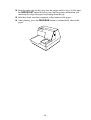
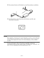
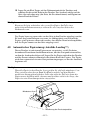
4.8 AutoSide Loading™
This printer is equipped with paper sensors, so you do not have to perform any
special procedure to align the location from which printing should start. Simply
insert the paper into the printer and the sensor locates the top of the paper. The
paper will be moved automatically into position for printing.
Important!
When inserting the paper into the printer, make sure that there are at least 3 cm
between the top edge of the paper and the print start position mark on the
printer. Otherwise the paper sensor may not be able to correctly locate the top
of the paper.
At least 3 cm
Print start position mark
– 17 –
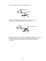
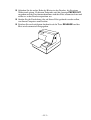
❏ Push the right edge of the paper into the printer until it stops. At that time,
the PAPER OUT indicator will go out, and the printer mechanism will
automatically align the paper for printing from the top.
❏ Send data from your host computer to be printed on the paper.
❏ After printing, press the RELEASE button to automatically release the
paper.
– 18 –
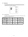
4.9 Control Panel Operations
The control panel gives you some push-button control over the slip printer
operation. It also includes indicator lights, which tell you the current status of
the printer at a glance.
FORWARD
POWER
RELEASE
PAPER
OUT
REVERSE
RELEASE
4.9.1
Indicator lights
The following table describes the meaning of indicator lights when it is on, off,
or flashing.
Indicator Light
Off
On
Flashing
POWER
Power off
Power on
Dot Alignment Adjust
Mode
PAPER OUT
Paper inserted
No paper
Insert paper prompt
RELEASE
Slip paper engaged
Slip paper released
Mechanical error
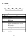
4.9.2
Buttons
The following table describes the function of the three control buttons of the
control panel.
Button
Description
FORWARD
Feeds the slip paper forward, toward the back of the printer. One press
feeds one line, holding down performs continuous feed.
REVERSE
Feeds the slip paper back, toward the front of the printer. One press
feeds one line, holding down performs continuous feed.
RELEASE
Activates the printer's paper release (the paper is not held in place by
the paper feed roller).
Clears recoverable errors.
– 19 –
4.9.3
Producing a test print
The following procedure can be used at any time to test the printer.
❏ Turn on the printer and insert a piece of paper (page 11, 16).
❏ Turn off printer power.
❏ While holding down RELEASE, turn printer back on. Keep RELEASE
depressed for a few moments until the printer beeps and the printer test
print starts.
The printer test will continue until it reaches the end of the paper.
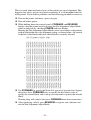
4.9.4
Adjusting the dot alignment
You may never have to use the procedure described in this section, but after you
have been using your printer for some time you may find that the dots of some
graphics do not align correctly. For example, what should look like:
may come out looking like one of the following:
or like this
– 20 –
This is caused when mechanical parts of the printer get out of alignment. This
happens only rarely and you may never experience it at all throughout the life
of the printer. If you do have problems, use the following procedure to correct it.
❏ Turn on the printer and insert a piece of paper.
❏ Turn off printer power.
❏ While holding down the control panel’s FORWARD and REVERSE
buttons, turn the printer back on to enter the Dot Alignment Adjust Mode,
which is indicator by a flashing POWER indicator flashes.
Entering the Dot Alignment Adjust Mode causes seven blocks to be printed,
each of which indicates a dot alignment setting, as shown below. An asterisk
to the left of the blocks indicates which block is currently selected.
❏ Use FORWARD to specify the block that appears to have the best aligned
characters. Press FORWARD once to specify the first block, twice to
specify the second block, and so on up to seven times to specify the seventh
block.
Warning beep will sound if you press FORWARD more than seven times.
❏ After specifying a block, press REVERSE to register your selection and
exit the Dot Alignment Adjust Mode.
– 21 –
The dots alignment adjustment setting you selected is stored in printer memory
and a pattern is printed using the selected setting followed by the message
“Adjust Complete!” The printer ejects the paper after printing is complete.
Note:
You setting is not registered if you turn off printer power before pressing
REVERSE to exit the Dot Alignment Adjust Mode.
If a paper feed error occurs during this mode, the printer ejects the paper and
this mode is cancelled.
4.9.5
Hexadecimal dump
This procedure prints in hexadecimal format all codes (character codes and
control codes) that are sent to the printer by the computer. The printer does not
execute any control codes (such as 0A - linefeed), it just prints them out. The
hexadecimal dump is useful when you are writing programs for printer control.
❏ Turn on the printer and insert a piece of paper.
❏ Turn off printer power.
❏ While holding down the control panel’s FORWARD buttons, turn the
printer back on to enter the Hex Dump Mode.
❏ To exit the Hex Dump Mode, turn the printer off.
Note:
The printer will not responde to any commands you send it while it is in the
Hex Dump Mode.
– 22 –
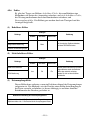
4.9.6
Errors
There are three types of errors: recoverable errors that require some action by
you before they clear, non-recoverable errors that require servicing by an
authorized service provider, and a data receive error. Errors are indicated by and
audible buzzer and the indicators.
(1) Recoverable Errors
Indicators
Error Type
Recovery
POWER
RELEASE
PAPER OUT
Paper jam
Carriage motor lockup
Correct the cause of the problem and
then press RELEASE.
Flashing
Abnormal home position signal
Abnormal timing signal
(2) Non-recoverable Errors
Indicators
Error Type
Recovery
POWER
RELEASE
PAPER OUT
RAM read/write
Off
On
CPU lockup
On
Turn off the printer, then after waiting a
few minutes, turn the printer back on. If
the printer does not recover, contact
your nearest service provider.
(3) Data Receive Error
This type of error is caused whenever a problem is encountered during data
receipt. The method used by the printer to recover from a data receive error
depends on the current command mode.
Data Receive Error Recover Procedure
Memory switch 4-0=0 : The printer prints a question mark.
Memory switch 4-0=1 : The printer discards the received data.
– 23 –
4.10 Paper Sensors
The following paper sensors are available.
❏ TOF Sensor
This top-of-form sensor detects the leading edge of the paper.
When enabled, the TOF sensor detects when there is no paper present and
stops printing.
❏ BOF Sensor
This bottom-of-form sensor detects the trailing edge of the paper. When
enabled, the BOF sensor detects when there is no paper present and printing
is interrupted.
When the TOF or BOF sensor detects that no paper is present, the printer stops
its motor after printing of 0 to a maximum of two more lines.
The BOF sensor detects a paper out condition whenever the distance between
print head pin #9 and the trailing edge of the paper becomes 38.1 mm or less.
The print stop operation is not entered until the distance between print head pin
#9 and the trailing edge of the paper becomes 27.3 mm or less.
When the auto clamp is enabled with Memory Switch 5-1, the auto clamp
operation is performed about 1.0 second (Initial value is approximately
1 second) after the presence of paper is detected both by the TOF and BOF
sensors, following a paper out condition. The auto clamp function is not affected
by whether the TOF or BOF sensor is enabled or disabled.
The top of form positioning function is enabled with Memory Switch 5-0. Even
if the auto clamp function is disabled, auto top of form positioning is performed
if the paper is clamped when printing starts.
The PAPER OUT lamp flashes to request insertion of paper when the sensors
detect there is no paper (when a sensor enabled by command detects no paper)
after data is received by the printer. At that time, the user inserts paper, and
printing begins after the sensor detects that paper is present.
– 24 –
5. Making DIP Switch Settings
The printer’s DIP switches let you specify communications parameters, receive
buffer size, and emulation. This “5. Making DIP Switch Settings” explains the
settings you can make and tells you how to actually change DIP switch settings.
5.1 Accessing the DIP switches
The DIP switches are located inside the printer, underneath the document table.
Use the following procedure to remove the document table so you can operate
the DIP switches.
❏ Make sure that the printer is turned off and unplugged from its wall outlet.
❏ Remove the printer cover.
❏ While using a screwdriver or other similar instrument to press down at the
location marked (a) in the illustration below, carefully slide the document
table in the direction indicated by the arrow until it is out of the way.
a
– 25 –
OFF
ON
It is not necessary to remove the document table completely, just move it
enough so you can get at the DIP switches inside.
ON
1
2
3
4
5
6
7
8
9
10
OFF
Note:
If the document table seems to be getting caught on the rollers, it means that
you are not pressing down at point (a) enough. Pressing at point (a) should
separate the rollers to the document table can slide freely.
❏ After the document table is opened sufficiently, use a thin flat-blade
screwdriver or some other similar object to change DIP switch settings.
Note:
See the following section for details on available DIP switch settings.
❏ After making the settings you want, slide the document table back into
place while pressing down at point (a). Make sure that the document table
is correctly seated in place before releasing point (a).
❏ Replace the printer cover.
– 26 –
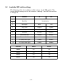
5.2 Available DIP switch settings
The following table shows all the possible settings for the DIP switch. The
factory default settings are ON for switches 1 through 7 and OFF for switches
8 through 10.
Switch
Parameter
ON
OFF
1
Baud Rate
See table below
2
3
Data Length
8 bits
7 bits
4
Parity Check
Disabled
Enabled
5
Parity
Odd
Even
6
Handshake
DTR/DSR
XON/XOFF
7
Receive Buffer Size
2K bytes
35 bytes
8
Character Code Set
Japanese (Katakana)
International (PC437)
9
Pin 6 (DSR) Reset Signal
Enabled
Disabled
10
Pin 25 (INIT) Reset Signal
Enabled
Disabled
Baud Rate
Switch 1
Switch 2
1200BPS
OFF
OFF
2400BPS
ON
OFF
4800BPS
OFF
ON
9600BPS
ON
ON
– 27 –
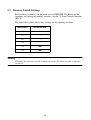
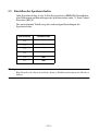
5.3 Memory Switch Settings
Each memory switch is a 16-bit word store in EEPROM. For details on the
functions and settings of memory switches, see the “9. Print Control Functions
(ESC#)”.
The table below shows the factory settings for the memory switches.
Memory Switch
Hexadecimal Code
#0
–
#1
–
#2
–
#3
–
#4
0000
#5
0000
Warning!
Changing the memory switch settings can cause the printer to fail to operate
correctly.
– 28 –
6. Interface
This appendix provides detailed specifications for the printer’s standard serial
interface.
13
1
25
14
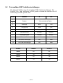
6.1 Pins and Signal Names
Pin
No.
Signal
Direction
Name
1
FG
—
2
TXD
OUT
3
RXD
IN
4
RTS
OUT
5
N.C.
6
DSR
Function
Frame ground
Transmission data
Receive data
Same as DTR signal
Not connected
IN
• DIP Switch 9 = OFF
In DTR/DSR communication mode when Memory Switch4-5 = 0, indicates whether data
receive from host is enabled or disabled.
Space: Receive enabled
Mark: Receive disabled
This signal is not checked in the X-ON/X-OFF communication mode.
• DIP Switch 9 = ON
This signal used for external reset. Printer is reset whenever signal is in mark state with
pulse width of 1mS or more.
7
SG
Signal ground
8 -19
N.C.
Not connected
– 29 –
Pin
No.
Signal
Direction
Name
20
DTR
21 - 24
N.C.
25
INIT
OUT
Function
Indicates whether data receive from host is enabled or disabled.
DTR/DSR Communication Mode
Space when receive is enabled.
X-On/X-Off Communication Mode
Always space, except during following conditions:
• Period between reset and communication enabled
• During self-test printing and dot alignment adjustment
Not connected
IN
• DIP Switch 10 = OFF
This signal not used.
• DIP Switch 10 = ON
This signal becomes reset signal. Printer is reset whenever signal is in mark state with
pulse width of 1mS or more.
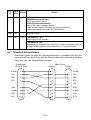
6.2 Interface Connections
Refer to the interface specifications of the host for details on connecting to its
interface connector. The following illustration shows a typical connection
configuration.
Printer side
(D-sub 25 pin)
IBM PC side
25 pin
9 pin
F-GND
1
1
TXD
2
2
3
TXD
RXD
3
3
2
RXD
RTS
4
4
7
RTS
5
8
CTS
F-GND
DSR
6
6
6
DSR
S-GND
7
7
5
S-GND
DTR
20
8
1
DCD
INIT
25
20
4
DTR
– 30 –
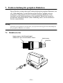
7. Peripheral Unit Driver Circuit
This printer is equipped with a circuit for driving peripheral units, such as cash
drawers. A 6-pin modular connector for connection of the peripheral unit is
located on the back of the printer. To connect to the drive circuit, connect the
peripheral unit to the modular connector using a cable supplied by you like that
one shown in the figure below.
Important!
Never connect any other type of plug to the peripheral unit connector.
7.1 Modular plug
Modular plug: MOLEX 90075-0007,
AMP641337, or JAPAN BURNDY B-66-4
Shield
1
6
Wire lead
– 31 –
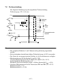
7.2 Drive circuit
The recommended drive unit is shown below.
Drive output: 24V, 1.0A max.
1
F.G
With shield
2
TR1
D1
Peripheral
unit 1
3
7824
+24V
M-GND
L1
4
D2
TR2
L2
R3
4.7kΩ
1/4W
5
M-GND
Peripheral
unit 2
+5V
R1
Compulsion
switch
6
TR3
R2
Frame
ground
Printer side
User side
Notes
•
•
•
•
•
Peripheral Units 1 and 2 cannot be driven simultaneously.
For continuous driving, do not use drive duty greater than 20%.
Compulsion switch status is available as status data.
Minimum resistance for coils L1 and L2 is 24Ω.
Absolute maximum ratings for diodes D1 and D2 (Ta = 25°C) are:
Average Rectified Current Io = 1A
Maximum forward surge current (60Hz, 1-cycle sine wave) IFSM = 40A
• Absolute maximum rating for transistors TR1 and TR2 (Ta = 25°C) are:
Collector current Ic = 2A
Collector loss Pc = 1.2W
– 32 –
8. Maintenance and Service
For the information on maintenance and service, please contact our dealer.
– 33 –
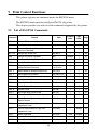
9. Print Control Functions
This printer supports one command mode: the ESC/POS mode.
The ESC/POS mode emulates the Epson TM-295 slip printer.
This chapter provides you with all of the commands supported by this printer.
9.1 List of ESC/POS Commands
Command
Function
Code
Standard
Mode
Page
Mode
Page
HT
Horizontal Tab
09H
37
LF
Line Feed
0AH
37
FF
Prints and Ejects Single Sheet, and Prints and
Returns in Paper Mode
0CH
38
DLE EOT
Sends Status at Real Time
10H 04H n
39
CAN
Cancels Print Data in Page Mode
18H
Disabled
42
ESC SP
Sets Space Size to Right of Characters
1BH 20H n
42
ESC !
Selects Print Mode in Batch
1BH 21H n
43
ESC #
Sets Memory Switch
(Unique Extension Command)
1BH 23H N
n1 n2 n3 n4
44
ESC %
Selects/Deselects Download Character Set
1BH 25H n
46
ESC &
Defines Download Characters
1BH 26H y c1 c2
47
ESC
Selects Bit Image Mode
1BH 2AH m
49
ESC 2
Sets 1/6-inch Line Feed
1BH 32H
51
ESC 3
Sets n/60-inch Line Feed (Approximate Value)
1BH 33H n
51
ESC =
Selects Peripheral Device
1BH 3DH n
52
ESC @
Initializes Printer
1BH 40H
53
ESC C
Sets Single Sheet Ejection Length
1BH 43H
53
ESC D
Sets Horizontal Tab Position
1BH 44H
54
ESC F
Selects/Deselects Ejection of Single Sheet in
Reverse Direction
1BH 46H n
55
ESC J
Print and n/60-inch Paper Feed
(Approximate Value)
1BH 4AH n
55
ESC K
Print and n/60-inch Reverse Paper Feed
(Approximate Value)
1BH 4BH n
Disabled
56
ESC L
Selects Page Mode
1BH 4CH n
(Line)
Disabled
57
ESC R
Selects International Characters
1BH 52H n
58
ESC T
Selects Character Print Direction in Page Mode
1BH 54H n
(Set)
59
– 34 –
Command
Function
Code
Standard
Mode
Page
Mode
Page
(Set)
60
ESC W
Sets Print Area in Page Mode
1BH 57H
ESC c4
Selects No-paper Sensor Valid for Print Stop
1BH 63H 34H n
61
ESC c5
Enables/Disables Panel Switch
1BH 63H 35H n
62
ESC d
Print and N-line Paper Feed
1BH 64H n
62
ESC e
Print and N-line Reverse Paper Feed
1BH 65H n
Disabled
63
ESC f
Sets Single Sheet Waiting Time
1BH 66H t1 t2
63
ESC p
Generates Specified Pulses
1BH 70H m t1 t2
64
ESC q
Release
1BH 71H
Disabled
65
ESC t
Selects Character Code Table
1BH 74H n
66
ESC u
Sends Peripheral Device Status
1BH 75H n
67
ESC v
Sends Paper Sensor Status
1BH 76H
68
ESC {
Selects/Deselects Inverted Print
1BH 7BH n
(Line)
(Set)
69
GS I
Sends Printer ID
1DH 49H n
70
GS a
Enables/Disables Automatic Status Sending
1DH 61H n
71
GS r
Sends Status
1DH 72H n
74
: Enabled
(Line) : Enabled only at the head of the line
(Set) : Only setting is enabled
: Only part of setting is enabled
: Ignores partially Disabled: An argument is processed as next data
– 35 –
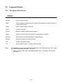
9.2 Command Details
9.2.1
Description of Each Items
XXXX
[Function]
Shows a command function.
[Code]
Shows a sequence of code consisting the command; ASCII represents the ASCII code and [ ]k
a repeat count of k-times.
[Range]
Shows a settable range of an argument.
[Outline]
Outlines the command.
[Caution]
Describes a caution for the command as required.
[Default]
Describes an initial value for the command, if accompanied by an argument.
[See Also]
Describes other associated commands in using the command.
[Example]
Describes an example of using the command.
< >H:
Denotes a hexadecimal number.
< >B:
Denotes a binary number. < >: Denotes a decimal number.
Notes
Of "Enabled only at the head of the line" in Section 9.1, the "head of the line" refers to the
case when the following condition is satisfied.
(1) There is no print data (space and skipping portion by HT included) in the current
print buffer.
– 36 –
9.2.2
Command Details
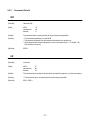
HT
[Function]
Horizontal Tab
[Code]
ASCII
Hexadecimal
Decimal
[Outline]
This command shifts a printing position to the next horizontal tab position.
[Caution]
• The horizontal tab position is set by ESC D.
• The command is ignored if the next horizontal tab position has not been set.
• Initial setting of the horizontal tab position is every 8 characters of the 5 × 7 font(9th, 17th,
25th character, and so on)
[See Also]
ESC D
HT
09
9
LF
[Function]
Line Feed
[Code]
ASCII
Hexadecimal
Decimal
[Outline]
This command prints the data in the print buffer and feeds the paper by a set line feed amount.
[Caution]
• The head of the line is assumed to be the next printing start position.
[See Also]
ESC 2, ESC 3
LF
0A
10
– 37 –
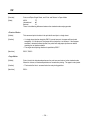
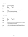
FF
[Function]
Prints and Ejects Single Sheet, and Prints and Returns in Paper Mode
[Code]
ASCII
FF
Hexadecimal
0C
Decimal
12
There is the following difference between the standard mode and page mode:
<Standard Mode>
[Outline]
This command prints the data in the print buffer and ejects a single sheet.
[Caution]
• If a single sheet ejection length by ESC C has not been set, the paper will be ejected
completely. If it has been set, the paper will be ejected by a set amount. If the no-paper
condition is detected halfway ejection, the printer will stop paper ejection even before
reaching the set ejection amount.
• The single sheet ejecting direction is specified by ESC F.
[See Also]
ESC F, ESC C
<Page Mode>
[Outline]
Prints in batch the data developed across the print area and returns to the standard mode.
When this is done, all the developed data are erased after printing. The paper is not ejected.
[Caution]
• The head of the line is assumed to be the next printing position.
[See Also]
ESC L
– 38 –
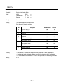
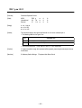
DLE EOT n
[Function]
Sends Status at Real Time
[Code]
ASCII
Hexadecimal
Decimal
[Range]
1 n 3, n = 5
[Outline]
This command sends the n-specified status at real time.
DLE EOT n
10
04
n
16
4
n
n
[Caution]
Description
1
Sends the printer status.
2
Sends the off-line factor status.
3
Sends the error factor status.
5
Sends the slip status.
•
•
•
•
For the status sent, see the tables on the following pages.
This command runs processing upon its reception.
When sending the status, only one byte is sent without confirming the DSR signal status.
The command is executed in the off-line state, reception buffer full state, and error state as
well.
• The user should note that the operation of this command is also executed when a data
sequence of <10>H<04>H<n> (1 n 3, n = 5) is received, other than this command.
<Example>
d1 = <10>H, d2 = <04>H, d3 = <1> in ESC * m nL nH [d]nL + 256 × nH
• This command must not be used by interrupting the code sequence of other command
consisting of 2 bytes or more.
<Example>
If DLE EOT 3 is sent after sending up to ESC 3, attempting to send ESC 3 n from the host, it
will be processed as ESC 3 n = <10>H. Therefore, the use should take heed of this.
• If ASB has been enabled by GS a, it is necessary to distinguish the status by this command
from that of ASB. See “6. Interface” for how to distinguish them
• If n is beyond the range, this command will be ignored.
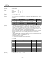
– 39 –
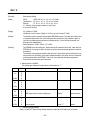
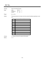
n = 1: Printer status
Bit
Description
Hexadecimal
Decimal
0
Unused
00
0
1
Unused
02
2
2
Status of the drawer kick connector No. 3 pin = L
00
0
Status of the drawer kick connector No. 3 pin = H
04
4
On-line status
00
0
Off-line status
08
8
4
Unused
10
16
5
Undefined
–
–
6
Undefined
–
–
7
Unused
00
0
Hexadecimal
Decimal
3
n = 2: Off-line factor status
Bit
Description
0
Unused
00
0
1
Unused
02
2
2
Undefined
–
–
3
Not feeding the paper by the Paper Feed switch
00
0
Feeding the paper by the Paper Feed switch
08
8
4
Unused
10
16
5
No print stop because of no paper.
00
0
Print stop because of no paper.
20
32
No error
00
0
Error
40
64
Unused
00
0
6
7
Bit 5 : If there is no paper when the TOF or BOF sensor enables no-paper print stop by ESC c 4, the printer
will stop printing, resulting in 32 (print stopping).
– 40 –
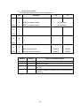
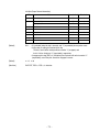
n = 3: Error factor status
Bit
Description
Hexadecimal
Decimal
0
Unused
00
0
1
Unused
02
2
2
Undefined
–
–
3
Undefined
–
–
4
Unused
10
16
5
No irrecoverable error
00
0
Irrecoverable error
20
32
6
Undefined
–
–
7
Unused
00
0
Hexadecimal
Decimal
n = 5: Slip status
Bit
Description
0
Unused
00
0
1
Unused
02
2
2
The slip has been selected
00
0
3
Slip insertion non-waiting status
00
0
Slip insertion waiting status
08
8
4
Unused
10
16
5
Paper set in the BOF sensor
00
0
No paper set in the BOF sensor
20
32
Paper set in the TOF sensor
00
0
No paper set in the TOF sensor
40
64
Unused
00
0
6
7
Bit 3 : Detects a slip of paper and results in 0 immediately before starting the operation (not waiting for
insertion)
Bits 5, 6 : Send the current status of the TOF and BOF sensors.
[See Also]
ESC u, ESC v, GS a, 6. Interface
– 41 –
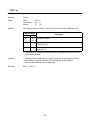
CAN
[Function]
Cancels Print Data in Page Mode
[Code]
ASCII
Hexadecimal
Decimal
[Outline]
This command erases all the print data in the current print area in the page mode.
[Caution]
• This command is valid only in the page mode.
• Even the print data in the previously set print area is erased, if it is extended over the
currently set print area.
[See Also]
ESC W
CAN
18
24
ESC SP n
[Function]
Sets Space Size to Right of Characters
[Code]
ASCII
Hexadecimal
Decimal
[Range]
0 n 32
[Outline]
This command sets the right space size of the characters.
[Caution]
•
•
•
•
[Default]
n=0
ESC SP
1B 20
27
32
n
n
n
In the double width mode, the right space size is doubled.
The space size is set in increments of half dot.
In the page mode, the space size may be shifted a half dot from a set value.
There are two set values for the standard and page modes, respectively.
– 42 –
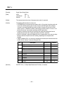
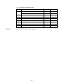
ESC ! n
[Function]
Selects Print Mode in Batch
[Code]
ASCII
Hexadecimal
Decimal
[Range]
0 n 32
[Outline]
This command specifies the print mode.
Each bit has the following meaning.
ESC !
1B 21
27
33
Bit
n
n
n
Hexadecimal
Decimal
Character font 5 × 7
00
0
Character font 7 × 7
01
1
1
Undefined
–
–
2
Undefined
–
–
3
Undefined
–
–
4
Deselects double height
00
0
Selects double height
10
16
Deselects double width
00
0
Selects double width
20
32
6
Undefined
–
–
7
Deselects underline
00
0
Selects underline
80
128
0
5
Description
[Caution]
• The underline is drawn across the print character width, not the blank skipped by HT.
• If both double height and double width are specified, the characters will be quadrupled.
• For selection of the underline and 7 × 7 font in the page mode, only their setting is enabled.
[Default]
n=0
– 43 –
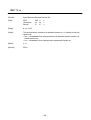
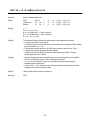
ESC #
[Function]
Sets Memory Switch
[Code]
ASCII
<ESC>"#N, n1 n2 n3 n4" <LF> <NUL>
Hexadecimal 1B 23 N 2C n1 n2 n3 n4 0A 00
Decimal
27 35 N 44 n1 n2 n3 n4 10 0
N : Memory switch segment number (4 and 5 only)
n1 n2 n3 n4: Set data
[Range]
N="4"(34h) or "5"(35h)
"0"(30h)n1,n2,n3,n4"9"(39h) or "A"(41h)n1,n2,n3,n4"F"(46h)
[Outline]
The memory switch is stored in the nonvolatile EEPROM memory. To change this setting, send
a command from the host side. After setting with the command, turn on the power again, or
reset with the following reset command, to enable setting. (If reset with the command, selfprinting will be implemented.)
Reset command: <ESC> <CAN> <LF> <NUL>
[Caution]
The EEROM has a data-writing life. Do not execute this command every time. Note that if the
EEROM’s life is running out due to frequent use of this command, printer operation cannot be
guaranteed.
The memory switch segment numbers other than 3 to 5 do not have relevant setting items, but
they actually exist. Therefore, use of other numbers besides 3 to 5 will be valid as a command
and change the data in the EEROM. If this is the case, operation will not be guaranteed.
Exercise full care when using this command.
1) Memory Switch 4 (MSW4)
The setting upon shipment from the factory is indicated with “ * ”.
Bit
n1
(LSB)
n2
(LSB)
n3
(LSB)
n4
(LSB)
F
E
D
C
B
A
9
8
7
6
5
4
3
2
1
0
Description
0
1
DSR signal check at status sending time
Checks *
Does not check
Data reception
Prints "?" *
Ignores
( : Denotes setting enabled)
(Note) X-ON/X-OFF output timing: Setting whether to output the X-ON code every 3 seconds
– 44 –
2)
Memory Switch 5 (MSW5)
The setting upon shipment from the factory is indicated with “ * ”.
Bit
Description
0
1
F
n1
(LSB)
E
D
<ESC> "q" command function
See Table below
C
<ESC> "q" command function
See Table below
B
n2
A
9
(LSB)
8
7
n3
6
5
(LSB)
4
3
n4
(LSB)
2
1
Automatic clamp function
Enabled *
Disabled
0
Automatic head search function
Enabled *
Disabled
MSW5-D
MSW5-C
<ESC> “q” Command Function
0*
0*
Implements releasing *
1
0
Implements releasing
0
1
Implements releasing after discharging all in the forward direction
(far side).
1
1
Implements releasing after discharging all in the reverse direction
(near side).
– 45 –
ESC % n
[Function]
Selects/Deselects Download Character Set
[Code]
ASCII
Hexadecimal
Decimal
[Range]
0 n 255
[Outline]
This command selects or deselects the download character set. n is valid only for the least
significant bit.
• At n = <0>B, the command deselects the download character set(selects an
internal character set).
• At n = <1>B, the command selects the download character set.
[Default]
n=0
[See Also]
ESC &
ESC %
1B 25
27
37
n
n
n
– 46 –
ESC & y c1 c2 [x[d]yxx]c2-c1+1
[Function]
Defines Download Characters
[Code]
ASCII
Hexadecimal
Decimal
[Range]
y=1
32 c1 c2 126
0 x 6 (When the 5 × 7 font is selected)
0 x 10 (When the 7 × 7 font is selected)
0 d1 ... d y × x 255
[Outline]
This command defines the font of the alphanumeric or Kana download characters.
• y denotes the number of vertical bytes.
• c1 denotes the start character code and c2, end character code, respectively. When defining
only one character, set c1 = c2.
• The definable character code is the 95 ASCII code characters from <20>H to <7E>H.
• x denotes the number of horizontal dots to be defined.
• d denotes the data to be defined; a horizontal x dots pattern from the left. The right
remaining pattern results in spaces.
[Caution]
• Once the download characters are defined, they will remain valid until they are redefined,
ESC @ is executed, the printer is reset, or the power is turned off.
• If y, c1, c2, or x is beyond the range, this command will be ignored, processing the
subsequent data as normal one.
• In case of the 7 × 7 font, define the data so that the horizontally adjacent dots will not be
contained, because they cannot be printed.
[Default]
Identical pattern with the internal character set
[See Also]
ESC %
ESC &
1B 26
27
38
y
y
y
– 47 –
c1
c1
c1
c2
c2
c2
[x [d] y × x ] c2-c1+1
[x [d] y × x ] c2-c1+1
[x [d] y × x ] c2-c1+1
[Example]
• When selecting the 5 × 7 font
p1 p2 p3 p4 p5 p6
MSB
LSB
When defining the pattern above to the code 20H
ESC &
y
c1
c2
x
Code (hex.)
1B
26
01
20
20
05
p1
p2
p3
p4
p5
3E
48
88
48
3E
• When selecting the 7 × 7 font
p1 p2 p3 p4 p5 p6 p7 p8 p9 p10
MSB
LSB
When defining the pattern above to the code 20H
ESC &
y
c1
c2
x
Code (hex.)
1B
26
01
20
20
07
p1
p2
p3
p4
p5
p6
p7
1E
20
48
80
48
20
1E
– 48 –
ESC * m nL nH [d]k
[Function]
Selects Bit Image Mode
[Code]
ASCII
Hexadecimal
Decimal
[Range]
m = 0, 1
0 nL 255
0 nH 3
0 d 255
k = nL nH × 256
[Outline]
• This command specifies the bit image of the m-mode as to the number of dots specified with
nL and nH.
• nL and nH denote the number of horizontal dots of the bit image to be printed, resulting in [nL
+ nH × 256] dots.
• If the bit image data is input beyond the dot position printable in one line, the surplus data will
be discarded.
• d denotes the bit image data. Set "1" in the corresponding bit when printing, and "0" when
not printing.
• The following table lists the bit image mode selected with m.
ESC *
1B 2A
27 42
m
m
m
nL
nL
nL
nH
nH
nH
[d] k
[d] k
[d] k
Vertical Direction
Horizontal Direction (*1)
Dots
Max. Dots
m
Mode
0
8-dots single density
8
210
1
8-dots double density
8
420
*1: The total number of horizontal dots in the page mode differs depending on the printing area
secured with ESC W and printing direction specified with ESC T.
[Caution]
• If a value of m or nH goes beyond the range, this command will be ignored, processing the
subsequent data as normal one.
• Normal data processing is restored after printing the bit image.
• The following page shows the relations between the bit image data and the dots printed.
• The double density bit image is invalidated in the page mode.
– 49 –
• The following shows the relations between the bit image data and the dots printed.
7 6 5 4 3 2 1 0
Bit Image Data
High
Low
Print Data
– 50 –
ESC 2
[Function]
Sets 1/6-inch Line Feed
[Code]
ASCII
Hexadecimal
Decimal
[Outline]
This command sets a line feed amount per line to 1/6 inch.
[Caution]
There are two kinds of line feed amounts for the standard mode and page mode.
• For the standard mode: Set to 1/6 inch.
• For the page mode: Set to 10 dots (10/72 inch)
[See Also]
ESC 3
ESC 2
1B 32
27
50
ESC 3 n
[Function]
Sets Line Feed Amount
[Code]
ASCII
Hexadecimal
Decimal
[Range]
0 n 255
[Outline]
This command sets a line feed amount per line to n/60 inch.
[Caution]
There are two kinds of set values for the standard mode and page mode. Since the printer has
the minimum paper feed pitch of 1/144 inch, the line feed amount of n/60 inch is treated as
follows:
• For the standard mode: Set an approximate value of INT((6n+5)+0.5)/72 inch.
• For the page mode: Set n/72 inch(n coordinate).
[Default]
n = 10 (1/6 inch for the standard mode and 10 dots (10/72 inch for the page mode))
[See Also]
ESC 2
ESC 3
1B 33
27
51
n
n
n
– 51 –
ESC = n
[Function]
Selects Peripheral Device
[Code]
ASCII
Hexadecimal
Decimal
[Range]
0n3
[Outline]
This command selects a peripheral device which validates the subsequent data, depending on
a value of n.
• Each bit has the following different meanings.
• If Printer Disabled has been selected, the printer will discard all the received data until Printer
Enabled is selected with this command.
ESC =
1B 3D
27
61
Bit
n
n
n
Hexadecimal
Decimal
Printer Disabled
00
0
Printer Enabled
01
1
1
Undefined
–
–
2
Undefined
–
–
3
Undefined
–
–
4
Undefined
–
–
5
Undefined
–
–
6
Undefined
–
–
7
Undefined
–
–
0
Peripheral Device
[Caution]
• Even if Printer Disabled has been selected, the printer may be made off-line by operating it.
[Default]
n=1
– 52 –
ESC @
Fnction]
Initializes Printer
[Code]
ASCII
Hexadecimal
Decimal
[Outline]
This command clears the data in the print buffer to initialize various settings.
[Caution]
• The setting of the DIP switch is not re-read.
• The data in the reception buffer is not cleared.
ESC @
1B 40
27
64
ESC C n
[Function]
Sets Single Sheet Ejection Length
[Code]
ASCII
Hexadecimal
Decimal
[Range]
0 n 127
[Outline]
This command sets a single sheet ejection length to n lines.
• If n = 0, the ejection length will not be set
[Caution]
• Even if the line feed amount is changed after setting the ejection length, the latter will not
change
• The ejection length set here is meaningful only when FF is executed
[Default]
n=0
[See Also]
FF
ESC C
1B 43
27
67
n
– 53 –
ESC D [n]k NUL
[Function]
Sets Horizontal Tab Position
[Code]
ASCII
Hexadecimal
Decimal
[Range]
1 n 255
0 k 32
[Outline]
This command sets a horizontal tab position.
• n denotes the number of columns from the head of the line to the horizontal tab setting
position. n is equal to the setting column position - 1, and if the horizontal tab is to be set in
the 9th column, for example, set n = 8.
• k denotes the number of horizontal tab positions to be set.
• The tab position is set to the position at a distance of the character width × n from the head of
the line. This character width includes the right space size of the character, and if double
width is selected, the character width will be doubled. A horizontal magnification selection is
followed even in the page mode.
• The data, <n>k, which denotes a setting position is input in the ascending order and ends
with <00>H.
• ESC D NUL clears all the set tab positions. After clearing, HT is ignored.
[Caution]
• If the data <n>k is equal to or smaller than the preceding data <n>k-1, it is assumed that
horizontal tab setting has been finished. If this is the case, the subsequent data will be
processed as normal one.
• Up to 32 tab positions can be set. The data exceeding this limit is processed as normal data.
• If HT is executed, a move to the tab position beyond the print area will be made to the
position of the print area + 1 dot.
• Even if the character width is changed after setting the horizontal tab position, the latter will
not change.
• There are two kinds of right space sizes of the characters; for the standard mode and page
mode. To set the horizontal tab position in the respective modes, set the right space size of
the characters in the very mode you are in.
[Default]
Every 8 characters of the 5 × 7 font (9th, 17th, 25th character, and so on)
[See Also]
HT
ESC D
1B 44
27
68
[n] k NUL
[n] k 00
[n] k 0
– 54 –
ESC F n
[Function]
Selects/Deselects Ejection of Single Sheet in Reverse Direction
[Code]
ASCII
Hexadecimal
Decimal
[Range]
0 n 255
[Outline]
This command selects or deselects single sheet ejection in the reverse direction with FF.
• n is valid only for the least significant bit.
At n = <1>B, the command selects reverse directional ejection.
At n = <0>B, the command deselects reverse directional ejection(selects
forward directional ejection).
[Default]
n=0
[See Also]
FF
ESC F
1B 46
27
70
n
n
n
ESC J n
[Function]
Print and Paper Feed
[Code]
ASCII
Hexadecimal
Decimal
[Range]
0 n 255
[Outline]
This command prints the data in the print buffer and feeds the paper by n/60 inch. Since the
printer has the minimum paper feed pitch of 1/144 inch, a paper feed amount of n/60 inch is
treated as follows:
• For the standard mode: The paper is fed by an approximate value of INT((6n+5)+0.5)/72
inch.
• For the page mode: The paper is fed by n/72 inch(n coordinate).
[Caution]
The head of the line is assumed to be the next printing start position.
ESC J
1B 4A
27
74
n
n
n
– 55 –
ESC K n
[Function]
Print and Reverse Paper Feed
[Code]
ASCII
Hexadecimal
Decimal
[Range]
0 n 255
[Outline]
This command prints the data in the print buffer and feeds the paper by n/60 inch in the reverse
direction. Since the printer has the minimum paper feed pitch of 1/144 inch, n/60-inch reverse
directional paper feed is treated as follows:
• For the standard mode: The paper is fed by an approximate value of INT((6n+5)+0.5)/72
inch.
[Caution]
• The command is valid only in the standard mode.
• The head of the line is assumed to be the next printing start position.
• A set amount does not remain.
ESC K
1B 4B
27
75
n
n
n
– 56 –
ESC L
[Function]
Selects Page Mode
[Code]
ASCII
Hexadecimal
Decimal
[Outline]
This command switches from the standard mode to the page mode.
• The page mode deploys the received data over the specified print area and prints it in batch
with the FF command. Consequently, normal print commands such as LF only deploy the
data in the printer’s memory, but not actually print it.
• The printer returns to the standard mode after printing the data in the specified print area with
FF.
[Caution]
• The command is valid only when it is input at the head of the line.
• In the page mode, half dots are not used, but only normal dots. Therefore, you should take
heed in setting in increments of half dot in the standard mode.
• Only the font consisting of normal dots is valid.
• The following commands have two kinds of set values for the standard mode and page
mode:
ESC SP Sets the right space size of the characters
ESC 2
Sets the 1/6-inch line feed amount
ESC 3
Sets the line feed amount
• The following commands are ignored in the page mode:
ESC K
Print and reverse directional paper feed
ESC e
Print and n-line reverse directional paper feed
ESC *
Specifies the double density bit image
ESC q
Release
• The following commands are valid only for their setting in the page mode:
ESC {
Selects/deselects the inverted characters
ESC !
Selects/deselects the 7 × 7 font and underline
• The command is valid only in the standard mode.
• ESC @ returns you to the standard mode without printing.
[Default]
The standard mode has been selected.
[See Also]
FF, 6. Interface
ESC L
1B 4C
27
76
– 57 –
ESC R n
[Function]
Selects International Characters
[Code]
ASCII
Hexadecimal
Decimal
[Range]
0 n 10
[Outline]
This command selects the character sets for the countries listed below, depending on a value
of n.
ESC R
1B 52
27
82
n
n
n
n
Character Set
0
U.S.A
1
France
2
Germany
3
England
4
Denmark I
5
Sweden
6
Italy
7
Spain
8
Japan
9
Norway
10
Denmark II
[Caution]
If n is beyond the range, this command will be ignored.
[Default]
n=0
– 58 –
ESC T n
[Function]
Selects Character Print Direction in Page Mode
[Code]
ASCII
Hexadecimal
Decimal
[Range]
0 n 3, 48 n 51
[Outline]
This command specifies the character printing direction and start point in the page mode. The
character printing direction is specified with n.
n = 0, 48 :→ (Start point at upper left: A)
n = 1, 49 :↑ (Start point at lower left: B)
n = 2, 50 :← (Start point at lower right: C)
n = 3, 51 :↓ (Start point at upper right: D)
n
n
n
C→→→→→→→
B→→→→→→→
D→→→→→→→
A→→→→→→→
Paper Feed Direction
ESC T
1B 54
27
84
[Caution]
• If the printing direction is specified or changed, the subsequent characters will have different
printing direction and start point(upper left, lower left, lower right, or upper right), depending
on a value of n.
• Only setting is valid in the standard mode.
• If n is beyond the range, this command will be ignored.
[Default]
n=0
– 59 –
ESC W xL xH yL yH dxL dxH dyL dyH
[Function]
Sets Print Area in Page Mode
[Code]
ASCII
Hexadecimal
Decimal
[Range]
0 xL 255, xH = 0, 0 yL 255, 0 yH 1, 0 dxL 255, dxH = 0
0 dyL 255, 0 dyH 1 (Except dxL = dxH = 0 or dyL = dyH = 0)
[Outline]
This command sets the position and size of the print area in the page mode.
• The upper left start point is represented by (x0, y0), y-directional(vertical) length by dy dots,
and x-directional(horizontal) length by dx dots.
x0 = [(xL + xH × 256)]
y0 = [(yL + yH × 256)]
dx = [(dxL + dxH × 256)]
dy = [(dyL + dyH × 256)]
ESC W
1B 57
27
87
xL
xL
xL
xH
xH
xH
yL
yL
yL
yH
yH
yH
dxL
dxL
dxL
dxH
dxH
dxH
dyL
dyL
dyL
dyH
dyH
dyH
(0, 0)
Printable Area on Paper
(x0, y0)
dx
dy
Print area
(x0+dx-1, y0+dy-1)
(209 dots, 479 dots)
[Caution]
• Setting beyond the printable area on the paper is automatically adjusted to the maximum
settable area, based on the effective values from xL to dyH (i.e., xL, xH, yL, yH, dxL, dxH,
dyL and dyH).
• The maximum x-directional dot in the printable area is 210.
• The maximum y-directional dot in the printable area is 480.
• When deploying the print data in the specified area, a print area length in the character
printing direction and vertical direction must be always 8 dots or more.
• Set the print area to the size fittable within the printing paper.
• If the start point (x0, y0) is beyond the printable area, this command will be ignored.
• Only setting is valid in the standard mode.
[Default]
xL = xH = yL = yH = 0, dxL = 210,
dxH = 0, dyL = 224, dyH = 1
[See Also]
CAN, ESC L, ESC T
– 60 –
ESC c 4 n
[Function]
Selects No-paper Sensor Valid for Print Stop
[Code]
ASCII
Hexadecimal
Decimal
[Range]
0 n 255
[Outline]
• This command selects in which status of the no-paper Sensor printing should be stopped.
Each bit has the following different meanings.
ESC c
1B 63
27
99
Bit
4
34
52
n
n
n
Sensor
Hexadecimal
Decimal
0
Undefined
–
–
1
Undefined
–
–
2
Undefined
–
–
3
Undefined
–
–
4
TOF sensor disabled
00
0
TOF sensor enabled
10
16
BOF sensor disabled
00
0
BOF sensor enabled
20
32
6
Undefined
–
–
7
Undefined
–
–
5
[Caution]
• It is possible to select multiple sensors as a printing stop condition, but if any one of them
detects the no-paper condition, the printer will stop printing.
• The printer stops printing after printing the on-going line and feeding the paper. If the panel
switch is disabled at this time, the printer will release the paper automatically and waits for
new paper to be set.
[Default]
n=0
[See Also]
ESC c 5
– 61 –
ESC c 5 n
[Function]
Enables/Disables Panel Switch
[Code]
ASCII
Hexadecimal
Decimal
[Range]
0 n 255
[Outline]
This command enables/disables the panel switch.
• n is valid only for the least significant bit.
At n = <0>B, the command enables the panel switch.
At n = <1>B, the command disables the panel switch.
[Caution]
• If the panel switch is disabled with this command, all the panel switches will be disabled.
[Default]
n=0
ESC c
1B 63
27
99
5
35
53
n
n
n
ESC d n
[Function]
Print and N-line Paper Feed
[Code]
ASCII
Hexadecimal
Decimal
[Range]
0 n 255
[Outline]
This command prints the data in the print buffer and feeds the paper by n-lines.
[Caution]
• The head of the line is assumed to be the next printing start position.
• The line feed amount set with ESC 2 or ESC 3 does not change.
[See Also]
ESC 2, ESC 3
ESC d
1B 64
27
100
n
n
n
– 62 –
ESC e n
[Function]
Print and N-line Reverse Paper Feed
[Code]
ASCII
Hexadecimal
Decimal
[Range]
0 n 255
[Outline]
This command prints the data in the print buffer and feeds the paper by n-lines in the reverse
direction.
[Caution]
• This command is valid only in the standard mode.
• The head of the line is assumed to be the next printing start position.
• The set amount does not remain.
ESC e
1B 65
27
101
n
n
n
ESC f t1 t2
[Function]
Sets Single Sheet Waiting Time
[Code]
ASCII
Hexadecimal
Decimal
[Range]
t1 = 0
0 t2 64
[Outline]
This command sets the time to wait for insertion of single sheets and the time to start operation
after inserting the single sheets.
• The paper insertion waiting time shall be infinite.
• The printer starts operating t2 × 0.1 second after detecting insertion of the paper.
[Caution]
• If either t1 or t2 goes beyond the range, this command will be disabled, not changing the set
values so far.
[Default]
t1 = 0, t2 = 10
ESC f
1B 66
27
102
t1
t1
t1
– 63 –
t2
t2
t2
ESC p m t1 t2
[Function]
Generates Specified Pulses
[Code]
ASCII
Hexadecimal
Decimal
[Range]
m = 0, 1, 48, 49
0 t1 255
0 t2 255
[Outline]
This command outputs the signal specified with t1 or t2 to the connector pin m.
• The following table lists the types of m.
ESC p
1B 70
27
112
m
m
m
t1
t1
t1
m
t2
t2
t2
Connector Pin
0, 48
Drawer kick connector No. 2 pin
1, 49
Drawer kick connector No. 5 pin
• The ON time shall be t1 × 2 mS and OFF time t2 × 2 mS, respectively.
[Caution]
If m goes beyond the range, this command will be ignored, processing the subsequent data as
normal data.
[See Also]
5.3 Memory Switch Settings, 7. Peripheral Unit Driver Circuit
– 64 –
ESC q
[Function]
Release
[Code]
ASCII
Hexadecimal
Decimal
[Outline]
This command executes a release. The function can be selected with the Memory switch.
ESC q
1B 71
27
113
Memory Switch
Description
4–D
4–C
0
1
0
0
Executes a release.
0
1
Executes a release after ejecting all the paper in the forward
direction(far side).
1
1
Executes a release after ejecting all the paper in the reverse direction
(near side) ( *1).
*1. Do not select this setting for the bound paper, because the paper may jam if it is all ejected
in the reverse direction.
[Caution]
• If the panel switch is disabled and the no-paper sensor valid for print stop detects the nopaper condition, the printer will execute a release regardless of this command.
• This command is valid only in the standard mode.
[See Also]
ESC c 4, ESC c 5
– 65 –
ESC "t" n
[Function]
Selects Character Code Table
[Code]
ASCII
Hexadecimal
Decimal
[Range]
0 n 10
[Outline]
This command selects Page-n in the Character Code List..
ESC t
1B 74
27
116
n
n
n
n
Character Type
0
Codepage PC437 (USA, European Standard)
1
Codepage Katakana (Japanese)
2
Codepage PC850 (Multilingual)
3
Codepage PC860 (Portuguese)
4
Codepage PC863 (Canadian-French)
5
Codepage PC865 (Nordic)
6
Codepage PC852 (Eastern Europe)
7
Codepage PC866 (Russian)
8
Codepage PC857 (Turkish)
9
Windows Codepage
10
Codepage PC850 (Multilingual+Euro)
[Caution]
• If n goes beyond the range, this command will be ignored.
• Windows Codepage will be available from ROM Version “V1.3”.
• The ROM version can be confirmed in a test print. For the test print operating method, see
“4.9.3 Producing a test print”.
[Default]
n=0
[See Also]
10. Character Codes Table
– 66 –
ESC u n
[Function]
Sends Peripheral Device Status
[Code]
ASCII
Hexadecimal
Decimal
[Range]
n = 0, 48
[Outline]
This command sends the status of the connector pin n every time the command is executed.
The following lists the type of n.
ESC u
1B 75
27
117
n
n
n
n
0, 48
[Caution]
Connector Pin
Drawer kick connector No. 3 pin
The following table describes the status sent.
• If nothing is connected to the connector, the bit 0 will be always "1".
• If DTR/DSR control is selected and the memory switch 4-5 is set to 0, the printer sends only
1 byte after confirming that the host is ready to receive (the DSR signal status is Space).
If the host is not ready (the DSR signal status is Mark), the printer will wait until it will be
ready to receive. If XON/XOFF control is selected or the memory switch 4-5 is set to 1, the
printer will send only 1 byte without confirming the DSR signal status.
• Since this command is executed at deployment of the reception buffer, there may be a delay
between command reception and status sending, depending on the reception buffer
condition.
• If ASB is enabled by GS a, it is necessary to distinguish the status by this command from that
of ASB. See “6. Interface” for how to distinguish them.
• If n goes beyond the range, this command will be ignored.
Bit
Hexadecimal
Decimal
No. 3 pin’s level = L
00
0
No. 3 pin’s level = H
01
1
1
Undefined
–
–
2
Undefined
–
–
3
Undefined
–
–
4
Unused
00
0
5
Undefined
–
–
6
Undefined
–
–
7
Unused
00
0
0
[See Also]
Peripheral Device
DLE EOT, GS a, 6. Interface, 7. Peripheral Unit Driver Circuit
– 67 –
ESC v
[Function]
Sends Paper Sensor Status
[Code]
ASCII
Hexadecimal
Decimal
[Outline]
This command sends the status of the paper sensor when it is executed.
[Caution]
The following table describes the status sent.
• If DTR/DSR control is selected and the memory switch 4-5 is set to 0, the printer sends only
1 byte after confirming that the host is ready to receive (the DSR signal status is Space).
If the host is not ready (the DSR signal status is Mark), the printer will wait until it will be
ready to receive. If XON/XOFF control is selected or the memory switch 4-5 is set to 1, the
printer will send only 1 byte without confirming the DSR signal status.
• If printing is under way, the printer will sends the then status after printing that line and
feeding the paper (the status sending timing differs from ESC u and GS I).
• Since this command is executed at deployment of the reception buffer, there may be a delay
between command reception and status sending, depending on the reception buffer
condition.
• If ASB is enabled by GS a, it is necessary to distinguish the status by this command from that
of ASB. See “6. Interface” for how to distinguish them.
ESC v
1B 76
27
118
Bit
Hexadecimal
Decimal
BOF sensor with paper
00
0
BOF sensor without paper
01
1
TOF sensor with paper
00
0
TOF sensor without paper
02
2
2
Undefined
–
–
3
Undefined
–
–
4
Unused
00
0
5
Undefined
–
–
6
Undefined
–
–
7
Unused
00
0
0
1
[See Also]
Description
DLE EOT, GS a, 2.3 Paper Specifications and Print Area, 6. Interface
– 68 –
ESC { n
[Function]
Selects/Deselects Inverted Print
[Code]
ASCII
Hexadecimal
Decimal
[Range]
0 n 255
[Outline]
This command selects or deselects inverted print.
• n is valid only for the least significant bit.
At n = <0>B, the command deselects inverted print.
At n = <1>B, the command selects inverted print.
[Caution]
• Inverted print refers to turning the line by 180 degrees to print it upside down.
• The command is valid only when it is input at the head of the line.
• Only setting is valid in the page mode.
[Default]
n=0
n
n
n
When Inverted Print Is Deselected
When Inverted Print Is Selected
ABCDEFG
0123456
[Example]
ESC {
1B 7B
27
123
ABCDEFG
0123456
Paper Feed Direction
– 69 –
GS I n
[Function]
Sends Printer ID
[Code]
ASCII
Hexadecimal
Decimal
[Range]
1 n 3, 49 n 51
[Outline]
This command sends the printer ID listed in the table below, depending on setting of n, when it
is executed.
[Caution]
GS
1D
29
I
49
73
n
n
n
n
Type of Printer ID
Specification
ID (Hex.)
1, 49
Model ID
CBM-820
02H
2, 50
Type ID
3, 51
ROM version
See Table below
Depends on ROM version
**
• If DTR/DSR control is selected and the memory switch 4-5 is set to 0, the printer sends only
1 byte after confirming that the host is ready to receive (the DSR signal status is Space).
If the host is not ready (the DSR signal status is Mark), the printer will wait until it will be
ready to receive. If XON/XOFF control is selected or the memory switch 4-5 is set to 1, the
printer will send only 1 byte without confirming the DSR signal status.
• Since this command is executed at deployment of the reception buffer, there may be a delay
between command reception and status sending, depending on the reception buffer
condition.
• If ASB is enabled by GS a, it is necessary to distinguish the status by this command from that
of ASB. See “6. Interface” for how to distinguish them.
• The ROM version may be changed.
• If n goes beyond the range, this command will be ignored.
n = 2 Type ID
Bit
[See Also]
Description
Hexadecimal
Decimal
0
Unused
00
0
1
Unused
00
0
2
Undefined
–
–
3
Undefined
–
–
4
Unused
00
0
5
Undefined
–
–
6
Undefined
–
–
7
Unused
00
0
5. Making DIP Switch Settings, 6. Interface
– 70 –
GS a n
[Function]
Enables/Disables Automatic Status Sending
[Code]
ASCII
Hexadecimal
Decimal
[Range]
[Outline]
0 n 255
This command selects which status should be the target of automatic status sending (ASB:
Automatic Status Back). Each bit has the following different meanings.
GS
1D
29
Bit
0
1
2
[Caution]
a
61
97
n
n
n
ASB Target Status
Hexadecimal
Decimal
Drawer kick connector No. 3 pin status disabled
00
0
Drawer kick connector No. 3 pin status enabled
01
1
On-line/off-line status disabled
00
0
On-line/off-line status enabled
02
2
Error status disabled
00
0
Error status enabled
04
4
3
4
Undefined
–
–
Undefined
–
–
5
Single sheet sensor status disabled
00
0
Single sheet sensor status enabled
20
32
6
Undefined
–
–
7
Undefined
–
–
• If none of the status is selected, the ASB function will be invalid.
• If any one of the status is selected, the ASB function will be valid, and the printer will
automatically sends the 4-byte status every time the selected status changes.
• If ASB is valid when this command is handled, the current status will be sent unconditionally.
• See the tables on the following pages for the status to be sent.
• When sending the status, the printer sends 4 bytes without confirming the DSR signal status.
The 4-byte status to be sent must be always successive except the XOFF code.
• Since this command is executed at deployment of the reception buffer, there may be a delay
between command reception and status sending, depending on the reception buffer
condition.
• If Printer Disabled is selected by ESC = (Selects Peripheral Device), this command will be
invalid, but ASB will be always valid.
• When using DLE EOT, ESC u, ESC v, or GS I, it is necessary to distinguish the status of this
command and ASB from that by the respective commands. See “6. Interface” for how to
distinguish them.
– 71 –
1st Byte (Printer Information)
Bit
Status
Hexadecimal
Decimal
0
Unused
00
0
1
Unused
00
0
2
Drawer kick connector No. 3 pin status = L
00
0
Drawer kick connector No. 3 pin status = H
04
4
On-line status
00
0
Off-line status
08
8
4
Unused
10
16
5
Unused
00
0
6
Not feeding the paper by the Paper Feed switch
00
0
Feeding the paper by the Paper Feed switch
40
64
Unused
00
0
Hexadecimal
Decimal
3
7
2nd Byte (Error Information)
Bit
Status
0
Undefined
–
–
1
Undefined
–
–
2
Undefined
–
–
3
Undefined
–
–
4
Unused
00
0
5
No irrecoverable error
00
0
Irrecoverable error
20
32
6
Undefined
–
–
7
Unused
00
0
Hexadecimal
Decimal
3rd Byte (Paper Sensor Information)
Bit
Status
0
Undefined
–
–
1
Undefined
–
–
2
Undefined
–
–
3
Undefined
–
–
4
Unused
00
0
5
Paper set in the BOF sensor
00
0
No paper set in the BOF sensor
20
32
Paper set in the TOF sensor
00
0
No paper set in the TOF sensor
40
64
Unused
00
0
6
7
– 72 –
4th Byte (Paper Sensor Information)
Bit
Status
Hexadecimal
Decimal
0
Slip selected
00
0
1
Slip printable
00
0
Slip unprintable
02
2
2
Undefined
–
–
3
Undefined
–
–
4
Unused
00
0
5
Undefined
–
–
6
Undefined
–
–
7
Unused
00
0
[Default]
Bit 1: • "0" (printable) when the slip is inserted, and "1" (unprintable) when ejection starts.
• If the printer is waiting for insertion of the slip;
The bits 5 and 6 of the 3rd byte will be turned to "1" (no paper) and
the bit 1 of the 4th byte to "1" (unprintable), respectively.
• If no-paper print stop (ESC c 4) is disabled, the slip status will not be turned to "1"
(unprintable), even if the print area of the slip paper runs out.
[Default]
n=0 n=0
[See Also]
DLE EOT, ESC u, ESC v, 6. Interface
– 73 –
GS r n
[Function]
Sends Status
[Code]
ASCII
Hexadecimal
Decimal
[Range]
1 n 2, 49 n 50
[Outline]
This command sends the status, depending on setting of n.
GS
1D
29
r
72
114
n
n
n
n
[Caution]
Description
1, 49
Sends the paper sensor status. (Same as ESC v)
2, 50
Sends the status of the drawer kick connector. (Same as ESC u 0)
• The following tables describe the status sent.
• If DTR/DSR control is selected and the memory switch 4-5 is set to 0, the printer sends only
1 byte after confirming that the host is ready to receive (the DSR signal status is Space).
If the host is not ready (the DSR signal status is Mark), the printer will wait until it will be
ready to receive. If XON/XOFF control is selected or the memory switch 4-5 is set to 1, the
printer will send 1 byte without confirming the DSR signal status.
• Since this command is executed at deployment of the reception buffer, there may be a delay
between command reception and status sending, depending on the reception buffer
condition.
• If ASB is enabled by GS a, it is necessary to distinguish the status by this command from that
of ASB. See “6. Interface” for how to distinguish them.
• If n goes beyond the range, this command will be ignored.
n = 1, 49 : Paper sensor status
Bit
Hexadecimal
Decimal
BOF sensor with paper
00
0
BOF sensor without paper
01
1
TOF sensor with paper
00
0
TOF sensor without paper
02
2
2
Undefined
–
–
3
Undefined
–
–
4
Unused
00
0
5
Undefined
–
–
6
Undefined
–
–
7
Unused
00
0
0
1
Status
– 74 –
n = 2, 50 : Drawer kick connector status
Bit
Hexadecimal
Decimal
Drawer kick connector No. 3 pin status = L
00
0
Drawer kick connector No. 3 pin status = H
01
1
1
Undefined
–
–
2
Undefined
–
–
3
Undefined
–
–
4
Unused
00
0
5
undefined
–
–
6
Undefined
–
–
7
Unused
00
0
0
[See Also]
Status
DLE EOT, ESC u, ESC v, GS a, 6. Interface
– 75 –
10. Character Codes Table
10.1
Codepage PC437 (USA, European Standard)
– 76 –
10.2
Codepage Katakana (Japanese)
– 77 –
10.3
Codepage PC850 (Multilingual)
– 78 –
10.4
Codepage PC860 (Portuguese)
– 79 –
10.5
Codepage PC863 (Canadian-French)
– 80 –
10.6
Codepage PC865 (Nordic)
– 81 –
10.7
Codepage PC852 (Eastern Europe)
– 82 –
10.8
Codepage PC866 (Russian)
– 83 –
10.9
Codepage PC857 (Turkish)
– 84 –
10.10 Windows Codepage
– 85 –
10.11 Codepage PC858 (Multilingual+Euro)
– 86 –
Appendix 1: Outline Drawing of Printer (CBM-820)
Weight
180 (W) × 190 (D) × 138 (H) mm / 7.09″ × 7.48″ × 5.43″
2.1 kg / 4.6 lbs.
180 mm (7.09”)
138 mm (5.43”)
Dimensions and Weight
Dimensions
190 mm (7.48”)
– 87 –
Appendix 2: Outline Drawing of AC Adapter (31AD)
Dimensions and Weight
Dimensions
Weight
70 (W) × 130 (D) × 40 (H) mm / 2.76″ × 5.12″ × 1.58″
0.43 kg / 0.94 lbs.
70
40
3
AC ADAPTER
130
1.5mm MAX.
1500
+100
-10
Unit: mm
– 88 –
<<< German >>>
< VORSICHT >
1. Bitte lesen Sie die Bedienungsanleitung vor dem Betrieb des Geräts aufmerksam durch und bewahren
Sie die Anleitung anschließend für späteres Nachschlagen an einem sicheren Platz auf.
2. Änderungen des Inhalts dieser Anleitung bleiben ohne Vorankündigung vorbehalten.
3. Die Vervielfältigung dieser Bedienungsanleitung ohne vorherige Genehmigung verstößt, auch
auszugsweise, gegen das Urheberschutzrecht.
4. Niemals versuchen, in dieser Anleitung nicht erwähnte Geräteteile eigenhändig zu warten, zerlegen oder
zu reparieren.
5. Bitte beachten Sie, daß wir keinerlei Haftung für Schäden übernehmen, die auf unsächgemäße
Bedienung, falsche Handhabung oder eine ungeeignete Betriebsumgebung zurückzuführen sind.
6. Zur Vermeidung von Unfällen und sonstigen Problemen ist das Gerät ausschließlich auf die in der
Bedienungsanleitung beschriebene Weise zu betreiben.
7. Daten sind grundsätzlich temporär, d.h. sie können nicht permanent gesichert oder über längere Zeit
gespeichert werden. Es sei deshalb darauf hingewiesen, daß wir für finanzielle Schäden oder
Profitrückgänge als Folge von Datenverlust, Unfällen, Reparaturen, Tests usw. keinerlei Haftung
übernehmen.
8. Bitte wenden Sie sich mit Fragen oder Hinweisen auf Fehler oder Auslassungen im Text dieser
Anleitung an unsere Geschäftsstelle.
9. Beachten Sie jedoch, daß wir, ungeachtet des obigen Punkts 8, keinerlei Haftung für negative
Folgeerscheinungen im Zusammenhang mit dem Betrieb dieses Geräts übernehmen.
– 90 –
ZU BEACHTENDE SICHERHEITSMASSREGELN
Zur Vermeidung von Gefahren gegenüber dem Bediener und anderen Personen und Sachschäden sind die
folgenden Vorsichtsmaßregeln unbedingt zu beachten.
● Der folgende Text beschreibt das Ausmaß der Gefahren und potentiellen Sachschäden, die durch eine
Mißachtung der Bedienungshinweise oder durch die unsachgemäße Handhabung des Geräts entstehen
können.
WARNUNG
Die Mißachtung dieser Vorsichtsmaßregel kann zu Körperverletzungen mit möglicher Todesfolge führen.
VORSICHT
Die Mißachtung dieser Vorsichtsmaßregel kann zu Körperverletzungen oder Sachschäden führen.
Dieses Symbol ruft den Bediener zu erhöhter Wachsamkeit auf.
Dieses Symbol weist auf wichtige Informationen, wie z.B. Bedienungsschritte oder
dergleichen, hin.
– 91 –
WARNUNG
● Beim Betrieb des Geräts sind die nachfolgenden Vorsichtsmaßregeln unbedingt zu beachten. Eine
Mißachtung dieser Hinweise kann zu Schäden, Funktionsstörungen, Rauchentwicklung und
Brandgefahr durch Überhitzen und zu elektrischen Schlägen führen.
Der fortgesetzte Betrieb des Geräts in anormalem Zustand, wie z.B. nach einer Beschädigung,
kann Funktionsstörungen, Rauchentwicklung, fremde Gerüche/Geräusche und Brände
verursachen. Wenn anormale Erscheinungen beim Betrieb auftreten, sofort das Gerät stoppen, den
•
•
•
•
•
•
•
•
Netzstecker abziehen, und den Fachhändler benachrichtigen. Niemals versuchen, das Gerät
eigenhändig zu reparieren, um ernsthafte Gefahren zu vermeiden.
Das Gerät vor starken Stößen und Erschütterungen, wie z.B. Tritte, Stampfen, Schläge,
Herunterfallen usw., schützen.
Das Gerät an einem gut belüfteten Platz aufstellen, und darauf achten, die Belüftungsöffnung nicht
zu blockieren.
Bei der Aufstellung des Geräts Plätze vermeiden, an denen chemische Reaktionen auftreten, wie
z.B. in einem Labor, sowie Plätze mit salz- oder gashaltiger Umgebungsluft.
Netz- und Datenkabel niemals am Kabel haltend anschließen oder abziehen. Bei Betrieb,
Verrücken oder Tragen des Geräts darauf achten, daß die Kabel keiner Gewalteinwirkung
ausgesetzt sind.
Darauf achten, daß keine Fremdköper, wie z.B. Nadeln oder Büroklammern, in das Gerät
gelangen.
Darauf achten, keine Flüssigkeiten auf dem Gerät zu vergießen oder chemische Substanzen
enthaltende Sprays darüber zu versprühen. Bei versehentlichem Naßwerden das Gerät sofort
ausschalten, das Stromanschlußkabel abziehen, das Netzkabel von der Steckdose trennen usw.
und an einen Fachhändler wenden.
·Nicht dieses Gerät zerlegen oder modifizieren. Eine Mißachtung dieser Vorsichtsmaßregel kann
zu Bränden und elektrischen Schlägen führen.
Das Gerät nur mit der vorgeschriebenen Netzspannung und dem vorgeschriebenen Netzteil
verwenden. Eine Mißachtung dieser Vorsichtsmaßregel kann Brände, elektrische Schläge und
Funktionsstörungen verursachen.
• Wenn das Netzteil herunterfällt, beschädigt wird oder naß wird, sofort von der Steckdose trennen
und sich an einen Fachhändler wenden.
• Das Netzkabel nicht beschädigen, brechen, modifizieren, mit Gewalt biegen/ziehen, verdrehen
oder kurzschließen. Ein beschädigtes Netzteil kann Brände, elektrische Schläge und
Funktionsstörungen verursachen. Wenden Sie sich bei einer Beschädigung des Netzteilkabels
bitte an unsere Kundendienstvertretung.
• Wenden Sie sich bei einer Beschädigung des Netzteilkabels bitte an unsere Kundendienstvertretung.
• Das Netzteil niemals mit nassen Händen anschließen oder trennen. Hierdurch können Brände,
elektrische Schläge und sonstige Probleme entstehen.
● Verpackungsbeutel sind vorschriftsgemäß zu entsorgen oder ansonsten von Kindern fernzuhalten.
Kleinkinder können durch Überstreifen eines Plastikbeutels ersticken.
– 92 –
VORSICHTSMASSREGELN FÜR DIE AUFSTELLUNG
• Das Gerät nicht an Plätzen abstellen oder betreiben, an denen es Feuer, Feuchtigkeit oder direkter
Sonnenbestrahlung ausgesetzt ist. Ebenso sind Plätze in der Nähe von Heizkörpern und sonstigen
Wärmenquellen zu vermeiden, an denen Umgebungstemperatur und Luftfeuchtigkeit nicht den
vorgeschriebenen Betriebsbedingungen entsprechen, sowie Plätze, an denen das Gerät Öl,
Metallspänen oder Staub ausgesetzt ist. Andernfalls können Funktionsstörungen sowie Rauch- und
Brandentwicklung die Folge sein.
• Bei der Aufstellung des Geräts Plätze vermeiden, an denen chemische Reaktionen auftreten, wie
z.B. in einem Labor, sowie Plätze mit salz- oder gashaltiger Umgebungsluft. Hierbei besteht die
Gefahr von Bränden und elektrischen Schlägen.
• Den Drucker auf einer ebenen, stabilen Tischplatte an einem gut belüfteten Platz und frei von
Erschütterungen aufstellen.
• Den Drucker nicht an einem Ort aufstellen, wo sein Betrieb behindert werden kann.
• Keine Gegenstände auf den Drucker stellen und keine kleinen Gegenstände wie Papierclips oder
Stifte in der Nähe liegen lassen. Diese können Betriebsstörungen verursachen, wenn sie in das Gerät
gelangen.
• Keine spitzen Gegenstände wie etwa einen Kugelschreiber zur Bedienung des Bedienfelds des
Druckers verwenden. Dadurch können Betriebsstörungen verursacht werden.
• Das Gerät nicht in der Nähe eines Radios oder Fernsehers verwenden und nicht zusammen mit
einem Radio oder Fernseher an die gleiche Steckdose anschließen. Hierdurch können
Empfangsstörungen auftreten.
• Das Gerät ausschließlich mit der vorgeschriebenen Netzspannung und -frequenz betreiben. Eine
Mißachtung dieser Vorsichtsmaßregel kann Brände, elektrische Schläge und Funktionsstörungen
verursachen.
• Das Gerät ausschließlich mit der vorgeschriebenen Netzspannung betreiben. Eine Mißachtung
dieser Vorsichtsmaßregel kann Brände, elektrische Schläge und Funktionsstörungen verursachen.
• Vergewissern, daß die für den Anschluß des Netzkabels verwendete Steckdose über eine
ausreichende Kapazität verfügt.
• Das Gerät nicht zusammen mit anderen Geräten an die gleiche Steckdose anschließen oder lange
Verlängerungskabel verwenden. Andernfalls können Brände und Stromausfälle die Folge sein.
Nicht auf das Netzkabel treten, schwere Gegenstände darauf abstellen, das Netzkabel anderweitig
belasten (ziehen, quetschen) oder den Drucker mit einem derartig belasteten Netzkabel betreiben.
• Erdungskabel niemals an ein Gasrohr anschließen, da hierbei Explosionsgefahr besteht. Vor dem
Anschließen oder Trennen eines Erdungskabels unbedingt zuerst den Netzstecker aus der Steckdose
ziehen.
• Beim Anschließen oder Trennen der Kabel zuerst die Netzversorgung ausschalten, einschließlich
der angeschlossenen Seite, und dann an Stecker und Steckdose haltend anschließen bzw. trennen.
Durch ziehen am Kabel selber kann dieses reißen oder anderweitig beschädigt werden.
• Netzkabel oder Verbindungskabel immer fest anschließen. Durch Anschluß mit umgekehrter
Polarität können Innenbauteile oder Paßflächen beschädigt werden.
• Für Datensignalleitungen abgeschirmte Kabel oder verzwirbelte Doppeladerkabel verwenden, um
Rauschstörungen möglichst gering zu halten. Das Kabel nicht über zu lange Strecken verlegen oder
an gestörte Geräte anschließen. Durch Anschluß an gestörte Geräte kann fehlerhafter Druck
aufgrund von korruptierten Daten usw. verursacht werden.
• Das Gerät an einem Platz in der Nähe einer Steckdose betreiben, wo sich der Netzstecker zum
Unterbrechen der Stromversorgung jederzeit schnell und mühelos abziehen läßt.
• Wenn das Gerät längere Zeit lang nicht benutzt wird, den Stecker abziehen und die Papierrolle
herausnehmen.
• Beim Transport des Geräts die Papierrolle aus dem Papierhalter nehmen.
– 93 –
VORSICHTSMASSREGELN FÜR DIE HANDHABUNG
Zur Vermeidung von Problemen sind bei der Handhabung des Geräts die folgenden
Vorsichtsmaßregeln zu beachten.
• Keine andere Betriebsstromquelle als das mitgelieferte Netzteil verwenden. Das Netzteil nicht für
andere Zwecke verwenden.
• Nicht ohne eingelegte Papier drucken.
• Keine Fremdkörper wie Papierclips, Sicherheitsnadeln etc. in den Drucker fallenlassen.
• Darauf achten, keine Flüssigkeiten auf dem Gerät zu vergießen oder chemische Substanzen
enthaltende Sprays darüber zu versprühen.
• Niemals mit spitzen Objekten, wie z.B. einem Kugelschreiber, auf das Bedienfeld drücken.
• Papierblätter niemals zum fortlaufenden Drucken mit Klebestreifen zusammenkleben. Dadurch
kann der Druckkopf beschädigt werden.
• Ein bereits eingezogenes Blatt niemals gewaltsam herausziehen. Beim Öffnen/Schließen der
Druckerabdeckung darauf achten, daß sich das Papier nicht verfängt. Dadurch kann Papierstau
verursacht werden.
• Immer das richtige Papier verwenden. Durch Verwendung anderer Papiersorten kann die
Druckqualität beeinträchtigt oder Probleme mit dem Druckkopf verursacht werden.
Zur Vermeidung von Verletzungen und Schäden
• Niemals den Druckkopf, Motor oder die Schneidklinge berühren. Dabei besteht Verletzungsgefahr.
• Bei Einschalten oder sofort nach dem Drucken keine elektrischen oder beweglichen Teile, wie z.B.
Antrieb, Motor, Innengetriebe etc. berühren. Sie können sehr heiß werden und Verbrennungen
verursachen.
• Darauf achten, körperliche Verletzungen und die Beschädigung anderer Objekte durch scharfe
Kanten zu vermeiden.
• Bei Auftreten jeglicher Störungen während des Betriebs den Drucker sofort ausschalten, und das
Netzkabel aus der Steckdose ziehen.
• Nur qualifiziertes Kundendienstpersonal ist zum Zerlegen oder Reparieren des Drucker befugt.
• Die Beseitigung von Betriebsstörungen ist qualifiziertem Fachpersonal zu überlassen. Niemals
versuchen, das Gerät eigenhändig zu zerlegen.
• Beim Öffnen/Schließen der Druckerabdeckung usw. darauf achten, nicht Hände oder Finger
einzuklemmen.
• Nach der Verwendung das Gerät mit dem Netzschalter ausschalten und den Netzstecker aus der
Steckdose ziehen.
– 94 –
TÄGLICHE WARTUNG
• Bei der Wartung immer den Netzschalter des Druckers auf Aus stellen und den Stecker aus der
Steckdose ziehen.
• Schmutz und Staub mit einem trockenen, weichen Tuch vom Druckergehäuse abwischen. Bei
starker Verschmutzung einen Lappen in Wasser anfeuchten, auswringen und damit abwischen.
Hierzu niemals flüchtige organische Lösungsmittel, wie z.B. Alkohol, Terpentin, Trichlorethan,
Benzol, Keton oder chemische Staubentfernungsmittel, verwenden.
• Papierstaub mit einer weichen Bürste vom Gehäuse entfernen. Darauf achten, nicht den Druckkopf
zu beschädigen.
VORSICHT :
Druckkopf und Motor werden sehr heiß. Diese Teile nicht sofort nach
dem Drucken berühren. Nicht die Heizfläche des Kopfes mit bloßer
Hand oder Metall berühren.
– 95 –
1. Drucker-Einrichtung
Dieses Kapitel enthält wichtige Informationen zur Vorbereitung Ihres Druckers.
Bitte dieses Kapitel sorgfältig durchlesen, bevor Sie den Drucker zum ersten
Mal in Betrieb nehmen. In diesem Kapitel erfahren Sie Einzelheiten über:
❏
❏
❏
❏
❏
Wahl eines Aufstellungsorts für den Drucker
Auspacken und Vorbereiten des Druckers
Einsetzen der Farbbandkassette
Anschließen an den Hostcomputer
Einsetzen des Papiers
1.1 Wahl eines Aufstellungsorts für den Drucker
Bevor Sie den Drucker auspacken, sollten Sie einige Minuten damit verbringen,
einen geeigneten Aufstellungsort auszusuchen. Denken Sie dabei an die
folgenden Punkte:
✓ Den Drucker auf einem flachen, aber festen Untergrund aufstellen, wo
keine Vibrationen vorhanden sind.
✓ Die verwendete Steckdose soll in der Nähe und frei zugänglich sein.
✓ Sicherstellen, daß der Drucker nahe genug am Computer ist, um die Geräte
mit dem Druckerkabel verbinden zu können.
✓ Sicherstellen, daß der Drucker vor direktem Sonnenlicht geschützt ist.
✓ Sicherstellen, daß der Drucker ausreichend weit von Heizkörpern entfernt
steht.
✓ Dafür sorgen, daß die Umgebung des Druckers sauber, trocken und
staubfrei ist.
✓ Sicherstellen, daß der Drucker an eine einwandfreie Stromzufuhr
angeschlossen ist. Er sollte nicht an Steckdosen angeschlossen werden, an
denen bereits Geräte mit möglichen Netzstörungen wie Kopierer,
Kühlschränke u.a. angeschlossen sind.
✓ Die Versorgungsspannung muß dem Spannungswert auf dem Typenschild
an der Unterseite des Druckers entsprechen.
✓ Den Drucker nicht an Orten mit hoher Luftfeuchtigkeit aufstellen.
– 96 –
1.2 Auspacken des Druckers
Überprüfen Sie den Kartoninhalt, und vergewissern Sie sich, daß alle unten
abgebildeten Teile vorhanden sind.
Drucker
Farbbandkasset
Bedienungsanleitung
Ferritkern
Kabelbinder
Netzkabel
Netzteil
Hinweise zum Netzteil
Hinweis:
Das Netzteil wird von Hinweisen begleitet. Bitte dieses Dokument vor der
Verwendung des Netzteils durchlesen, und zusammen mit dieser Anleitung
aufbewahren.
Falls Teile fehlen, wenden Sie sich zwecks Nachlieferung bitte an den
Fachhandel, bei dem das Gerät gekauft wurde. Im Hinblick auf einen
eventuellen zukünftigen Transport des Druckers empfiehlt es sich, den
Lieferkarton und das gesamte Verpackungsmaterial aufzubewahren.
Immer die Bedienungsanleitung und die Hinweise in der Nähe des Druckers
aufbewahren, zum schnellen Nachschlagen bei Bedarf.
– 97 –
1.3 Entfernen der Schutzmaterialien
Schutzstreifen und ein Stück Pappe sind im Drucker eingelegt, um die internen
Bauteile beim Transport zu schützen. Vor der Inbetriebnahme des Druckers
müssen die in der Abbildung markierten Schutzmaterialien entfernt werden.
Klebeband
Klebeband
– 98 –
2. Technische Daten
2.1 Allgemeine Daten
Drucksystem
Anzahl der Druckkopfnadeln
Druckgeschwindigkeit
Anzahl der Druckspalten
Gesamt-Punkte
Druckbreite
Punktabstand
Papierbreite
Sensoren
Befehlsmodi
Schnittstelle
Datenpuffer
Zuverlässigkeit
Betriebsumgebung
Temperatur
Luftfeuchtigkeit
Lagerungsumgebung
Temperatur
Luftfeuchtigkeit
Zuverlässigkeit
Druckbare Zeilen
Kopflebensdauer
Farbband
Typ
Farbe
Farbbandmaterial
Betriebslebensdauer
Serieller Nadeldruck
9 Stifte
Maximal 3,1 Zeilen/s
35
210
63 mm
Horizontal: 0,30 mm
Vertikal: 0,35 mm
80 mm bis 182 mm
Sensor für Papier verbraucht, obere
Papierkante, untere Papierkante
ESC/POS-Modus
(TM-295-Emulation)
Serielle Schnittstelle (RS-232C Standard)
2KB/35 Bytes
(Kann mit DIP-Schalter gewählt werden)
Mechanismus (MCBF): 2,5 Millionen Zeilen
Lebensdauer des Druckkopfes: 70 Millionen Zeichen
5˚C bis 40˚C
10% bis 80% relative Luftfeuchtigkeit bei
40˚C (ohne Kondensat)
-20˚C bis 50˚C
5% bis 90% relative Luftfeuchtigkeit bei
40˚C (ohne Kondensat)
MCBF 2.500.000 Zeilen
70.000.000 Zeichen
Farbbandkassette
Violett
Nylonband, Denier Nr. 40
2,2 Millionen Zeichen
Wichtig!
Ausschließlich Farbbänder des vorgeschriebenen Typs verwenden. Andere
Farbbandtypen können zu Funktionsstörungen oder zur Beschädigung des
Druckers führen.
Gültige Standards
115-V-Modell: UL, C-UL, FCC Klasse A
230-V-Modell: TÜV, CE-Kennzeichnung
✳ Diese Standards sind gültig, wenn unser exklusives Netzteil (Serie 31 AD) verwendet
wird.
– 99 –
2.2 Druckspezifikationen
Zeichensatz
Zeichenmatrix
Zeichengröße
Codepage PC437 (USA, European Standard)
Codepage Katakana (Japanese)
Codepage PC850 (Multilingual)
Codepage PC860 (Portuguese)
Codepage PC863 (Canadian-French)
Codepage PC865 (Nordic)
Codepage PC852 (Eastern Europe)
Codepage PC866 (Russian)
Codepage PC857 (Turkish)
Windows Codepage
Codepage PC858 (Multilingual+Euro)
7 × 9 (halb), 42 Spalten
5 × 9,35 Spalten
7 × 9 Schrifttyp (halb): 1,2 (B) × 2,42 (H) mm
5 × 9 Schrifttyp (2 Impulse pro Punkt): 1,5 (B) × 2,42 (H) mm
6 × 8 Schrifttyp (3 Impulse pro Punkt): 2,1 (B) × 2,42 (H) mm
2.3 Papier-Spezifikationen und Druckbereich
Papierbreite
Papierlänge
Kopien
Papierstärke
Kopienverschiebung
Binden
Druckbereich
80 bis 182 mm
80 bis 257 mm
Original + 2
Einfach: 0,09 bis 0,2 mm
Zweilagig: 0,12 mm (Minimum für doppellagiges Papier) bis 0,25 mm
(maximal 0,2 mm bei Drucken von Grafiken)
Maximal 1,5 mm/15 Zeilen (zwischen oberem und unterem Blatt)
Oben oder links
Abstand von der ersten Druckzeile (Kopf Nr. 1) bis zur oberen Papierkante
(Blattanschlag):
28,6 mm
Abstand von der ersten Druckzeile (Kopf Nr. 1) bis zum oberen Papierkantensensor:
26,0 mm
(Die automatische Startpositionsfunktion stellt diesen Abstand jedoch auf 26,5 mm ein.
Die automatische Startpositionsfunktion kann mit den Speichertasten aktiviert und
deaktiviert werden.)
Bei deaktiviertem oberen Papierrandsensor kann mit einem Befehl ein umgekehrter
Papiervorschub ausgeführt und die Startposition damit auf etwa 20 mm von der oberen
Papierkante eingestellt werden.
Abstand von der letzten Druckzeile (Kopf Nr. 9) bis zum unteren Papierrand
(unterer Papierrandsensor):
38,1 mm
(Der Druck kann bis zu 27,3 mm vom unteren Papierrand fortgesetzt werden.)
Bei deaktiviertem unterem Papierrandsensor kann bis auf 14,0 mm vom unteren
Papierrand weitergedruckt werden.
Rechter Rand:
5,1 mm
Druckbereichbreite:
62,7 mm
– 100 –
Blattanschlag (fixiert)
3,2 Oberer Papierkantensensor
(fixiert)
Papier
26,0
5,1
62,7
28,6
Kopf Nr. 1
2,82
Letzte Druckzeile
11,9
KopfNr. 9
Papiervorsc
hubwalze
38,1
14
Papiervorschubrichtung
Erste Druckzeile
Unterer Papierkantensensor
(fixiert)
3,2
Print Position
Einheit: mm
8 mm
Keine Löcher in diesem Bereich
Papiervorsch
ubrichtung
Kein Papier mit Löchern in diesem Bereich verwenden. Löcher im Papier können
Fehlfunktionen des Papiersensors verursachen.
Papiervorschub
Antrieb
Abstand
Schrittmotor
In Einheiten von ca. n/60
Zoll einstellbar
3,5 Zoll/s
Geschwindigkeit
(während des Druckbetriebs)
Geschwindigkeit
4,5 Zoll/s
(während des Druckbetriebs)
Wichtig!
Das Papier muß eben, glatt und frei von Wellen, Krümmungen, Falten und
Kniffen sein, da eine derartige Beschaffenheit des Papiers zu Papierstaus und
zum Verschmieren der Tinte führen kann.
– 101 –
2.4 Technische Daten zur Netzversorgung
Netzversorgung
Netzteil
Eingang
Ausgang
Stecker
31AD, Schalttyp
100 bis 240 V Netzspannung, 50/60 Hz
DC 24V Gleichspannung ±5%, 1,9 A
TCP8927-83-1100 (Hersteller: HOSHIDEN, oder gleichwertiges Teil)
Leistungsaufnahme
Betrieb
(Durchschnittswerte)
Bereitschaft
(Durchschnittswerte)
Bedingungen: DC 24 V, Antrieb für externe Geräte nicht eingeschlossen
Fortlaufender ASCII-Druck +Papiervorschub: 0,6 A
Vollflächendruck + Papiervorschub: 1,0 A
Vollflächendruck: 1,9 A
Spitze (Flächendruck): 3,1 A
Papierfreigabe deaktiviert:0,24 A
Papierfreigabe aktiviert: 0,07 A
Wichtig!
• Wenn eine andere Stromversorgung als das vorgeschriebene Netzteil (31AD)
verwendet wird, immer die folgenden Vorsichtsmaßnahmen beachten.
• Eine Gleichspannungsquelle von 24 V ±5% und mehr als 1,9 A verwenden.
• Vorsicht bei der Aufstellung des Druckers in Bereichen, wo Rauschstörungen
auftreten. In diesem Fall sind geeignete Schutzmaßnahmen gegen
elektrostatisches Netzleitungsrauschen usw. zu treffen.
– 102 –
3. Außenansicht und Bauteile
3.1 Allgemeine Anleitung
Die folgenden Abbildungen zeigen die Hauptbauteile des Druckers.
Druckerabdeckung
Schützt interne Bauteile.
Bedienfeld
Drei Anzeigen zeigen den
Druckerzustand, und zwei
Schalter erlauben Steuerung
von Druckerfunktionen.
Netzschalter
Zum Ein- und Ausschalten
des Druckers.
Abdeckung der Buchse
für Peripheriegeräte
Deckt eine Modularbuchse zum
Anschluß einer Registrierkasse
oder eines anderen
angeschlossen Geräts ab. Hier
auf keinen Fall eine
Telefonleitung anschließen.
Dokumentenauflage
Stützt das Quittungspapier, das in den
Quittungsdrucker eingeschoben wird.
Schnittstellenbuchse
Zum Anschließen an den
Hostcomputer.
– 103 –
Netzteil-Anschlußbuchse
Zum Anschließen des
Betriebsstromkabels vom Netzteil.
Den Stecker nicht bei
eingeschaltetem Drucker
abziehen.
4. Betrieb
4.1 Abnehmen der Druckerabdeckung
❏ Die geriffelten Teile an den Druckerseiten gerade nach oben drücken, um
die Abdeckung abzunehmen.
❏ Zum Schließen die Abdeckung wieder nach unten aufsetzen. Vorsichtig
aufdrücken, bis sie hörbar einrastet.
4.2 Einsetzen der Farbbandkassette
❏ Stellen Sie sicher, daß die Papierfreigabe des Druckers aktiviert ist (das
Papier wird nicht von der Papier-Zufuhrrolle festgehalten). Sollten Sie
nicht feststellen können, ob die Papierfreigabe aktiv ist, schalten Sie den
Drucker ein und prüfen Sie, ob die Anzeige RELEASE am
Bedienungsfeld leuchtet. Sollte diese Anzeige nicht leuchten, drücken Sie
die Taste RELEASE so lange, bis diese Anzeige leuchtet.
❏ Darauf achten, daß der Drucker ausgeschaltet und von der
Betriebsstromversorgung getrennt ist.
❏ Die Abdeckung des Druckers abnehmen.
– 104 –
❏ Die Farbbandkassette aus der Verpackung nehmen, und den Knopf auf der
Farbbandkassette im Uhrzeigersinn drehen, um eventuell vorhandene
Bandschlaufen aufzuwickeln.
❏ Die Farbbandkassette so halten, daß das Farbband nach unten weist und die
Kassette in den Drucker einsetzen, wie in der Abbildung gezeigt.
❏ Die Farbbandkassette sanft aber fest herunterdrücken, bis sie hörbar
einrastet.
❏ Den Farbband-Spannknopf auf der Kassette noch einmal drehen, um das
Band zu straffen.
❏ Die Abdeckung aufsetzen.
– 105 –
4.3 Entnehmen der Farbbandkassette
Folgendermaßen verfahren, um die Farbbandkassette zum Austausch aus dem
Drucker zu nehmen.
❏ Sicherstellen, daß der Drucker ausgeschaltet und von der
Betriebsstromversorgung getrennt ist.
❏ Die Druckerabdeckung abnehmen.
❏ Die Farbbandkassette wie in der Abbildung gezeigt greifen und vorsichtig
aus dem Druckmechanismus ziehen.
❏ Die unter “Einsetzen der Farbbandkassette” auf Seite 60 beschriebenen
Schritte ausführen.
4.4 Anschluß an eine Netzsteckdose und Ein-/Ausschalten der
Netzversorgung
❏ Sicherstellen, daß der Drucker ausgeschaltet ist.
❏ Das mit dem Drucker mitgelieferte Netzteil an die Betriebsstrom-
Eingangsbuchse des Druckers anschließen.
❏ Ein Netzkabel mit Erdungsleitung an die dreipolige Netzeingangsbuchse
am Netzteil anschließen.
Hinweis:
Der Drucker wird nicht mit Netzkabel geliefert; dieses müssen Sie selber
stellen.
– 106 –
❏ Den anderen Stecker des Netzkabels an eine Netzsteckdose anschließen.
❏ Den Netzschalter an der linken Seite des Druckers zum Ein- und
Ausschalten verwenden.
Wichtig!
Wir empfehlen, den Netzstecker aus der Steckdose zu ziehen, wenn der Drucker
längere Zeit lang nicht benutzt werden soll. Der Drucker sollte vorzugsweise
an einem Platz aufgestellt werden, der leichten Zugang zur Netzsteckdose
gewährt.
Zu diesem Zeitpunkt sollte ein Druckertest ausgeführt werden, um
sicherzustellen, daß er richtig arbeitet. Siehe “Erstellen eines Testdrucks” auf
Seite 115 betr. Einzelheiten zur Durchführung des Tests.
– 107 –
4.5 Anschließen an den Hostcomputer
Die Datenübertragung vom Computer zum Drucker erfolgt über ein Kabel zur
seriellen Schnittstellenbuchse des Druckers (Buchse: D-sub 25polig). Das
Kabel ist im Lieferumfang dieses Druckers nicht enthalten und muß getrennt
gekauft werden.
Wichtig!
• Die folgende Anleitung bezieht sich auf das mit IBM-kompatiblen
Personalcomputern verwendete Schnittstellenkabel. Beachten Sie, daß die hier
gegebenen Anweisungen nicht für alle Computer und Kabel zutreffen.Wenden
Sie sich bitte an Ihren Fachhändler, falls Sie Fragen hinsichtlich des für Ihren
Computer geeigneten Kabeltyps haben.
• Vor dem Anschließen der Kabel sicherstellen, daß der Drucker ausgeschaltet
und vom Netz getrennt ist.
❏ Befestigen Sie den großen Ferritkern am Schnittstellenkabel, wie in der
Abbildung unten gezeigt.
Ferritkern (28 mm Durchmesser)
Kabel
Schnittstellenstecker
– 108 –
Führen Sie den Kabelbinder durch den Ferritkern.
Maximum 5 cm
Kabelbinder
Führen Sie den Kabelbinder um das Kabel und sperren Sie ihn.
Schneiden Sie überschüssiges Band mit einer Schere ab.
Ziehen und abschneiden
❏ Ein Ende des Kabels an den seriellen Anschluß des Computers anschließen
und das andere Ende an die Buchse an der Rückseite des Druckers an.
Wenn die Stecker durch Schrauben gesichert werden können, diese
festziehen.
– 109 –
4.6 Anschluß an ein Peripheriegerät
Es kann ein Peripheriegerät an den Drucker mit einem Modularstecker
angeschlossen werden. Im folgenden wird beschrieben, wie der Ferritkern
angebracht und die Verbindung hergestellt wird. “Modularstecker” auf
Seite 126 für den Typ von Modularstecker, der dazu erforderlich ist. Beachten
Sie, daß der Drucker nicht mit einem Modularstecker oder Kabel ausgestattet
ist. Diese Teile müssen vom Anwender besorgt werden.
Wichtig!
Vor dem Anschließen der Kabel sicherstellen, daß der Drucker ausgeschaltet
und vom Netz getrennt ist.
❏ Befestigen Sie den kleineren Ferritkern am seriellen Kabel, wie das in der
folgenden Abbildung gezeigt wird.
Ferritkern (20 mm Durchmesser)
Modularstecker
Kabel
Den Kabelbinder durch den Ferritkern führen.
Maximum 5 cm
Kabelbinder
– 110 –
Das Befestigungsband um das Kabel wickeln und sperren.
Schneiden Sie überschüssiges Band mit einer Schere ab.
Ziehen und abschneiden
❏ Einen Stecker des Modularkabels in die Modularbuchse am Peripheriegerät
stecken.
❏ Die Modularbuchsenabdeckung von der Rückseite des Druckers abnehmen,
und den anderen Stecker des Modularkabels in die Modularbuchse am
Drucker stecken.
4.7 Papier in den Drucker einlegen
Benutzen Sie nur Papierarten, die für diesen Drucker speziell angegeben sind.
Benutzen Sie kein Papier, das nicht geeignet ist. Dadurch können
Fehlfunktionen und eine Beschädigung des Druckers die Folge sein.
Die folgende Beschreibung zeigt Ihnen das Einlegen des Papiers in den
Drucker. Bevor Sie zu drucken beginnen, prüfen Sie, ob eine Farbbandkassette
in den Drucker eingelegt ist. Sollte das nicht der Fall sein, legen Sie eine
Farbbandkassette ein, wie das im Abschnitt “Einsetzen der Farbbandkassette”
auf der Seite 104 zu sehen ist.
❏ Prüfen Sie, ob der Drucker angeschlossen und eingeschaltet ist.
❏ Prüfen Sie, ob die Anzeige RELEASE am Bedienungsfeld leuchtet. Sollte
diese Anzeige nicht leuchten, drücken Sie die Taste RELEASE so lange, bis
diese Anzeige leuchtet.
Wichtig!
Das Einlegen und Entfernen des Papiers sollte nur erfolgen, wenn der Drucker
das Papier freigegeben hat (das Papier wird nicht von der Papier-Zufuhrrolle
festgehalten).
– 111 –
❏ Legen Sie ein Blatt Papier auf den Dokumententisch des Druckers und
schieben Sie die rechte Ecke in den Drucker. Der Ausdruck erfolgt auf der
Seite, die nach oben zeigt (die Seite, die Sie sehen können) und beginnt am
oberen Rand des Blattes.
Wichtig!
Benutzen Sie kein verknicktes oder verwelltes Papier. Im Falle eines
mehrseitigen Dokumentensatzes richten Sie alle einzelnen Seiten des
Dokumentes aus.
Das Papier kann von vorne oder von der Seite in den Drucker eingelegt werden.
Es kann aber beim Einlegen von vorne, in Abhängigkeit vom Zustand des
Papiers, ein Papierstau verursacht werden. Aus diesem Grund wird empfohlen,
daß das Papier immer von der Seite eingelegt wird.
4.8 Automatischer Papiereinzug (AutoSide Loading™)
Dieser Drucker ist mit einem Papiersensor ausgestattet, so daß Sie keine
besonderen Prozeduren durchführen müssen, um den Startpunkt einzustellen,
an dem der Ausdruck erfolgen soll. Legen Sie das Papier einfach in den Drucker
und der Sensor erkennt automatisch den oberen Rand des Papiers. Das Papier
wird dann automatisch in seine Startposition eingezogen, an der der Ausdruck
beginnen soll.
Wichtig!
Wenn Sie Papier in den Drucker legen, prüfen Sie, daß sich mindesten 3 cm
Platz zwischen dem oberen Rand des Blattes und der auf dem Drucker
markierten Startposition befinden. Sollte das nicht der Fall sein, kann der
Papiersensor das Blatt nicht erkennen und ist daher nicht in der Lage, das
Papier in seine Druckstartposition einzuziehen.
Mindestens 3 cm
Markierung der Druckstartposition
– 112 –
❏ Schieben Sie die rechte Ecke des Blattes in den Drucker, bis Sie einen
Widerstand spüren. Zu diesem Zeitpunkt wird die Anzeige PAPER OUT
ausgehen und der Druckermechanismus zieht das Blatt automatisch ein und
richtet es an der Druckstartposition aus.
❏ Senden Sie die Druckdaten, die auf dieses Blatt gedruckt werden sollen,
von ihrem Computer zum Drucker.
❏ Drücken Sie nach erfolgtem Ausdruck auf die Taste RELEASE und das
Blatt wird automatisch freigegeben.
– 113 –
4.9 Bedienfeld
Das Bedienungsfeld enthält einige Tasten, mit deren Hilfe Sie den Drucker
bedienen künnen. Es enthält auch einige LED-Anzeigen, die Sie über den
aktuellen Status des Druckers informieren.
FORWARD
POWER
RELEASE
PAPER
OUT
REVERSE
RELEASE
4.9.1
Anzeigeleuchten
Die folgende Tabelle stellt die Bedeutung des Leuchtens, Nichtleuchtens oder
Blinkens der Anzeigeleuchten dar.
Anzeigeleuchte
Aus
Ein
Blinkt
POWER
Ausgeschaltet
Eingeschaltet
PunktausrichtungEinstellmodus
PAPER OUT
Papier eingelegt
Kein Papier
Papier-EinlegenAufforderung
RELEASE
Quittungspapier
eingesetzt
Quittungspapier
freigegeben
Mechanischer Fehler
– 114 –
4.9.2
Tasten
Die folgende Tabelle stellt die Funktion der drei Steuertasten am Bedienfeld
dar.
4.9.3
Taste
Beschreibung
FORWARD
Drücken, um das Quittungspapier zur Rückseite des Druckers
zuzuführen. Ein Tastendruck schiebt um eine Zeile vor, Gedrückthalten
schiebt kontinuierlich vor.
REVERSE
Drücken , um das Quittungspapier zur Vorderseite des Druckers
zurückzuführen. Ein Tastendruck schiebt um eine Zeile vor,
Gedrückthalten schiebt kontinuierlich vor.
RELEASE
Aktiviert die Freigabe des Papiers (das Papier wird nicht von der PapierZufuhrrolle festgehalten).
Löscht behebbare Fehler.
Erstellen eines Testdrucks
Mit Hilfe der folgenden Prozedur können Sie den Drucker zu jeder Zeit testen.
❏ Den Drucker einschalten, und ein Stück Papier einsetzen (Seite 106, 111).
❏ Den Drucker ausschalten.
❏ Die Taste RELEASE gedrückt gehalten, und den Drucker wieder einschalten.
RELEASE einige Sekunden lang gedrückt halten, bis der Drucker einen
Piepton abgibt und der Testdruck am Quittungsdrucker startet.
Der Quittungsdrucker-Test wird fortgesetzt, bis das Ende des Papiers
erreicht ist.
4.9.4
Einstellen der Punktausrichtung
Das hier beschriebene Verfahren wird nur selten nötig. Es kann aber
vorkommen, daß nach längerem Gebrauch des Druckers die Punkte einzelner
Grafiken nicht mehr richtig miteinander übereinstimmen. So kann z.B. was
folgendermaßen aussehen soll:
kann folgendermaßen aussehen:
oder wie
– 115 –
Der Grund dafür ist, daß mechanische Teile des Druckers gegeneinander
verschoben werden. Dies geschieht nur selten, und die meisten Anwender
werden während der Lebensdauer des Druckers damit nicht konfrontiert
werden. Falls aber dieses Problem auftritt, kann es auf folgende Weise behoben
werden.
❏ Schalten Sie den Drucker ein und legen Sie ein Blatt Papier ein.
❏ Den Drucker ausschalten.
❏ Die Tasten FORWARD und REVERSE am Bedienfeld gedrückt halten,
und den Drucker erneut einschalten, um auf Punktausrichtung zu schalten.
Die Betriebsart wird durch das Blinken der POWER-Anzeige angezeigt.
Wenn der Punktjustierung-Modus eingeschaltet wird, werden sieben
Zeichenblöcke ausgedruckt, wie unten gezeigt. Ein Sternchen erscheint links
neben den Blöcken, um anzuzeigen, welcher Block momentan gewählt ist.
❏ Die Taste FORWARD drücken, um den Block zu wählen, der die am
besten ausgerichteten Zeichen hat. Die Taste einmal drücken, um den ersten
Block zu wählen, zweimal für den zweiten Block, und so weiter bis zum
siebten Block.
Wenn die Taste mehr als sieben Mal gedrückt wird, ertönt ein Warnton.
❏ Nach dem Wählen eines Blocks die Taste REVERSE drücken, um die
Wahl einzugeben, und den Punkteinstellmodus zu verlassen.
– 116 –
Die Einstellungen für die Punktausrichtung werden im Druckerspeicher
gespeichert, und ein Muster wird mit der gewählten Einstellung ausgedruckt,
gefolgt von der Meldung “Adjust Complete!”. Der Drucker gibt das Papier nach
dem Druckvorgang aus.
Hinweis:
Wenn der Drucker ausgeschaltet wird, ohne die Taste REVERSE zum Verlassen
des Punkteinstellmodus zu drücken, werden die Einstellungen nicht
gespeichert. Tritt in diesem Modus ein Fehler beim Papiereinzug auf, wirft der
Drucker das Papier aus und bricht diesen Modus ab.
4.9.5
Sedezimaler Datenausdruck
Bei diesem Verfahren werden alle Codes (Zeichencodes und Steuercodes), die
vom Computer zum Drucker gesandt werden, in sedezimaler Form ausgedruckt.
Der Drucker führt dabei keine Steuercodes aus (wie etwa 0A -Zeilenvorschub), sondern druckt sie nur aus. Der sedezimale Datenausdruck is
nützlich, wenn Programme zur Druckersteuerung geschrieben werden.
❏ Schalten Sie den Drucker ein und legen Sie ein Blatt Papier ein.
❏ Den Drucker ausschalten.
❏ Die Taste FORWARD am Bedienfeld gedrückt halten und den Drucker
wieder einschalten, um auf Sedezimalen Datenausdruck zu schalten.
❏ Zum Verlassen des Sedezimal-Datenausdruck-Modus den Drucker
ausschalten.
Hinweis:
Der Drucker reagiert nicht auf Befehle, die eingegeben werden, während er im
Sedezimal-Datenausdruck-Modus ist.
– 117 –
4.9.6
Fehler
Es gibt drei Typen von Fehlern: behebbare Fehler, die zum Beheben eine
Maßnahme von Seiten des Anwenders erfordern, und nicht behebbare Fehler,
die Wartungsmaßnahmen durch den Kundendienst erfordern, und
Datenempfangsfehler. Die Fehlertypen werden durch ein Tonsignal und die
Anzeigen dargestellt.
(1) Behebbare Fehler
Anzeigen
Fehlertyp
Behebung
POWER
RELEASE
PAPER OUT
Papierstau
Wagenmotor-Blockierung
Die Ursache des Problems beheben,
und dann RELEASE drücken.
Blinkt
Falsches Grundstellungssignal
(2) Nicht behebbare Fehler
Anzeigen
Fehlertyp
Behebung
POWER
RELEASE
PAPER OUT
RAM Lesen/Schreiben
Aus
Ein
Ein
CPU-Blockierung
Schalten Sie den Drucker aus und nach
einigen Minuten wieder ein.Sollte der
Fehler dann weiterhin auftreten,
wenden Sie sich an Ihren örtlichen
Fachhändler.
(3) Datenempfangsfehler
Dieser Fehler kann auftreten, wenn ein Problem während des Datenempfanges
aufgetreten ist. Die Methode, wie der Drucker einen Fehler beim Empfangen
der Daten versucht zu beheben, ist davon abhängig, in welchen aktuellen
Befehlsmodus der Drucker geschaltet ist.
Methode zur Behebung des Datenempfangsfehlers
Speicherschalter 4-0 = 0:Der Drucker druckt ein Fragezeichen.
Speicherschalter 4-0 = 1:Der Drucker löscht die empfangenen Daten.
– 118 –
4.10 Papiersensoren
Die folgenden Papiersensoren stehen zur Verfügung.
❏ TOF-Sensor
Dieser Vorderkantensensor ("top of form") erkennt die Papiervorderkante.
Wenn er aktiviert ist, erkennt der TOF-Sensor, daß kein Papier vorhanden ist
und stoppt den Druckvorgang.
❏ BOF-Sensor
Dieser Hinterkantensensor ("bottom of form") erkennt die Hinterkante des
Papiers. Wenn er aktiviert ist, erkennt der BOF-Sensor, daß kein Papier
vorhanden ist und unterbricht den Druckvorgang.
Wenn der TOF- oder BOF-Sensor erkennt, daß kein Papier vorhanden ist,
stoppt der Drucker den Motor nach einem Druck von 0 bis maximal zwei
weiteren Zeilen.
Der Hinterkantensensor (BOF) erkennt den Papier-Verbraucht-Zustand, wenn
der Abstand zwischen dem Druckkopf-Pin Nr. 9 und der Hinterkante des
Papiers 38,1 mm oder weniger wird. Der Druckstoppvorgang wird nicht
eingeschaltet, bis der Abstand zwischen Druckkopfstift Nr. 9 und Hinterkante
des Papiers 27,3 mm oder weniger ist.
Wenn Auto-Festspannnen mit dem Memory-Schalter 5-1 aktiviert ist, wird der
Auto-Festspannen-Vorgang etwa 1,0 Sekunden (Anfangswert etwa 1 Sekunde)
nach dem Erkennen des Vorhandenseins von Papier von sowohl dem TOF- als
auch dem BOF-Sensor ausgeführt, nach einem Papier-Aus-Zustand. Die AutoFestspannen-Funktion wird nicht davon beeinflußt, ob der TOF- oder BOFSensor aktiviert oder deaktiviert ist.
Die TOF-Positionierung Funktion wird mit dem Memory-Schalter 5-0 aktiviert.
Auch wenn die Auto-Festspannen-Funktion deaktiviert ist, wird die TOFPositionierung Funktion ausgeführt, wenn das Papier beim Druckstart
festgespannt ist.
Das Lämpchen PAPER OUT blinkt, um das Einführen von Papier auszuführen,
wenn die Sensoren erkennen, daß kein Papier vorhanden ist (wenn ein durch
Befehl aktivierter Sensor erkennt, daß Papier fehlt), nachdem Daten vom
Drucker empfangen werden.
Zu diesem Zeitpunkt setzt der Anwender Papier ein, und der Druck beginnt,
nachdem der Sensor erkennt, daß Papier vorhanden ist.
– 119 –
5. DIP-Schaltereinstellung
Die DIP-Schalter des Druckers dienen zum Einstellen der Datenaustauschparameter, Der Abschnitt“5. DIP-Schaltereinstellung” erkärt die Einstellungen,
die Sie vornehmen können und beschreibt, wie DIP-Schalter umgestellt werden.
5.1 Zugang zu den DIP-Schaltern
Die DIP-Schalter befinden sich im Drucker unter der Papierauflage. Für Zugang
zu den DIP-Schaltern ist die Papierauflage wie folgt zu verschieben.
❏ Vergewissern, daß der Drucker ausgeschaltet und der Netzstecker aus der
Steckdose gezogen ist.
❏ Die Druckerabdeckung entfernen.
❏ Mit einem Schraubendreher oder dergleichen vorsichtig auf die in der
untenstehenden Abbildung mit (a) markierte Stelle drücken und die
Papierauflage gleichzeitig in Pfeilrichtung schieben, bis die DIP-Schalter
freiliegen.
a
– 120 –
OFF
ON
Die Papierauflage braucht hierzu nicht vollständig entfernt zu werden. Er
genügt die Auflage soweit zur Seite zu schieben, bis die DIP-Schalter
zugänglich sind.
ON
1
2
3
4
5
6
7
8
9
10
OFF
Hinweis:
Falls die Papierauflage durch die Walzen festgehalten wird, bedeutet dies, daß
nicht stark genug auf Punkt (a) gedrückt wird. Durch ausreichenden Druck auf
Punkt (a) lösen sich die Walzen von der Papierablage, wonach sich die Ablage
ungehindert verschieben läßt.
❏ Nach dem Aufschieben der Papierablage die DIP-Schalter mit einem
Flachendschraubendreher oder dergleichen wie benötigt einstellen.
Hinweis:
Einzelheiten zum Einstellen der DIP-Schalter enthält der folgende Abschnitt.
❏ Nach Ausführung der gewünschten Einstellungen die Papierablage bei
gleichzeitigem Drücken auf Punkt (a) wieder in die ursprüngliche Stellung
zurückschieben. Vor dem Freigeben des Punktes (a) vergewissern, daß die
Papierablage korrekt positioniert ist.
❏ Die Druckerabdeckung wieder ansetzen.
– 121 –
5.2 Verwendbare DIP-Schaltereinstellungen
Die folgende Tabelle zeigt alle möglichen DIP-Schaltereinstellungen. Die
Schalter 1 bis 7 sind werksseitig auf ON gestellt, während die Schalter 8 bis 10
werksseitig auf OFF gestellt sind.
Schalter
Parameter
ON
OFF
1
Baudrate
Siehe untenstehende Tabelle
2
3
Datenlänge
8 bits
7 bits
4
Paritätsprüfung
Inaktiv
Aktiv
5
Parität
Ungerade
Gerade
6
Quittungsaustausch
DTR/DSR
XON/XOFF
7
Empfangspuffergröße
2 K bytes
35 bytes
8
Zeichencode-Satz
Japanisch (Katakana)
International (PC437)
9
Stift 6 (DSR) Rückstellsignal
Aktiv
Inaktiv
10
Stift 25 (INIT) Rückstellsignal
Aktiv
Inaktiv
Baudrate
Schalter 1
Schalter 2
1200BPS
OFF
OFF
2400BPS
ON
OFF
4800BPS
OFF
ON
9600BPS
ON
ON
– 122 –
5.3 Einstellen der Speicherschalter
Jeder Speicherschalter ist ein 16-Bit-Wortspeicher in EEPROM. Einzelheiten
über Funktionen und Einstellungen der Speicherschalter siehe “9. Print Control
Functions (ESC#)”.
Die untenstehende Tabelle zeigt die werksseitigen Einstellungen der
Speicherschalter.
Speicherschalter
Hexadezimalcode
#0
–
#1
–
#2
–
#3
–
#4
0000
#5
0000
Wichtig!
Ein Umstellen der Speicherschalter kann zu Funktionsstörungen des Druckers
führen.
– 123 –
6. Schnittstelle
Dieser Anhang enthält detaillierte Spezifikationen für die Standardeinstellung
der Druckerschnittstelle.
13
1
25
14
6.1 Stifte und Signalnamen
StiftNr.
Signal
Richtung
name
1
FG
–
2
TXD
OUT
3
RXD
IN
4
RTS
OUT
5
N.C.
6
DSR
Funktion
Gehäuseerdung
Übertragungsdaten
Empfangsdaten
ESC/POS-Modus
Identisch mit DTR-Signal
Nicht angeschlossen
IN
• DIP-Schalter 9 = OFF
Speicherschalter 4-5 im DTR/DSR-Datenaustauschmodus = 0 zeigt an, ob der
Datenempfang vom Hauptrechner aktiv oder inaktiv ist.
SPACE: Empfang aktiviert
MARK: Empfang deaktiviert
Dieses Signal wird im X-ON/X-OFF-Datenaustauschmodus nicht überprüft.
• DIP-Schalter 9 = ON
Dieses Signal dient zur externen Rückstellung. Der Drucker wird jedesmal rückgestellt,
wenn sich das Signal im MARK-Status mit einer Impulsbreite von 1 ms oder mehr
befindet.
7
SG
Signalerdung
8-19
N.C.
Nicht angeschlossen
– 124 –
StiftNr.
Signal
Richtung
name
20
DTR
21-24
N.C.
25
INIT
OUT
Funktion
Zeigt an, ob der Datenempfang vom Hauptrechner aktiv oder inaktiv ist.
DTR/DSR-Datenaustauschmodus
SPACE, wenn Empfang aktiv ist.
X-ON/X-OFF-Datenaustauschmodus
Immer SPACE, außer im folgenden Zustand:
• Wenn der Punkt zwischen Rückstellung und Datenaustausch aktiv ist
• Während des Selbsttestdrucks oder der Punktausrichtung
Nicht angeschlossen
IN
• DIP-Schalter 10 = OFF
Dieses Signal wird nicht verwendet.
• DIP-Schalter 10 = ON
Dieses Signal wird das Rückstellsignal. Der Drucker wird jedesmal rückgestellt, wenn sich
das Signal im MARK-Status mit einer Impulsbreite von 1 ms oder mehr befindet.
6.2 Schnittstellenanschlüsse
Einzelheiten zum Anschluß des Schnittstellensteckers entnehmen Sie bitte den
technischen Daten der Schnittstelle des Hauptrechners. Die folgende Abbildung
zeigt eine typische Anschlußkonfiguration.
Druckerseite
(D-sub 25 Stifte)
IBM PC-Seite
25 Stifte
9 Stifte
F-GND
1
1
TXD
2
2
3
TXD
RXD
3
3
2
RXD
RTS
4
4
7
RTS
5
8
CTS
F-GND
DSR
6
6
6
DSR
S-GND
7
7
5
S-GND
DTR
20
8
1
DCD
INIT
25
20
4
DTR
– 125 –
7. Treiberschaltung für periphere Einheiten
Dieser Drucker verfügt über eine Treiberschaltung für periphere Einheiten, wie
z.B. Geldschubladen. An der Rückwand des Druckers befindet sich ein
modularer 6-Stift-Stecker für den Anschluß peripherer Einheiten. Zum
Anschluß an die Treiberschaltung ist die periphere Einheit mit einem im
Fachhandel erhältlichen Kabel (siehe Abbildung unten) an den modularen
Stecker anzuschließen.
Wichtig!
Niemals einen anderen als den hier gezeigten Steckertyp für den Anschluß an
die periphere Einheit verwenden.
7.1 Modularstecker
Modularstecker: MOLEX 90075-0007
AMP641337 oder JAPAN BURNDY B-66-4
Abschirmung
1
6
Leitdrahte
– 126 –
7.2 Treiberschaltung
Die folgende Abbildung zeigt die empfohlene Treiberschaltung.
Treiberausgang: 24V, 1,0A max.
1
F.G
Mit Abschirmung
2
TR1
D1
7824
+24V
M-GND
L1
Periphere
Einheit 1
3
4
D2
TR2
L2
R3
4,7kΩ
1/4W
5
M-GND
Periphere
Einheit 2
+5V
R1
Zwangsgesteuerter
Schalter
6
TR3
R2
Gehauseerdung
Druckerseite
Bedienerseite
Hinweis:
• Die peripheren Einheiten 1 und 2 können nicht gleichzeitig angetrieben
werden.
• Für fortlaufenden Antrieb keine höhere Treiberbelastung als 20% verwenden.
• Der Status des zwangsgesteuerten Schalters ist als Statusdatenwert verfügbar.
• Mindestwiderstand für die Spulen L1 und L2: 24Ω.
Absolute Höchstnennwerte für die Dioden D1 und D2 (Ta = 25˚C):
durchschnittlicher Richtstrom Io = 1 A
Maximaler Vorwärtsstromstoß (60 Hz, 1-Zyklus-Sinuswelle) IFSM = 40 A
• Absoluter Höchstnennwert für die Transistoren TR1 und TR2 (Ta = 25˚C):
Kollektorstrom Ic = 2 A
Kollektorverlust Pc = 1,2 W
– 127 –
8. Wartung und Dienst
Für Informationen über Wartung und Kundendienst wenden Sie sich bitte an
unseren Händler.
– 128 –
1.09E-0605 Printed in Japan