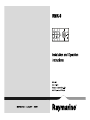
1
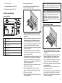
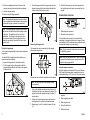
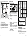
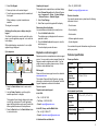
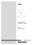
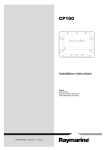
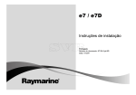
RMK-9
Installation and Operation
instructions
ENGLIS H
Da te : 04-2013
Docume nt numbe r: 81351-1-EN
© 2013 Ra yma rine UK Limite d
ENGLISH
Document number: 81351-1
Date: 04-2013
Handbook information
This handbook contains important information regarding
your product.
using the dedicated alternate power connector. The
keypad can be mounted horizontally or vertically with a
keypad mat for both orientations supplied.
A80217
This handbook includes information to help you:
RMK–9 keypad (Using
portrait keypad mat.)
• plan your installation and ensure you have all the
necessary equipment;
• install and connect your product as a part of your
system of Raymarine electronics;
A80217
This and other Raymarine product documentation
is available to download in PDF format from
www.raymarine.com.
RMK–9 keypad (Using
landscape keypad mat.)
Handbooks
Compatibility
The RayNet keypad has the following handbooks
available:
The multifunction displays shown below are compatible
with the RMK–9 keypad.
Handbooks
• New a Series
Description
Part number
• New c Series
Installation and operation
instructions
81351
• New e Series
• gS Series
87187
Product information
The RMK-9 is a remote control keypad for Raymarine
multifunction displays. The keypad is a class 1 PoE
device and can be powered using a suitable network
connection providing PoE or can be powered directly
This product is NOT approved for use in
hazardous/flammable atmospheres. Do
NOT install in a hazardous/flammable
atmosphere (such as in an engine room or
near fuel tanks).
Warning: Product grounding
• obtain support if required.
RMK-9 Mounting template
Warning: Potential ignition
source
Multifunction displays require software version 7.xx or
later.
Note: New a Series, New c Series and New e Series
displays cannot be powered on using the keypad.
Important information
Warning: Product installation
and operation
This product must be installed and operated
in accordance with the instructions
provided. Failure to do so could result in
personal injury, damage to your vessel
and/or poor product performance.
Before applying power to this product,
ensure it has been correctly grounded, in
accordance with the instructions in this
guide.
Warning: Positive ground
systems
Do not connect this unit to a system which
has positive grounding.
Warning: Switch off power
supply
Ensure the vessel’s power supply is
switched OFF before starting to install this
product. Do NOT connect or disconnect
equipment with the power switched on,
unless instructed in this document.
Caution: Power supply
protection
When installing this product ensure the
power source is adequately protected by
means of a suitably-rated fuse or automatic
circuit breaker.
3
Water ingress
• Raymarine specified cables are used.
Water ingress disclaimer
• Cables are not cut or extended, unless doing so is
detailed in the installation manual.
Although the waterproof rating capacity of this
product meets the IPX6 standard, water intrusion and
subsequent equipment failure may occur if the product
is subjected to commercial high-pressure washing.
Raymarine will not warrant products subjected to
high-pressure washing.
Disclaimer
Raymarine does not warrant that this product is
error-free or that it is compatible with products
manufactured by any person or entity other than
Raymarine.
Note: Where constraints on the installation
prevent any of the above recommendations,
always ensure the maximum possible separation
between different items of electrical equipment, to
provide the best conditions for EMC performance
throughout the installation
Declaration of conformity
Raymarine UK Ltd. declares that this product is
compliant with the essential requirements of EMC
directive 2004/108/EC.
Raymarine is not responsible for damages or injuries
caused by your use or inability to use the product, by the
interaction of the product with products manufactured
by others, or by errors in information utilized by the
product supplied by third parties.
The original Declaration of Conformity certificate
may be viewed on the relevant product page at
www.raymarine.com.
EMC installation guidelines
Product disposal
Raymarine equipment and accessories conform to
the appropriate Electromagnetic Compatibility (EMC)
regulations, to minimize electromagnetic interference
between equipment and minimize the effect such
interference could have on the performance of your
system
Dispose of this product in accordance with the WEEE
Directive.
Correct installation is required to ensure that EMC
performance is not compromised.
The Waste Electrical and Electronic Equipment
(WEEE) Directive requires the recycling of waste
electrical and electronic equipment. Whilst the WEEE
Directive does not apply to some Raymarine products,
we support its policy and ask you to be aware of how
to dispose of this product.
For optimum EMC performance we recommend that
wherever possible:
• Raymarine equipment and cables connected to it are:
– At least 1 m (3 ft) from any equipment transmitting
or cables carrying radio signals e.g. VHF radios,
cables and antennas. In the case of SSB radios,
the distance should be increased to 7 ft (2 m).
– More than 2 m (7 ft) from the path of a radar beam.
A radar beam can normally be assumed to spread
20 degrees above and below the radiating element.
• The product is supplied from a separate battery from
that used for engine start. This is important to prevent
erratic behavior and data loss which can occur if the
engine start does not have a separate battery.
4
IMO and SOLAS
The equipment described within this document is
intended for use on leisure marine boats and workboats
not covered by International Maritime Organization
(IMO) and Safety of Life at Sea (SOLAS) Carriage
Regulations.
Technical accuracy
To the best of our knowledge, the information in this
document was correct at the time it was produced.
However, Raymarine cannot accept liability for any
inaccuracies or omissions it may contain. In addition,
our policy of continuous product improvement may
change specifications without notice. As a result,
Raymarine cannot accept liability for any differences
between the product and this document. Please
check the Raymarine website (www.raymarine.com) to
ensure you have the most up-to-date version(s) of the
documentation for your product.
Parts supplied
The parts supplied with the keypad are shown below.
1
3
2
4
5
6
7
Warranty registration
To register your Raymarine product ownership, please
visit www.raymarine.com and register online.
8
D12712-1
It is important that you register your product to receive
full warranty benefits. Your unit package includes a
bar code label indicating the serial number of the unit.
You will need this serial number when registering your
product online. You should retain the label for future
reference.
1. Keypad.
2. Landscape keypad mat.
3. Portrait keypad mat.
4. Mounting gasket
5. 4 x mounting fixings.
RMK–9
6. Documentation pack.
Flush mounting the keypad
7. Right angled power cable 2 m (6.6 ft.).
For flush mounting you must rebate the mounting
surface to accommodate keypad.
Note: The appropriate tightening torque and drill bit
size to use depends on the thickness of the mounting
surface and the type of material it is made from.
8. RayNet network cable 2 m (6.6 ft.).
Note: The supplied gasket provides a seal between
the unit and a suitably flat and stiff mounting surface
or binnacle. The gasket should be used in all
installations. It may also be necessary to use a
marine-grade sealant if the mounting surface or
binnacle is not entirely flat and stiff or has a rough
surface finish.
Location and mounting
Keypad dimensions
C
D
Surface mounting the keypad
E
F
D12708-1
B
A
D12726-1
1. Check the selected location for the unit. A clear,
flat area with suitable clearance behind the panel
is required.
A
132.9 mm (5.23 in)
B
119 mm (4.7 in)
2. Before modifying the mounting surface, refer to the
dimensions supplied in this document to ensure
there is enough space for the unit and all cables.
C
18.7 mm (0.74 in)
3. Fix the supplied mounting template to the selected
location, using masking or self-adhesive tape.
D
8.5 mm (0.33 in)
4. Drill 4 holes as indicated on the mounting template
to accept the fixings.
E
37 mm (1.5 in)
F
90 mm (3.5 in.)
5. Using a suitable hole saw (the size and position
is indicated on the template), make a hole in each
corner of the cut-out area.
6. Using a suitable saw, cut along the inside edge of the
rear casing cut-out line indicated on the template.
7. Using a router follow the rebate cut-out line on the
template to cut out a rebate with a depth of 8.5 mm
(0.33 in), to accept the unit.
8. Ensure that the unit fits into the removed area and
then remove rough edges.
9. Place the supplied gasket onto the rear of the
keypad, ensuring the mounting holes are aligned.
10. Connect relevant cables.
11. Place the keypad into the rebate and secure using
the fixings provided.
D12722-1
1. Check the selected location for the unit. A clear,
flat area with suitable clearance behind the panel
is required.
2. Before modifying the mounting surface, refer to the
dimensions supplied in this document to ensure
there is enough space for the unit and cables.
3. Fix the supplied mounting template to the selected
location, using masking or self-adhesive tape.
4. Drill 4 holes as indicated on the mounting template
to accept the fixings.
5. Using a suitable hole saw, make a hole in each
corner of the cut-out area.
6. Using a suitable saw, cut along the inside edge of the
rear casing cut-out line indicated on the template.
7. Ensure that the unit fits into the removed area and
then remove rough edges.
5
8. Place the supplied gasket onto the rear of the
keypad, ensuring the mounting holes are aligned.
9. Connect relevant cables.
3. Close the opposite end of the keypad mat into the
keypad ensuring that the end tab and all side tabs
(shown below) click firmly into place.
10. Secure using the fixings provided.
4. With all 3 tabs along one side of the keypad free
the keypad mat should easily come away from the
keypad.
Connections overview
Note: The appropriate tightening torque and drill bit
size to use depends on the thickness of the mounting
surface and the type of material it is made from.
1
2
D12728-1
Note: The supplied gasket provides a seal between
the unit and a suitably flat and stiff mounting surface
or binnacle. The gasket should be used in all
installations. It may also be necessary to use a
marine-grade sealant if the mounting surface or
binnacle is not entirely flat and stiff or has a rough
surface finish.
1. Alternate power connector.
2. Network / power connector.
D12705-2
Removing the keypad mat
Fitting the keypad mat
Your keypad is supplied with a portrait and a landscape
keypad mat.
The keypad mat can be removed from the keypad
following the steps below.
1
2
The alternate power connector is required when
connecting to a network which does not support Power
over Ethernet PoE. The alternate power connector must
be connected directly to a power supply.
Note: Do not connect the alternate power connector
to a SeaTalkng network.
3
You should fit the keypad mat which matches your
chosen mounting orientation.
Note: Only use one power source. There is no need
to connect the alternate power connector when the
keypad is being supplied PoE.
1. Ensure the keypad mat is orientated correctly.
2. Fit the keypad mat into the keypad so that the
keypad mat tabs slide into the holes in the keypad,
as shown below.
D12713-2
Alternate power connection
When the keypad is not supplied Power over Ethernet
(PoE) then the alternate power connection should be
connected directly to a 12 V dc or 24 V dc power supply.
Locking tabs are located at the positions shown above.
Note: Take care and ensure the keypad housing
is not damaged
D12704-2
1. Using a thin bladed screwdriver insert the tip of the
screwdriver into the recess between the edge of the
keypad mat and the keypad housing at location (1)
shown above.
2. Gently push the screwdriver away and down from
the keypad mat to release the keypad mat tabs.
3. Repeat steps 1 and 2 for tabs at locations (2) and
(3).
1
3
2
5
4
D12729-1
1. Keypad.
2. Right angled power cable.
3. Black negative wire.
4. Ground / shield wire.
5. Red positive wire.
6
RMK–9
Warning: Product grounding
Before applying power to this product,
ensure it has been correctly grounded, in
accordance with the instructions in this
guide.
displays. If the network does not provide Power over
Ethernet (PoE) then the keypad must be powered
separately.
Network connection — gS Series multifunction
displays
1
Direct connection — gS Series multifunction display
2
2
1
Grounding — Dedicated drain wire
The power cable supplied with this product includes a
dedicated shield (drain) wire for connection to a vessel's
RF ground point.
It is important that an effective RF ground is connected
to the system. A single ground point should be used for
all equipment. The unit can be grounded by connecting
the shield (drain) wire of the power cable to the vessel's
RF ground point. On vessels without an RF ground
system the shield (drain) wire should be connected
directly to the negative battery terminal.
The dc power system should be either:
• Negative grounded, with the negative battery terminal
connected to the vessel's ground.
• Floating, with neither battery terminal connected to
the vessel's ground
3
3
D12702-2
1. gS Series multifunction display.
2. Keypad.
When connecting the keypad directly to a gS Series
multifunction display the keypad is supplied with PoE,
from the multifunction display.
D12709-2
1. gS Series multifunction display (supplying PoE to
the keypad).
Direct connection — Raymarine multifunction
display
2. Keypad.
1
2
3. Networked gS Series multifunction displays.
Warning: Positive ground
systems
3
Do not connect this unit to a system which
has positive grounding.
When connecting the keypad to a gS Series
multifunction display network the keypad is supplied
with PoE.
D12694-2
Keypad connection
The keypad can be connected directly to a multifunction
display’s network connector or via a network switch.
Multiple keypads can be connected to a system. Each
keypad can be used to control up to 4 multifunction
1. Multifunction display.
2. Keypad.
3. Right angled power cable.
When connecting the keypad directly to a New a Series,
New c Series or New e Series multifunction display the
keypad is not supplied with PoE, and so requires power
using the alternate power connector.
7
Network connection — Raymarine multifunction
displays
1
Keypad controls
Connecting the keypad allows you to control your
multifunction display remotely.
2
9
1
3
5
6
1
2
2
Display
State
Momentary
press
Press and
hold
1
Multifunction
display
Off
Power on*
—
On
Open
shortcuts
page
Power down
Multiple
multifunction
displays
All displays
Off
Power on all
displays*
—
All displays
On
Open
shortcuts
page on
active
display
Power down
all displays
1 Display On
and 1 display
Off
Open
shortcuts
page on
active
display
Power
down active
display
3
4
5
4
Configuration
6
7
8
9
10
11
10 7
8
3
4
D1271 1-1
1. Home — press to return to the homescreen.
2. Menu — accesses menus. Press again to close
menus.
3. UniControl — provides a rotary control and a
joystick with an OK push button for using menus
and applications.
4
D12697-3
4. Back — press to return to a previous menu or
dialog level.
1. Network switch.
5. Range Out — press to range out.
2. Keypad.
6. Range In — press to range in.
3. Right angled power cable.
7. Switch Active — press to switch the active pane,
or to switch the active multifunction display (in
multiple display systems).
4. Networked multifunction displays.
When connecting the keypad to a network switch the
keypad requires a separate power supply using the
alternate power connector.
Once connected the keypad must be paired with the
each multifunction display you want to control using
the keypad.
8. WPT / MOB — press and release to access the
waypoint options. Press again to place a waypoint.
Press and hold to place a Man Overboard (MOB)
marker at your current position.
9. Standby (Auto) — press to disengage integrated
autopilot, press and hold to activate Auto mode on
integrated autopilot.
10. Power — see table below:
8
Note: * Only applicable to gS Series displays.
New a Series, New c Series and New e Series
displays cannot be powered on using the
keypad.
Note: In a multiple display configuration where
displays are in different states the displays that
are turned off can only be turned on using the
power button on the display.
11. Joystick Up direction.
Pairing the keypad
The keypad can control 1 or more multifunction
displays. Multiple keypads can be connected to a
system. Each keypad can be paired with up to 4
multifunction displays.
With the keypad connected to the multifunction display:
1. Select External Keypad from the External Devices
menu: homescreen →Set-up →System Settings
→External Devices →External Keypad.
RMK–9
2. Select Pair Keypad.
3. Press any button on the external keypad.
4. From the pop-up message select the orientation of
the keypad.
Either landscape or portrait orientations are
available.
The keypad is now paired.
Switching the active pane or display using the
keypad
The Switch Active button is used to switch the active
pane on a multi application page and / or to switch the
active display.
With multiple displays connected and / or a multiple
application page displayed:
Cycle sequence
1
Unpairing the keypad
The keypad can be unpaired from an individual display.
1. Select External Keypad from the External Devices
menu: homescreen →Set-up →System Settings
→External Devices →External Keypad.
2. Select Clear Pairings.
3. Select Yes to unpair the keypad with the display.
Determining the active display
You can determine which display is currently active.
1. Press the Switch Active button.
The switcher pop-up is displayed on the screen or
pane that is active.
2. Press the Switch Active button again to close the
switcher pop-up.
The active display remains the same.
Raymarine customer support
2
3
Raymarine provides a comprehensive customer support
service. You can contact customer support through the
Raymarine website, telephone and e-mail. If you are
unable to resolve a problem, please use any of these
facilities to obtain additional help.
5
4
D12703-1
1. Press the Switch Active button to enter switch
mode.
2. Use the Rotary Control to cycle through the
available panes and / or displays.
Web support
Please visit the customer support area of our website at:
www.raymarine.com
This contains Frequently Asked Questions, servicing
information, e-mail access to the Raymarine Technical
Support Department and details of worldwide
Raymarine agents.
Telephone and e-mail support
In the USA:
• Tel: +1 603 324 7900
The keypad will cycle through displays in the order
in which they were paired. On multi application
pages the Range buttons can be used to switch the
active application between full and splitscreen.
3. Press the Back button or the Switch Active button
to exit switch mode.
• Toll Free: +1 800 539 5539
• E-mail: [email protected]
In the UK, Europe, and the Middle East:
• Tel: +44 (0)13 2924 6777
• E-mail: [email protected]
• Tel: +61 (0)29479 4800
• E-mail: [email protected]
Product information
If you need to request service, please have the following
information to hand:
• Product name.
• Product identity.
• Serial number.
• Software application version.
• System diagrams.
You can obtain this product information using the menus
within your product.
Technical specification
Power specification
PoE class
Class 1
Nominal supply
voltage
12 / 24 V dc
Operating
voltage range
10.8V dc to 31.2V dc
Power
consumption
3.84 W
Environmental specification
Operating
temperature
-25 ºC to +55 ºC (-13 ºF to 131 ºF)
Storage
temperature
-30 ºC to +70 ºC (-22 ºF to 158 ºF)
Relative humidity
Maximum 75%
Waterproof rating
IPX6
In Southeast Asia and Australia:
9
RayNet to RJ45 SeaTalkhs adapter cables
Wired connections
Network / power
1 x RayNet connector
Cable
Part number
• gS Series — 1000 Mb/s plus PoE.
1 m (3.28 ft) RayNet to RJ45
SeaTalkhs cable
A62360
3 m (9.84 ft) RayNet to RJ45
SeaTalkhs cable
A80151
10 m (32.8 ft) RayNet to RJ45
SeaTalkhs cable
A80159
400 mm (1.3 ft) RayNet to
RJ45 SeaTalkhs (female)
cable
A80160
• a, c, e Series — 100 Mb/s.
Alternate power
1 x Power connector.
Keypad spares
Item
Part number
Keypad mat spare (includes
landscape and portrait keypad
mat.)
R70185
Right angled power cable
A06070
Network cables
RayNet to RayNet cables
Cable
Part number
400 mm (1.3 ft) RayNet to
RayNet cable (female)
A80161
2 m (6.56 ft) RayNet to RayNet
cable (female)
A62361
5 m (16.4 ft) RayNet to RayNet
cable (female)
A80005
10 m (32.8 ft) RayNet to
RayNet cable (female)
A62362
20 m (65.6 ft) RayNet to
RayNet cable (female)
A80006
50 mm (1.97 in) RayNet to
RayNet cable (male)
A80162
RayNet right-angled coupler
A80262
RayNet cable puller 5-pack
R70014
10
RMK–9
www.ra ym a rin e .c o m