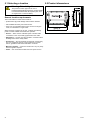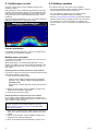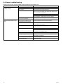
1
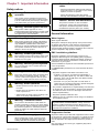
CP100
Installation instructions
English
Date: 07-2013
Document number: 87194-1-EN
© 2013 Raymarine UK Limited
Trademark and patents notice
Autohelm, hsb2, RayTech Navigator, Sail Pilot, SeaTalk, SeaTalkNG, SeaTalkHS and Sportpilot are registered trademarks of
Raymarine UK Limited. RayTalk, Seahawk, Smartpilot, Pathfinder and Raymarine are registered trademarks of Raymarine
Holdings Limited.
FLIR is a registered trademark of FLIR Systems, Inc. and/or its subsidiaries.
All other trademarks, trade names, or company names referenced herein are used for identification only and are the property
of their respective owners.
This product is protected by patents, design patents, patents pending, or design patents pending.
Fair Use Statement
You may print no more than three copies of this manual for your own use. You may not make any further copies or distribute or use
the manual in any other way including without limitation exploiting the manual commercially or giving or selling copies to third parties.
Software updates
Check the website www.raymarine.com for the latest software releases for your product.
Product handbooks
The latest versions of all English and translated handbooks are available to download in PDF format from the website www.raymarine.com.
Please check the website to ensure you have the latest handbooks.
Copyright ©2013 Raymarine UK Ltd. All rights reserved.
ENGLISH
Document number: 87194-1
Date: 07-2013
Contents
Chapter 1 Important information........................ 7
10.3 Network cable connector types............................ 45
Safety notices............................................................ 7
General Information ................................................... 7
10.4 Network cables .................................................. 45
10.5 SeaTalkng cables and accessories ....................... 46
Chapter 2 Handbook and product
information........................................................... 9
2.1 Handbook information .......................................... 10
2.2 Product overview ................................................. 10
2.3 CHIRP Sonar overview......................................... 11
2.4 CHIRP DownVision overview ................................ 11
Chapter 3 Planning the installation ................... 13
3.1 Installation checklist ............................................. 14
3.2 Parts supplied...................................................... 14
3.3 Required additional components ........................... 15
3.4 Compatible multifunction displays ......................... 15
3.5 Compatible transducers........................................ 16
3.6 Typical systems ................................................... 16
3.7 Tools ................................................................... 17
Chapter 4 Cables and connections.................... 19
4.1 General cabling guidance ..................................... 20
4.2 Connections overview .......................................... 20
4.3 Power connection ................................................ 21
4.4 Transducer connection ......................................... 22
4.5 Network connection.............................................. 23
Chapter 5 Location and mounting ..................... 25
5.1 Selecting a location .............................................. 26
5.2 Product dimensions.............................................. 26
5.3 Mounting ............................................................. 27
Chapter 6 System checks and
troubleshooting ................................................... 29
6.1 Initial power on test .............................................. 30
6.2 Software updates ................................................. 30
6.3 Troubleshooting ................................................... 31
6.4 Sonar troubleshooting .......................................... 32
6.5 LED indications.................................................... 33
6.6 Resetting the sonar module .................................. 34
Chapter 7 Maintenance ....................................... 35
7.1 Routine checks .................................................... 36
7.2 Unit cleaning instructions ...................................... 36
7.3 Transducer care and cleaning ............................... 37
Chapter 8 Technical support .............................. 39
8.1 Raymarine customer support ................................ 40
8.2 Viewing product information .................................. 40
Chapter 9 Technical specification...................... 41
9.1 Technical specification.......................................... 42
Chapter 10 Options and accessories ................ 43
10.1 Spares and accessories...................................... 44
10.2 Network hardware .............................................. 44
5
6
CP100
Chapter 1: Important information
Safety notices
Warning: Product installation and
operation
This product must be installed and operated in
accordance with the instructions provided. Failure
to do so could result in personal injury, damage to
your vessel and/or poor product performance.
Warning: Potential ignition source
Caution: Do not cut transducer
cables
• Cutting the transducer cable severely reduces
sonar performance. If the cable is cut, it must be
replaced, it cannot be repaired.
• Cutting the transducer cable will void the
warranty and invalidate the European CE mark.
Caution: Service and maintenance
This product contains no user serviceable
components. Please refer all maintenance
and repair to authorized Raymarine dealers.
Unauthorized repair may affect your warranty.
This product is NOT approved for use in
hazardous/flammable atmospheres. Do NOT install
in a hazardous/flammable atmosphere (such as in
an engine room or near fuel tanks).
General Information
Warning: High voltage
Water ingress
This product contains high voltage. Adjustments
require specialized service procedures and tools
only available to qualified service technicians.
There are no user serviceable parts or adjustments.
The operator should never remove the cover or
attempt to service the product.
Although the waterproof rating capacity of this product meets
the IPX6 & IPX7 standard, water intrusion and subsequent
equipment failure may occur if the product is subjected to
commercial high-pressure washing. Raymarine will not warrant
products subjected to high-pressure washing.
Warning: Product grounding
EMC installation guidelines
Before applying power to this product, ensure it has
been correctly grounded, in accordance with the
instructions in this guide.
Raymarine equipment and accessories conform to the
appropriate Electromagnetic Compatibility (EMC) regulations,
to minimize electromagnetic interference between equipment
and minimize the effect such interference could have on the
performance of your system
Warning: Positive ground systems
Do not connect this unit to a system which has
positive grounding.
Warning: Switch off power supply
Water ingress disclaimer
Correct installation is required to ensure that EMC performance
is not compromised.
For optimum EMC performance we recommend that wherever
possible:
• Raymarine equipment and cables connected to it are:
Ensure the vessel’s power supply is switched OFF
before starting to install this product. Do NOT
connect or disconnect equipment with the power
switched on, unless instructed in this document.
– At least 1 m (3 ft) from any equipment transmitting or
cables carrying radio signals e.g. VHF radios, cables and
antennas. In the case of SSB radios, the distance should
be increased to 7 ft (2 m).
Warning: Sonar operation
– More than 2 m (7 ft) from the path of a radar beam. A
radar beam can normally be assumed to spread 20 degrees
above and below the radiating element.
• NEVER operate the sonar with the vessel out of
the water.
• NEVER touch the transducer face when the
sonar is powered on.
• SWITCH OFF the sonar if divers are likely to be
within 7.6 m (25 ft) of the transducer.
Warning: Transducer cables
Do not remove the transducer cable whilst the
product is powered on, doing so can cause sparks.
If the transducer cable is accidently removed whilst
the product is powered on, switch the product's
power off, replace the cable and then switch the
power back on.
• The product is supplied from a separate battery from that used
for engine start. This is important to prevent erratic behavior
and data loss which can occur if the engine start does not
have a separate battery.
• Raymarine specified cables are used.
• Cables are not cut or extended, unless doing so is detailed in
the installation manual.
Note: Where constraints on the installation prevent
any of the above recommendations, always ensure the
maximum possible separation between different items of
electrical equipment, to provide the best conditions for EMC
performance throughout the installation
Suppression ferrites
Caution: Power supply protection
When installing this product ensure the power
source is adequately protected by means of a
suitably-rated fuse or automatic circuit breaker.
Raymarine cables may be fitted with suppression ferrites. These
are important for correct EMC performance. If a ferrite has to be
removed for any purpose (e.g. installation or maintenance), it
must be replaced in the original position before the product is
used.
Use only ferrites of the correct type, supplied by Raymarine
authorized dealers.
Important information
7
Connections to other equipment
Requirement for ferrites on non-Raymarine cables
If your Raymarine equipment is to be connected to other
equipment using a cable not supplied by Raymarine, a
suppression ferrite MUST always be attached to the cable near
the Raymarine unit.
Declaration of conformity
Raymarine UK Ltd. declares that this product is compliant with
the essential requirements of EMC directive 2004/108/EC.
The original Declaration of Conformity certificate may be viewed
on the relevant product page at www.raymarine.com.
Product disposal
Dispose of this product in accordance with the WEEE Directive.
The Waste Electrical and Electronic Equipment (WEEE)
Directive requires the recycling of waste electrical and electronic
equipment. Whilst the WEEE Directive does not apply to some
Raymarine products, we support its policy and ask you to be
aware of how to dispose of this product.
Warranty registration
To register your Raymarine product ownership, please visit
www.raymarine.com and register online.
It is important that you register your product to receive full
warranty benefits. Your unit package includes a bar code label
indicating the serial number of the unit. You will need this serial
number when registering your product online. You should retain
the label for future reference.
IMO and SOLAS
The equipment described within this document is intended for
use on leisure marine boats and workboats not covered by
International Maritime Organization (IMO) and Safety of Life at
Sea (SOLAS) Carriage Regulations.
Technical accuracy
To the best of our knowledge, the information in this document
was correct at the time it was produced. However, Raymarine
cannot accept liability for any inaccuracies or omissions it
may contain. In addition, our policy of continuous product
improvement may change specifications without notice. As a
result, Raymarine cannot accept liability for any differences
between the product and this document. Please check the
Raymarine website (www.raymarine.com) to ensure you have
the most up-to-date version(s) of the documentation for your
product.
8
CP100
Chapter 2: Handbook and product information
Chapter contents
•
2.1 Handbook information on page 10
•
2.2 Product overview on page 10
•
2.3 CHIRP Sonar overview on page 11
•
2.4 CHIRP DownVision overview on page 11
Handbook and product information
9
2.1 Handbook information
2.2 Product overview
This handbook contains important information related to the
installation of the CP100 sonar module.
The CP100 is a CHIRP sonar module with DownVision
capabilities. In conjunction with a compatible multifunction
display, the CP100 provides a detailed view of the water’s
bottom structure, enabling you to identify fish and other objects
in the water underneath your vessel.
The handbook includes information to help you:
• plan your installation and ensure you have all the necessary
equipment;
• install and connect the CP100 as part of a wider system of
connected marine electronics;
• troubleshoot problems and obtain technical support if required.
This and other Raymarine product documents are available to
download in PDF format from www.raymarine.com.
Related products
This document is applicable to the following product:
Part number
Name
Description
E70204
CP100
2–channel
CHIRP /
DownVision
sonar module
E70205
CP100 and
CPT-100
2–channel
CHIRP /
DownVision
sonar module
and DownVision
transom
transducer.
D12932-1
The CP100 has the following features:
• Dual-beam sonar (conical beam and fan beam).
• Typical depth performance of 600 ft.
• Water temperature sensing.
• Support for transom or through-hull DownVision transducers.
• Low power consumption.
• 12 V or 24 V operation.
Product documentation
The following documentation is applicable to your product:
Description
Part number
CP100 Installation instructions
Installation of a CP100 unit and connection to a wider
system of marine electronics.
87194 / 88022
CP100 Mounting template
Mounting diagram for surface mounting a CP100 unit.
87193
CPT–100 Transom transducer Installation
instructions
Installation of a DownVision transom-mount transducer.
87197 / 88024
CPT–110 / CPT-120 Through-hull transducer
Installation instructions
Installation of a DownVision through-hull transducer.
87201 / 88025
New a Series, c Series, e Series Installation and
operation instructions
Details the operation of the fishfinder application
(including DownVision operation) for New a Series, c
Series, e Series multifunction displays.
81337
• Waterproof to IPX 6 and IPX 7.
• Robust and waterproof high-speed network connection.
Further information
For detailed operating instructions, refer to the handbook that
accompanies your multifunction display.
Transducer installation instructions
This document includes installation instructions for the sonar
module only. For installation instructions for a connected
transducer, please refer to the documentation that accompanies
the transducer.
10
CP100
2.3 CHIRP Sonar overview
2.4 CHIRP DownVision overview
Sonar interprets signals from the transducer and builds up a
detailed underwater view. The transducer sends pulses of
sound waves into the water and measures the time it takes for
the sound wave to travel to the bottom and back. The returning
echoes are affected by bottom structure and by any other objects
in their path, for example reefs, wrecks, shoals or fish.
DownVision interprets signals from the transducer and builds up
a detailed underwater view. The transducer sends pulses of
sound waves into the water and measures the time it takes for
the sound wave to travel to the bottom and back. The returning
echoes are affected by bottom structure and by any other objects
in their path, for example reefs, wrecks, shoals or fish.
Sonar produces a 25° conical shaped beam, the coverage of the
conical beam is the water column directly beneath the vessel.
DownVision produces a wide–angle side-to-side beam and a
thin fore-to-aft beam. The coverage of the DownVision beam is
a water column directly beneath and to the sides of the vessel.
Conical beam
DownVision beam
D12784-1
Sonar is effective at a range of speeds. In deeper waters the
CHIRP bandwidth is automatically restricted to improve bottom
lock and the detection of moving objects (e.g. fish) in the wider
water column.
CHIRP sonar screen example
D12777-1
DownVision is effective at lower vessel speeds. In deeper
waters the CHIRP bandwidth is automatically restricted to
improve bottom lock and the detection of moving objects (e.g.
fish) in the wider water column.
The wide, thin beam produces clear target returns. The use of
CHIRP processing and a higher operating frequency provide
a more detailed image, making it easier to identify bottom
structures around which fish may reside.
CHIRP DownVision screen example
Handbook and product information
11
12
CP100
Chapter 3: Planning the installation
Chapter contents
•
3.1 Installation checklist on page 14
•
3.2 Parts supplied on page 14
•
3.3 Required additional components on page 15
•
3.4 Compatible multifunction displays on page 15
•
3.5 Compatible transducers on page 16
•
3.6 Typical systems on page 16
•
3.7 Tools on page 17
Planning the installation
13
3.1 Installation checklist
3.2 Parts supplied
Installation includes the following activities:
Installation Task
1
Plan your system.
2
Obtain all required equipment and tools.
3
Site all equipment.
4
Route all cables.
5
Drill cable and mounting holes.
6
Make all connections into equipment.
7
Secure all equipment in place.
8
Power on and test the system.
2
1
3
4
Schematic diagram
D12934-1
A schematic diagram is an essential part of planning any
installation. It is also useful for any future additions or
maintenance of the system. The diagram should include:
• Location of all components.
• Connectors, cable types, routes and lengths.
14
Item
Description
Quantity
1
Sonar module.
1
2
Documentation pack.
1
3
Screw.
4
4
Power cable 1 m (3.28 ft).
1
CP100
3.3 Required additional components
3.4 Compatible multifunction displays
This product forms part of a system of electronics and requires
the following additional components for full operation.
This product is compatible with the following Raymarine
multifunction displays.
• Compatible DownVision transducer; transom or through-hull
mount. Refer to 3.5 Compatible transducers for a list of
compatible products.
• New a Series, New c Series, New e Series.
• gS Series.
• Compatible Raymarine multifunction display. Refer to 3.4
Compatible multifunction displays for a list of compatible
products.
• Data cables. Refer to Chapter 4 Cables and connections
for suitable cables. Some installations may also require
extensions to data, power or transducer cables. Refer to the
Chapter 4 Cables and connections and Chapter 10 Options
and accessories sections for more information.
Planning the installation
15
3.5 Compatible transducers
3.6 Typical systems
This product is compatible with the following Raymarine
transducers.
Example: basic sonar system featuring multifunction
display
Part
number
Description
Mounting
Type
Construction
A80270
CPT-100
DownVision
transducer
Transom
Plastic
A80277
CPT-110
DownVision
transducer
Throughhull
Plastic
CPT-120
DownVision
transducer
Throughhull
A80271
2
1
Bronze
3
4
D12937-1
Item
Description
Part number
1
Multifunction display
Refer to your dealer for all
compatible variants.
2
Sonar module
Refer to Related products.
3
RayNet cable
Refer to 10.4 Network
cables for RayNet cables.
4
DownVision transducer
Refer to 3.5 Compatible
transducers.
Example: expanded sonar system featuring autopilot
system and multifunction display
2
2
3
RayNet
RayNet
1
5
4
6
7
9
SeaTalkng
8
10
0
SeaTalkng
D12938-1
16
CP100
Item
Description
Part number
3.7 Tools
1
Sonar module
Refer to Related products.
Installation of the unit requires the following tools:
2
RayNet cables
Refer to 10.4 Network
cables for RayNet cables.
3
RayNet network switch
A80007
4
Radar scanner
Refer to your dealer for all
applicable part numbers.
5
Multifunction display
Refer to your dealer for all
applicable part numbers.
6
DownVision transducer
Refer to 3.5 Compatible
transducers.
7
Evolution ACU
Refer to your dealer for all
applicable part numbers.
8
SeaTalkng spur cable
Refer to 10.5 SeaTalkng
cables and accessories.
9
Evolution EV
Refer to your dealer for all
applicable part numbers.
10
Pilot head controller
Refer to your dealer for all
applicable part numbers.
1
2
3
4
D12228-2
Item
Description
1
Drill
2
Pozidrive screwdriver
3
Drill bit of appropriate size*
4
Adhesive tape
Note: *Drill bit size is dependent on the thickness and type of
material that the unit is to be mounted on.
Planning the installation
17
18
CP100
Chapter 4: Cables and connections
Chapter contents
•
4.1 General cabling guidance on page 20
•
4.2 Connections overview on page 20
•
4.3 Power connection on page 21
•
4.4 Transducer connection on page 22
•
4.5 Network connection on page 23
Cables and connections
19
4.1 General cabling guidance
4.2 Connections overview
Cable types and length
It is important to use cables of the appropriate type and length
• Unless otherwise stated use only standard cables of the
correct type, supplied by Raymarine.
• Ensure that any non-Raymarine cables are of the correct
quality and gauge. For example, longer power cable runs may
require larger wire gauges to minimize voltage drop along the
run.
Routing cables
1
Cables must be routed correctly, to maximize performance and
prolong cable life.
• Do NOT bend cables excessively. Wherever possible, ensure
a minimum bend diameter of 200 mm (8 in) / minimum bend
radius of 100 mm (4 in).
2
3
D12939-1
1. Network.
2. Power (12 V / 24 V dc).
3. Transducer.
Making connections
200 mm (8 in)
100 mm (4 in)
• Protect all cables from physical damage and exposure to heat.
Use trunking or conduit where possible. Do NOT run cables
through bilges or doorways, or close to moving or hot objects.
• Secure cables in place using tie-wraps or lacing twine. Coil
any extra cable and tie it out of the way.
Follow the steps below to connect network, transducer and
power cables to your unit.
1. Ensure that the vessel's power supply is switched off.
2. Ensure that the device being connected to the unit has
been installed in accordance with the installation instructions
supplied with that device.
3. Ensuring correct orientation push the cable connector fully
onto the corresponding connector on the unit.
4. Turn the locking collar clockwise to secure the cables.
• Where a cable passes through an exposed bulkhead or
deckhead, use a suitable watertight feed-through.
• Do NOT run cables near to engines or fluorescent lights.
Always route data cables as far away as possible from:
• other equipment and cables,
• high current carrying ac and dc power lines,
• antennae.
Strain relief
Ensure adequate strain relief is provided. Protect connectors
from strain and ensure they will not pull out under extreme sea
conditions.
Circuit isolation
Appropriate circuit isolation is required for installations using
both AC and DC current:
• Always use isolating transformers or a separate power-inverter
to run PC’s, processors, displays and other sensitive electronic
instruments or devices.
• Always use an isolating transformer with Weather FAX audio
cables.
• Always use an isolated power supply when using a 3rd party
audio amplifier.
• Always use an RS232/NMEA converter with optical isolation
on the signal lines.
• Always make sure that PC’s or other sensitive electronic
devices have a dedicated power circuit.
Cable shielding
Ensure that all data cables are properly shielded that the
cable shielding is intact (e.g. hasn’t been scraped off by being
squeezed through a tight area).
20
CP100
4.3 Power connection
Warning: Do NOT connect a
SeaTalkng backbone to a 24 V power
supply.
Always use the power cable provided with your product.
To avoid possible damage to equipment, do
NOT use the supplied power cable to connect a
SeaTalkng backbone to a 24 V power supply.
Warning: Do NOT power this
product from a SeaTalkng backbone
To avoid possible damage to equipment, do NOT
use a SeaTalkng backbone as the power source for
this product.
Power cable extension
1
The product is supplied with a power cable, which can be
extended if required.
2
3
D12237-3
Item
Description
1
RED positive wire
2
Ground
3
BLACK negative wire
1
• The power cable for each unit in your system should be run as
a separate, single length of 2-wire cable from the unit to the
vessel's battery or distribution panel.
• Raymarine recommends a minimum wire gauge of 18AWG
(0.82 mm2) for any length of cable extension.
• Regardless of the length of the cable extension, any cable
used should be capable of achieving a minimum voltage at
the unit of 10.8 V with a fully flat battery at 11 V.
Breakers, fuses and circuit protection
2
It is recommended that you fit a thermal breaker or fuse at the
distribution panel.
Thermal breaker rating
5 A (if only connecting one device)
Note: The suitable fuse rating for the thermal breaker is
dependent on the number of devices you are connecting. If in
doubt consult an authorized Raymarine dealer.
3
4
Sharing a breaker
D12238-1
Item
Description
1
Power supply
2
Sonar module
3
Vessel's RF ground
4
Transducer
Where more than 1 piece of equipment shares a breaker you
must provide protection for the individual circuits. E.g. by
connecting an in-line fuse for each power circuit.
-
+
1
2
3
The unit is intended for use on dc 'negative' or 'floating' ground
power systems rated from 10.2V to 32V.
Raymarine recommends that all power connections are made
via a distribution panel. All equipment must be either:
• powered from a circuit breaker or switch, with 5A circuit
protection, or
• powered from a 5A slow blow in-line fuse connected to the
RED positive wire of the power cable.
4
The unit does not have a power switch. The unit is powered
when the power cable is attached to the vessel's power supply.
4
D11637-2
Note: The unit should be mounted so that the power cable
can be easily removed if necessary. If the unit is placed in a
difficult to reach location, Raymarine recommends installing
an on/off switch on the power connection at a point that is
easily accessible.
1
Positive (+) bar
2
Negative (-) bar
3
Circuit breaker
4
Fuse
Where possible, connect individual items of equipment to
individual circuit breakers. Where this is not possible, use
individual in-line fuses to provide the necessary protection.
Cables and connections
21
Warning: Product grounding
Before applying power to this product, ensure it has
been correctly grounded, in accordance with the
instructions in this guide.
Grounding — Dedicated drain wire
4.4 Transducer connection
This product is designed for use with DownVision transducers.
• Refer to 3.5 Compatible transducers for a list of compatible
transducers.
• Transducers must be installed in accordance with the
instructions provided with the transducer.
The power cable supplied with this product includes a dedicated
shield (drain) wire for connection to a vessel's RF ground point.
It is important that an effective RF ground is connected to the
system. A single ground point should be used for all equipment.
The unit can be grounded by connecting the shield (drain) wire
of the power cable to the vessel's RF ground point. On vessels
without an RF ground system the shield (drain) wire should be
connected directly to the negative battery terminal.
1
The dc power system should be either:
• Negative grounded, with the negative battery terminal
connected to the vessel's ground.
2
• Floating, with neither battery terminal connected to the
vessel's ground
Warning: Positive ground systems
3
D12940-1
Do not connect this unit to a system which has
positive grounding.
1. Sonar module.
2. Transducer cable (supplied with transducer).
3. DownVision transducer.
Warning: Transducer cables
Do not remove the transducer cable whilst the
product is powered on, doing so can cause sparks.
If the transducer cable is accidently removed whilst
the product is powered on, switch the product's
power off, replace the cable and then switch the
power back on.
Caution: Do not cut transducer
cables
• Cutting the transducer cable severely reduces
sonar performance. If the cable is cut, it must be
replaced, it cannot be repaired.
• Cutting the transducer cable will void the
warranty and invalidate the European CE mark.
Transducer cable extension
For some installations it may be necessary to extend the
transducer cable.
• Refer to Chapter 10 Options and accessories for a list of
suitable transducer extension cables.
• Raymarine recommends a maximum of one cable extension
for any single transducer cable.
• For best performance, keep all cable lengths to a minimum.
22
CP100
4.5 Network connection
1
The unit must be connected to a compatible Raymarine
multifunction display to enable echo sounder data to be viewed.
Multifunction display connection
Unit connected to a multifunction display using a RayNet cable.
2
3
4
5
1
2
2
2
3
D12236-3
D12234-3
Note: The connection panel on your product may look
slightly different to that shown, depending on variant. The
network connection method remains the same for all products
featuring RayNet connectors.
Note: The connection panel on your product may look
slightly different to that shown, depending on variant. The
network connection method remains the same for all products
featuring RayNet connectors.
Item
Description
1
Sonar module.
Item
Description
2
RayNet cable.
1
Sonar module.
3
RayNet network switch.
2
Connector panel for compatible Raymarine multifunction
display.
4
Connector panel for compatible Raymarine multifunction
display.
3
RayNet cable.
5
Connector panel for additional compatible Raymarine
multifunction display.
Multifunction display configuration (extended cables)
When the required length of a single network cable run is greater
than 20 m (65.6 ft), a RayNet (male) to (male) adaptor cable
should be used to connect RayNet cables together .
For details on available network hardware and cables refer to
Chapter 10 Options and accessories.
1
2
3
Note: Ensure network cables and connections are tight
and secure using any cable ties provided with your network
hardware.
3
4
D12942-1
Note: The connection panel on your product may look
slightly different to that shown, depending on variant. The
network connection method remains the same for all products
featuring RayNet connectors.
Item
Description
1
Sonar module.
2
Connector panel for compatible Raymarine multifunction
display.
3
RayNet cables.
4
RayNet (Male) to (Male) adaptor cable.
Multiple multifunction display configuration
A Raymarine network switch can be used to connect the unit to
more than 1 multifunction display.
Cables and connections
23
24
CP100
Chapter 5: Location and mounting
Chapter contents
•
5.1 Selecting a location on page 26
•
5.2 Product dimensions on page 26
•
5.3 Mounting on page 27
Location and mounting
25
5.1 Selecting a location
5.2 Product dimensions
Warning: Potential ignition source
72 mm (2.8 in)
General location requirements
The unit should be mounted where it will be:
171 mm (6.7 in)
162 mm (6.4 in)
This product is NOT approved for use in
hazardous/flammable atmospheres. Do NOT install
in a hazardous/flammable atmosphere (such as in
an engine room or near fuel tanks).
• protected from physical damage and excessive vibration.
• well ventilated and away from heat sources.
• away from any potential ignition source such as an engine
room, near fuel tanks or a gas locker.
When choosing a location for the unit, consider the following
points to ensure reliable and trouble-free operation:
205 mm (8.1 in)
225 mm (8.9 in)
D12941-1
• Access — there must be sufficient space to enable cable
connections to the unit, avoiding tight bends in the cable.
• Diagnostics — the unit must be mounted in a location where
the diagnostics LED is easily visible.
• Interference — the unit should be mounted far enough away
from any equipment that may cause interference such as
motors, generators and radio transmitters / receivers.
• Magnetic compass — mount the unit at least 1 m (3 ft.) away
from a magnetic compass.
• Power — the unit must be located near a dc power source.
26
CP100
5.3 Mounting
Mounting the unit
Having chosen a suitable location, install the unit as follows:
Note: Raymarine recommends mounting the unit vertically.
1. Secure the mounting template in the required location using
adhesive tape.
Ra
ym
ar in
e CS
22
digi
ta l
C S2
so
un
2 Te
de
rm
od
ule
m
ou
nt in
g te
m pl
at e
m pl
at e
UP
108.2 mm (4.26 in)
421
IM
PO
en RTAN
su re
276
printT: Th is
.8 mm
ed do cu
(10
tem m
.90
299
pla en t
in)
.4 mm
te
m ay
(11
m atc
.78
no
he t pr
in)
s th int
e m tru
ea su e to
rem scale
en . Be
ts pr for
ov e m
ide od
d.
ifying
m ou
nt ing
su rfa
188.0 mm (7.40 in)
Doc
Dat um ent
e: 07- num
201 ber
1
: 871
34.6 mm (1.36 in)
Pilo
t hol
(4 pos
e
itio center
ns)
ce ,
D12
197
-1
D12240-1
2. Drill 4 holes at the marked location on the template.
Ra
ym
ar in
e CS
22
digi
ta l
C S2
so
un
2 Te
de
rm
od
ule
m
ou
nt in
g te
m pl
at e
m pl
at e
UP
108.2 mm (4.26 in)
421
IM
PO
en RTAN
su re
276
printT: Th is
.8 mm
ed do cu
(10
tem m
.90
299
pla en t
in)
.4 mm
te
m ay
(11
m atc
.78
no
he t pr
in)
s th int
e m tru
ea su e to
rem scale
en . Be
ts pr for
ov e m
ide od
d.
ifying
m ou
nt ing
su rfa
188.0 mm (7.40 in)
Doc
Dat um ent
e: 07- num
201 ber
1
: 871
34.6 mm (1.36 in)
Pilo
t hol
(4 pos
e
itio center
ns)
ce ,
D12
197
-1
D12241-1
3. Remove the mounting template.
4. Screw in the supplied fixing screws about half way into the
holes.
5. Place the unit onto the fixing screws.
6. Push the unit down to engage the key slots in the unit.
7. Tighten the screws
1
2
3
D12242-1
Note: Drill bit, tap size and tightening torque is dependent on
the thickness and type of material the unit is to be mounted on.
Location and mounting
27
28
CP100
Chapter 6: System checks and troubleshooting
Chapter contents
•
6.1 Initial power on test on page 30
•
6.2 Software updates on page 30
•
6.3 Troubleshooting on page 31
•
6.4 Sonar troubleshooting on page 32
•
6.5 LED indications on page 33
•
6.6 Resetting the sonar module on page 34
System checks and troubleshooting
29
6.1 Initial power on test
6.2 Software updates
Once the unit has been correctly installed check that it is
operating correctly.
The software running on the product can be updated.
After powering on, the unit will take approximately 50 seconds
to bootup, from powering on through to normal operation LED
status indicator should be GREEN. If the LED status indicator
is not green then refer to the troubleshooting section of this
handbook.
Open the Fishfinder application on your connected multifunction
display and ensure that it is operating correctly.
• Raymarine periodically releases software updates to improve
product performance and add new features.
• You can update the software for your product using a
connected and compatible multifunction display.
• Refer to www.raymarine.com/software/ for the latest software
updates and the software update procedure for your product.
• If in doubt as to the correct procedure for updating your
product software, refer to your dealer or Raymarine technical
support.
Further information
For detailed operating instructions, refer to the handbook that
accompanies your multifunction display.
Multiple sonar operation
For systems with multiple sonar modules, only one sonar may
operate at any one time.
Before attempting to use the fishfinder application on your
multifunction display, use one of the methods described in this
document to ensure that only one sonar module is active on
your system.
Switching between internal and external sonar modules
If you want to switch your active sonar module between internal
and external follow the steps below.
1. Power off the active sonar module.
• Internal sonar module is turned off from the Fishfinder
application menu: Menu > Set-up > Sounder Set-up >
Internal Sounder.
• External sonar modules should be turned off at the power
supply.
2. Wait for the No Sounder Source Available message to be
displayed in the Fishfinder application.
3. Power on the new sonar module.
Switching between multiple external sonar modules
If your system includes multiple external sonar modules you
must complete the procedure detailed below to ensure only one
sonar module is active at a time.
Note: If your multifunction display has an internal sonar
module, complete the procedure detailed in Switching
between internal and external sonar modules BEFORE
attempting the following:
1. Power off ALL external sonar modules, either at the power
supply or by disconnecting the power cable from the sonar
module.
2. Wait for the No Sounder Source Available message to be
displayed in the Fishfinder application.
3. Power on the external sonar module that you want to use.
30
CP100
6.3 Troubleshooting
The troubleshooting information provides possible causes and
corrective action required for common problems associated with
marine electronics installations.
All Raymarine products are, prior to packing and shipping,
subjected to comprehensive test and quality assurance
programs. However, if you experience problems with the
operation of your product this section will help you to diagnose
and correct problems in order to restore normal operation.
If after referring to this section you are still having problems
with your unit, please contact Raymarine Technical Support for
further advice.
System checks and troubleshooting
31
6.4 Sonar troubleshooting
Problems with the sonar and their possible causes and solutions are described here.
Problem
Possible causes
Possible solutions
Sonar data not available on
multifunction display.
Unit power supply fault.
Check the unit power supply and cables.
Other unit fault.
Refer to the instructions supplied with the unit.
SeaTalkhs / RayNet network problem.
Check that the unit is correctly connected to a Raymarine network
switch. If a crossover coupler or other coupler cable / adapter is used,
check all connections (as applicable).
Check the status of the Raymarine network switch (if applicable).
Check that SeaTalkhs/ RayNet cables are free from damage.
Problematic depth readings or sonar
image.
Software mismatch between equipment
may prevent communication.
Contact Raymarine technical support.
Gain or Frequency settings may be
inappropriate for present conditions.
Check the sonar presets, gain and frequency settings.
Unit power supply fault.
Check the voltage from the power supply, if this is too low it can affect
the transmitting power of the unit.
Unit cable fault.
Ensure that the power, transducer and all other cables to the unit are
properly connected and free from damage.
Transducer fault.
Check that the transducer is mounted correctly and is clean.
If you have a transom mount transducer, check that the transducer
hasn't kicked-up due to hitting an object.
32
Other unit fault.
Refer to the instructions supplied with the unit.
Vessel stationary.
Fish arches are not displayed if the vessel is stationary; fish will appear
on the display as straight lines.
High vessel speed
Turbulence around the transducer may be confusing the unit.
Scroll speed set to zero
Adjust the scroll speed.
CP100
6.5 LED indications
The power LED for this product has a number of flashing (blinking) modes to provide status information for diagnostics and
troubleshooting.
LED color
LED code
Status
User action
Solid Green
Power On
• None (normal power up takes <1 minute.)
Green 1 blink
Normal operation
• None
Amber 1
blink
Transducer
disconnected
• Ensure transducer cable and connections are secure and
free from damage.
• Power cycle unit to recover transducer information.
• If problem persists contact Raymarine technical support.
Amber 2
blinks
No network
detected
• Ensure network is powered.
• Ensure network cable and connections are secure and free
from damage.
• If problem persists contact Raymarine technical support.
Amber 5
blinks
Under voltage
(<10.2V)
• Ensure power cable and connections are secure and free
from damage.
• Ensure power supply cabling is consistent with
recommendations.
• If problem persists contact Raymarine technical support.
Amber 6
blinks
Over voltage
(>34.2V)
• Ensure power supply levels are consistent with
recommendations.
• If problem persists contact Raymarine technical support.
Red 1 blink
General failure
• If combined with voltage warning, check power supply and
cables.
• Power-cycle the unit.
• If problem persists contact Raymarine technical support.
Red 3 blinks
Unit overheating
• Ensure installation environment is within recommendations.
• Unit will stop pinging and then start again once normal
operating temperature is achieved.
• If problem persists contact Raymarine technical support.
Red 4 blinks
Problems with
internal database
• Power-cycle the unit.
• If problem persists contact Raymarine technical support.
Note: If any other LED sequence other than described above is seen and persists please contact Raymarine technical support.
System checks and troubleshooting
33
6.6 Resetting the sonar module
You can use the reset function on a compatible Raymarine
multifunction display to restore the sonar module to its factory
default settings.
In
1.
2.
3.
4.
5.
the fishfinder application:
Select Menu.
Select Set-up.
Select Sounder Set-up.
Select Sonar Reset.
Select Yes to confirm or No to abort the operation, as
appropriate.
The unit will now be reset to factory default settings.
34
CP100
Chapter 7: Maintenance
Chapter contents
•
7.1 Routine checks on page 36
•
7.2 Unit cleaning instructions on page 36
•
7.3 Transducer care and cleaning on page 37
Maintenance
35
7.1 Routine checks
7.2 Unit cleaning instructions
This product is a sealed unit. Maintenance procedures are
therefore limited to the following periodic checks:
The unit does not require regular cleaning. However, if you find
it necessary to clean the unit, please follow the steps below:
1. Ensure power is switched off.
2. Wipe unit clean with a damp cloth.
3. If necessary, use a mild detergent solution to remove grease
marks.
• Examine cables for signs of damage, such as chafing, cuts or
nicks.
• Check that the cable connectors are firmly attached
Note: Cables checks should be carried out with the power
supply switched off.
Warning: High voltage
This product contains high voltage. Adjustments
require specialized service procedures and tools
only available to qualified service technicians.
There are no user serviceable parts or adjustments.
The operator should never remove the cover or
attempt to service the product.
36
CP100
7.3 Transducer care and cleaning
Growth can collect on the bottom of the transducer, this can
reduce performance. To prevent the build-up of sea growth, coat
the transducer with a thin layer of water-based antifouling paint,
available from your local marine dealer. Reapply paint every 6
months or at the beginning of each boating season. Certain
smart transducers have restrictions on where antifouling paint is
applied. Please consult your dealer.
Note: Transducers with a temperature sensor may not work
properly if painted.
Note: Never use ketone-based paint. Ketones can attack
many plastics, possibly damaging the sensor.
Note: Never use spray paint on your transducer. Spraying
incorporates tiny air bubbles, and a marine transducer cannot
transmit properly through air.
Use a soft cloth and mild household detergent to clean the
transducer. If the fouling is severe, remove the growth with
a tough cleaning pad, such as a green Scotch BriteTM pad
for example. Be careful to avoid scratching the face of the
transducer.
Note: Harsh cleaning solvents such as acetone may damage
the transducer.
Maintenance
37
38
CP100
Chapter 8: Technical support
Chapter contents
•
8.1 Raymarine customer support on page 40
•
8.2 Viewing product information on page 40
Technical support
39
8.1 Raymarine customer support
8.2 Viewing product information
Raymarine provides a comprehensive customer support service.
You can contact customer support through the Raymarine
website, telephone and e-mail. If you are unable to resolve a
problem, please use any of these facilities to obtain additional
help.
You can view information about your unit from the Diagnostics
menu on a compatible multifunction display. This option displays
information such as product serial number and software version.
Web support
Please visit the customer support area of our website at:
www.raymarine.com
This contains Frequently Asked Questions, servicing information,
e-mail access to the Raymarine Technical Support Department
and details of worldwide Raymarine agents.
With the Homescreen displayed:
1. Select Set-up.
2. Select Maintenance.
3. Select Diagnostics.
4. Select the Select Device option.
A list of connected devices is displayed.
5. Select the product for which you want to view information.
Alternatively, select Show All Data to display information for
all connected products.
Telephone and e-mail support
In the USA:
• Tel: +1 603 324 7900
• Toll Free: +1 800 539 5539
• E-mail: [email protected]
In the UK, Europe, and the Middle East:
• Tel: +44 (0)13 2924 6777
• E-mail: [email protected]
In Southeast Asia and Australia:
• Tel: +61 (0)29479 4800
• E-mail: [email protected]
Product information
If you need to request service, please have the following
information to hand:
• Product name.
• Product identity.
• Serial number.
• Software application version.
• System diagrams.
You can obtain this product information using the menus within
your product.
40
CP100
Chapter 9: Technical specification
Chapter contents
•
9.1 Technical specification on page 42
Technical specification
41
9.1 Technical specification
Physical specification
Dimensions
• Width: 225 mm (8.9 in).
• Height: 162 mm (6.4 in).
• Height (including connectors):
171 mm (6.7 in).
• Depth: 72 mm (2.8 in).
Weight
0.6 kg (1.32 lbs)
Power specification
Nominal supply voltage
12 V / 24 V dc
Operating voltage range
10.8 V to 31.2 V dc
Power consumption
5.6 W (maximum)
Current
1 A peak
Fuse / breakers
5A
Sonar / DownVision specification
Channels
2 x CHIRP (1 x sonar and 1 x DownVision)
Operating
frequencies
• Sonar — Centered 200 KHz
Beam coverage
• DownVision — Centered 350 KHz
• Sonar — 25° conical beam.
• DownVision — Wide (port / starboard) and thin
(fore / aft) fan beam.
Target separation
Achieved through CHIRP processing:
• Sonar — 32 mm (1.25 in).
• DownVision — 25 mm (1 in).
Depth
Typical depth performance of 189 m (600 ft). Applies
to both Sonar and DownVision channels.
Environmental specification
Operating temperature
0°C to +55°C (+32°F to +131°F)
Storage temperature
–30°C to +70°C (-22°F to +158°F)
Relative humidity
95%
Waterproof rating
IPX6 and IPX7
Conformance specification
Conformance
• EN 60945:2002
• EMC Directive 2004/108/EC
• Australia and New Zealand:
C-Tick, Compliance Level 2
42
CP100
Chapter 10: Options and accessories
Chapter contents
•
10.1 Spares and accessories on page 44
•
10.2 Network hardware on page 44
•
10.3 Network cable connector types on page 45
•
10.4 Network cables on page 45
•
10.5 SeaTalkng cables and accessories on page 46
Options and accessories
43
10.1 Spares and accessories
The following accessories and spare parts are available for the
CP100:
Spares
Item
Part number
1 m (3.28 ft) power cable
A06049
10.2 Network hardware
Item
Part number
Notes
HS5 RayNet network
switch
A80007
5–port switch for
network connection
of multiple devices
featuring RayNet
connectors.
Equipment with RJ45
SeaTalkhs connectors
can also be connected
via suitable adapter
cables.
RJ45 SeaTalkhs
network switch
E55058
8–port switch for
network connection
of multiple SeaTalkhs
devices featuring RJ45
connectors.
RJ45 SeaTalkhs
crossover coupler
E55060
Enables direct
connection of RJ45
SeaTalkhs devices
to smaller systems
where a switch is not
required. Also enables
the connection of RJ45
SeaTalkhs devices to an
HS5 RayNet network
switch (in conjunction
with suitable adapter
cables).
Ethernet RJ45 coupler
R32142
Enables direct
connection of
compatible thermal
cameras to smaller
systems where a
network switch is
not required. Also
enables connection
to larger systems via
an RJ45 SeaTalkhs
network switch or
HS5 RayNet network
switch (in conjunction
with suitable adapter
cables).
Accessories
Item
Part number
4 m (13.12 ft) transducer extension
cable for CPT-100 transom
transducer
A80273
CPT-100 Transom DownVision
transducer
A80270
CPT-110 Through-hull DownVision
transducer (plastic)
A80277
CPT-120 Through-hull DownVision
transducer (bronze)
A80271
Transom transducer shield for
vessels with a trolling motor
A80207
44
CP100
10.3 Network cable connector types
10.4 Network cables
There are 2 types of network cable connector — RayNet, and
RJ45 SeaTalkhs.
RayNet to RayNet cables
RJ45 SeaTalkhs connector.
RayNet connector.
Cable
Part number
400 mm (1.3 ft) RayNet to RayNet
cable (female)
A80161
2 m (6.56 ft) RayNet to RayNet cable
(female)
A62361
5 m (16.4 ft) RayNet to RayNet cable
(female)
A80005
10 m (32.8 ft) RayNet to RayNet
cable (female)
A62362
20 m (65.6 ft) RayNet to RayNet
cable (female)
A80006
50 mm (1.97 in) RayNet to RayNet
cable (male)
A80162
RayNet right-angled coupler
A80262
RayNet cable puller 5-pack
R70014
RayNet to RJ45 SeaTalkhs adapter cables
Options and accessories
Cable
Part number
1 m (3.28 ft) RayNet to RJ45
SeaTalkhs cable
A62360
3 m (9.84 ft) RayNet to RJ45
SeaTalkhs cable
A80151
10 m (32.8 ft) RayNet to RJ45
SeaTalkhs cable
A80159
400 mm (1.3 ft) RayNet to RJ45
SeaTalkhs (female) cable
A80160
45
10.5 SeaTalkng cables and accessories
Description
Part No
Notes
SeaTalkng cables and accessories for use with compatible
products.
SeaTalkng Inline
terminator
A80001
Provides direct connection of
a spur cable to the end of a
backbone cable. No T-piece
required.
Description
Part No
Notes
SeaTalkng
T70134
Includes:
SeaTalkng Blanking plug
A06032
• 1 x 5 Way connector (A06064)
ACU / SPX SeaTalkng
spur cable 0.3 m (1.0 ft)
R12112
SeaTalk (3 pin) to
SeaTalkng adaptor cable
0.4 m (1.3 ft)
A06047
SeaTalk to SeaTalkng
spur 1 m (3.3 ft) spur
A22164
SeaTalk2 (5 pin) to
SeaTalkng adaptor cable
0.4 m (1.3 ft)
A06048
DeviceNet adaptor
cable (Female)
A06045
Allows the connection of NMEA
2000 devices to a SeaTalkng
system.
DeviceNet adaptor
cable (Male)
A06046
Allows the connection of NMEA
2000 devices to a SeaTalkng
system.
DeviceNet adaptor
cable (Female) to bare
ends.
E05026
Allows the connection of NMEA
2000 devices to a SeaTalkng
system.
DeviceNet adaptor
cable (Male) to bare
ends.
E05027
Allows the connection of NMEA
2000 devices to a SeaTalkng
system.
starter kit
• 2 x Backbone terminator
(A06031)
• 1 x 3 m (9.8 ft) spur cable
(A06040)
• 1 x Power cable (A06049)
SeaTalkng
Backbone Kit
A25062
Includes:
• 2 x 5 m (16.4 ft) Backbone
cable (A06036)
• 1 x 20 m (65.6 ft) Backbone
cable (A06037)
• 4 x T-piece (A06028)
•
2 x Backbone terminator
(A06031)
• 1 x Power cable (A06049)
SeaTalkng 0.4 m (1.3 ft)
spur
A06038
SeaTalkng 1 m (3.3 ft)
spur
A06039
SeaTalkng 3 m (9.8 ft)
spur
A06040
SeaTalkng 5 m (16.4 ft)
spur
A06041
SeaTalkng 0.4 m (1.3 ft)
elbow spur
A06042
SeaTalkng 0.4 m (1.3 ft)
backbone
A06033
SeaTalkng 1 m (3.3 ft)
backbone
A06034
SeaTalkng 3 m (9.8 ft)
backbone
A06035
SeaTalkng 5 m (16.4 ft)
backbone
A06036
SeaTalkng 9 m (29.5 ft)
backbone
A06068
SeaTalkng 20 m (65.6 ft)
backbone
A06037
SeaTalkng to bare ends
1 m (3.3 ft) spur
A06043
SeaTalkng to bare ends
3 m (9.8 ft) spur
A06044
SeaTalkng Power cable
A06049
SeaTalkng
A06031
Terminator
SeaTalkng T-piece
A06028
Provides 1 x spur connection
SeaTalkng 5–way
connector
A06064
Provides 3 x spur connections
SeaTalkng backbone
extender
A06030
SeaTalk to SeaTalkng
converter kit
E22158
46
Connects an SPX course
computer or an ACU to a
SeaTalkng backbone.
Allows the connection of SeaTalk
devices to a SeaTalkng system.
CP100
www.ra ym a rin e .c o m