1
/ Marley 5550 Vibration Switch /
User Manual 07-1274
Installation
This bulletin should be used by experienced personnel as a guide to the
installation of the Model 5550 vibration switch. Selection or installation
of equipment should always be accompanied by competent technical
assistance.
Caution
Before proceeding to install and wire the unit, read and thoroughly
understand these instructions. The switch model number should be
checked to confirm that you have the correct hazardous area rating
for your application.
Installation
1—The sensitive axis of the vibration switch is perpendicular to the mounting base. The preferred mounting is with the sensitive axis in the horizontal
plane, since most machines vibrate more in that plane. Mount the switch
solidly to the frame of the machine. In most cases the switch or mounting
bracket will come preinstalled.
2—Remove the cover and wire the switch(es) into the alarm or shutdown
circuit. Do not exceed switch contact ratings listed in the specifications.
Keep field wiring away from the moving part of the mechanism.
3—Observe all local electrical codes. Observe the following for ATEX
installations:
4—All the power must be switched off before opening of the enclosure in
an explosive atmosphere.
5––The Vibration Switch must be electrically connected by means of a
flameproof cable gland or stopping box certified to EN 50018.
6––For ambient temperatures below -14ºF and above +140ºF use field
wiring suitable for both minimum and maximum ambient temperature.
7––Reinstall the cover by first insuring the sealing gasket is in place and
properly seated in the grove in the housing. Place the cover on the unit
and install the four cover bolts. Torque the four bolts to 16 ft/lbs. Caution
should be used to not over torque the bolts as this could damage the
housing and compromise the seal.
8––The temporary conduit entry plugs are placed in the housing to provide
physical protection for the treads during shipping. Once the unit is installed
in the field these plugs must be replaced. These temporary plugs do not
provide adequate environmental protection for the switch when installed
in the field.
2
Installation
Setpoint Adjustment
Warning
The vibration switch is a safety circuit acting as a run permissive for
the fan VFD or starter. Follow lock out tag-out procedures on the fan
starting equipment.
• The trip point is factory set and may not have to be adjusted.
• To test the operation of the electrical contacts in the vibration switch
please follow the procedure below. Do not strike the device to test for
a trip.
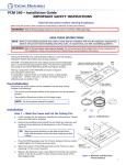
emove the cover to expose the inside of the switch. Using a
R
screwdriver, toggle the trip plate to force the electrical contacts
open and closed. The trip plate is silver, measures 13⁄4" x 1" and
is located towards the bottom of the switch. With the adjusting
pin located to the left, the normally closed contact will be closed
when the right hand side of the trip plate is depressed. Check
continuity at the terminal points COMMON and NORM CLOSED or
at the fan controller to confirm contacts are operational. A typical
control circuit uses a closed contact to allow the fan to run. An
open contact means excessive vibration has occurred shutting
off the starter or VFD.
The default trip setting should allow for a full voltage start and
operation at all speeds. If the trip point is too sensitive turn the
adjusting screw clockwise 1⁄8 of a turn increasing the g force trip
point and operate fan again. 1⁄8 of a turn equals 1g force in change
and the range is only 5gs on most switches so do not over-turn.
Do not turn the adjusting screw anymore than half of a full turn in
either direction from factory setting.
➠
3
Installation
Turning Adjustment Screw Too Far Counter-Clockwise
• If the adjusting screw is turned too far counter-clockwise (approximately
3-4 turns) the switch will trip and will not stay in a reset position after
depressing the manual reset pushbutton.
• At approximately 11 turns the switch will trip and cannot be reset because
the spring and adjusting rod have dislodged out of position. There is no
mechanical stop position when turning counter clockwise. Repair of the
internal mechanism can be accomplished in the field by removing the
internal switch mechanism from the switch body. The switch mechanism
is held in with three screws. Once removed the adjusting rod and spring
may be put back into operating position.
Turning Adjustment Screw Too Far Clockwise
• The adjusting rod has a nylon stop bushing preventing the rod from being over turned. Once the adjustment bottoms out, the switch is at or
beyond the maximum setting and may not trip on vibration.
Getting The Adjustment Position Back To Normal
• Once an adjustment screw is out of range and the rod and spring have
not been dislodged the switch may be adjusted back to normal settings.
With the switch cover removed rotate the adjusting rod clockwise until it
bottoms out. Push the right hand side of the trip plate down to reset the
switch. At this point the NORM CLOSED CONTACT is closed. Rotate the
adjusting rod approximately two turns counter-clockwise slowly or until
the trip bar moves up with a click. Then rotate the adjusting rod clockwise
one full turn. If tower start or run position trips the switch then rotate the
adjusting rod clockwise in 1⁄8 increments until the trip holds in.
4
Installation
Electrical Reset and Startup Lockout
The optional electrical reset circuit consists of an electrical solenoid in
series with a thermistor. If the rated voltage is continuously applied to the
reset circuit at machine startup, the reset solenoid energizes for a fixed
time interval (approximately 30 seconds), after which time the solenoid is
automatically de-energized by the thermistor. This action provides a trip
lockout during machine startup roughness. The voltage must be removed
from the reset circuit when the machine is stopped to allow the thermistor to cool off. The switch mechanism can then be reset electrically by a
momentary application of the reset voltage or it can be reset manually.
Note
If the machine is restarted immediately after a shutdown, the lockout
period will be shortened because the thermistor will be hot. An increase
in the ambient temperature will also shorten the lockout period.
Specifications
Function––Armature mechanism trips on high vibration and operates snap
action switch(es).
Amplitude Range––See How to Order ("C").
Frequency Range––0 to 3600 RPM.
Setpoint Adjust––0 to 100% of range. External setpoint adjustment.
Reset––Local reset, plus optional remote reset electrical coil. See How
to Order ("D").
Start Delay––Applying reset coil voltage at start up holds mechanism
from tripping for 20-30 seconds, after which the switch is active. Requires
electric reset option.
Temperature Range–– -40ºF to 160ºF
Enclosure––High strength copper-free (4⁄10 or 1% max) aluminum alloy.
Environmental Rating––NEMA 4, IP 65 & CE Mark (NEMA 4X Optional).
Switch Contact(s) Rating––15 amps, 125, or 480 VAC; 1⁄8 hp, 125 VAC;
1
⁄4 hp, 250 VAC; 1⁄2 amp, 125 VDC; 1⁄4 amp, 250 VDC.
Hazard Rating––See How to Order ("A").
Weight––4.0 lb
5
Installation
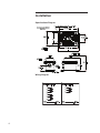
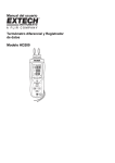
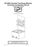
Specifications Diagram
* = SEE FOOT PRINT TABLE NEXT PAGE (E=1, 6 SHOWN)
4X 19.0mm X 9.5mm OBROUND
(.750 X .375)
A Mounting Holes*
Vibr A lert
480 VAC
-
Class I I , Div 1 , Groups
INCREASE
SETPOINT
LISTED
5550
341R
S/N
108mm [4.25]
W
*
, MAX . , 15A . / 250 VDC , MAX . , 1/4A .
/ 1/4 HP , 250 VAC
Class I , Div 1 , Groups
1/8 HP , 125 VAC
VIBRATION SWITCH
FOR USE IN HAZARDOUS LOCATIONS
MODEL 5550
B *
Mounting Holes
RESET COIL
@
MAX.
IP 65 ENCLOSURE TYPE 4
RANGE =
CAUTION
G 's
-
MAXIMUM AMBIENT
TEMP. RANGE
-40 C to 70 C
RESET
TO REDUCE THE RISK OF IGNITION OF HAZARDOUS ATMOSPHERES,
DISCONNECT THE DEVICE FROM THE SUPPLY CIRCUIT BEFORE OPENING.
KEEP ASSEMBLY TIGHTLY CLOSED WHEN IN OPERATION.
INSTRUMENT CO.
HOUSTON, TEXAS USA
142mm [5.60]
SETPOINT
ADJUSTMENT
*
L
PUSH-BUTTON RESET
3/4" NPT ENTRY
135mm [5.33]
113mm [4.43]
GROUND
CONNECTION
48mm [1.88]
MOUNTING PLATE
Wiring Diagram
DPDT CONTACTS
SPDT CONTACTS
1
1
2
2
3
4
3
5
6
GRN
6
CASE
GRN
CASE
Installation
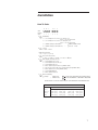
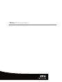
How To Order
B
A
C
Example:
5550A
D
E
F
0
2
0
-
55501
1
1
-
Hazard Rating
1=
UL, cUL Explosion Proof, Class I, Div 1, Groups C & D
Class II, Div 1, Groups E, F & G
UL, cUL Explosion Proof, Class I, Div 1, Groups B, C & D
Class II, Div 1, Groups E, F & G
2=
DEMKO 02 ATEX 0212409
3=
CENELEC Flameproof, EEx d IIB T6
4=
CENELEC Flameproof, EEx d IIB+H T6
B
Contacts
C
Full Scale Range
CE 0600
2
11 2 GD
1= SPDT 2= DPDT
1= 5 g 2= †2 g 3= 10 g
D
Reset Coil & Start Up Delay
E
Wiring Entry/Mounting Plate (retro fit)
0 = None 1 = 115 VAC 2 = 230 VAC 3 = 24 VDC 4 = 115 VDC
F
1=
3/4" NPT/Metrix 5173 or 5175
2=
3/4" NPT/Metrix 5097; VS-2-EX; 366
3=
3/4" NPT/Metrix 5078; 365
4=
M20 x 1.5/Metrix 5097; VS-2-EX; 366 (CENELEC ONLY)
5=
Same as option 4 above with epoxy coated mounting plate (CENELEC ONLY)
6=
M20 x 1.5/Metrix 5173 or 5175 (CENELEC ONLY)
7=
3/4" NPT/PMC/BETA 440
8=
M20 x 1.5/Metrix 5078; 365
Environmental Rating
NEMA 4, IP65,
0 (or blank) =
=
1
†
TESTED FOR COMPLIANCE WITH THE APPLICABLE
EC ELECTROMAGNETIC COMPATIBILITY REQUIREMENTS
NEMA 4X, IP65,
WHEN OPTION C=2, OPTION D CANNOT EQUAL 3 FOR OPERATION IN THE HORIZONTAL AXIS.
FOOT PRINT TABLE
L
W
A
E=1, 6
165mm [6.50]
83mm [3.25]
141mm [5.56]
59mm [2.33]
B
E=2, 4, 5
121mm [4.75]
152mm [6.00]
79mm [3.12]
118mm [4.63]
E=3, 8
165mm [6.50]
121mm [4.75]
136mm [5.37]
92mm [3.62]
E=7
114mm [4.50]
127mm [5.00]
71mm [2.80]
108mm [4.25]
7
7401 WEST 129 STREET | OVERLAND PARK, KANSAS 66213 UNITED STATES | 913 664 7400 | [email protected] | spxcooling.com
In the interest of technological progress, all products are subject to design and/or material change without notice.
©2008 SPX Cooling Technologies, Inc. | Printed in USA
M07-1274