1
U S E R M A N UA L
M-5 vibration switch
I N S TA L L AT I O N - O P E R AT I O N - M A I N T E N A N C E
M2010-1241
I SSU E D 04/2013
R EAD AN D U N D E R STAN D TH I S MAN UAL PR IOR TO OPE RATI NG OR S E RVICI NG TH I S PROD UCT.
installation
This bulletin should be used by experienced personnel as a guide to the installation of the Marley M-5 vibration switch. Selection or installation of equipment
should always be accompanied by competent technical assistance.
Caution
Before proceeding to install and wire the unit, read and thoroughly understand these instructions. The switch model number should be checked
to confirm that you have the correct hazardous area rating for your application.
Installation
1—The sensitive axis of the vibration switch is perpendicular to the mounting
base. The preferred mounting is with the sensitive axis in the horizontal
plane, since most machines vibrate more in that plane. Mount the switch
solidly to the frame of the machine. In most cases the switch or mounting
bracket will come preinstalled.
2—Remove the cover and wire the switch(es) into the alarm or shutdown circuit.
Do not exceed switch contact ratings listed in the specifications. Keep field
wiring away from the moving part of the mechanism.
3—Observe all local electrical codes.
4—All the power must be switched off before opening of the enclosure in an
explosive atmosphere.
5–The Vibration Switch must be electrically connected by means of a flameproof cable gland or stopping box certified to EN 50018.
6–For ambient temperatures below +14ºF and above +140ºF use field wiring
suitable for both minimum and maximum ambient temperature.
7–Reinstall the cover by first insuring the sealing gasket is in place and properly
seated in the grove in the housing. Place the cover on the unit and install
the four cover bolts. Torque the four bolts to 16 ft·lb. Caution should be
used to not over-torque the bolts as this could damage the housing and
compromise the seal.
8–The temporary conduit entry plugs are placed in the housing to provide
physical protection for the threads during shipping. Once the unit is installed
in the field these plugs must be replaced. These temporary plugs do not
provide adequate environmental protection for the switch when installed
in the field.
2
operation
Vibration Switch Testing
Warning
Caution
Note
The vibration switch is a safety circuit acting as a run permissive for the
VFD or starter controlling the fan motor. Follow lockout / tagout procedures
on the fan starting equipment.
A special tool is required to adjust the setpoint—do not attempt to adjust.
Adjusting the setpoint will VOID the warranty. The setpoint is factory set
at 1g which is more than sufficient to allow the mechanical equipment to
get up to speed without tripping the motor. The default trip setting should
allow for a full voltage start and operation at all speeds.
During installation and testing, if a problem with either the sensitizing
or desensitizing setting is suspected or you think the unit is defective,
do not attempt to adjust the setpoint. Call 800-462-7539 or 281-9401802 Field Service or 713-702-8805 Technical Assistance after hours for
troubleshooting.
To test the operation of the electrical contacts in the vibration switch please
follow one of the provided procedures below. The first test procedure is the
recommended procedure to use without having to remove the switch cover.
Test 1 – Do not adjust the setpoint. Loosen the four mounting bolts
on the vibration switch support—do not remove. Either lightly tap or
shake the vibration switch thus triggering the unit indicating the unit
is active. Retighten the mounting bolts and reset the unit.
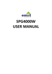
Test 2 – Do not adjust setpoint. Remove the cover to expose the
inside of the switch. Using a screwdriver, toggle the trip plate to force
the electrical contacts open and closed. The trip plate is bright metal
and measures 13⁄4" x 1" and is located towards the bottom of the
switch. With the adjusting pin located to the left, the normally closed
contact will be closed when the right hand side of the trip plate is
depressed. Check continuity at the terminal points COMMON and
NORM CLOSED or at the fan controller to confirm contacts are operational. A typical control circuit uses a closed contact to allow the
fan to run. An open contact means excessive vibration has occurred
shutting off the starter or VFD.
3
operation
Note
As stated previously, adjusting the setpoint will void the warranty on this
switch. If by either accident or intentionally, the setpoint is tampered with,
the following instructions are provided indicating how to properly readjust
the setpoint. If the proper setpoint cannot be achieved through these
steps, then call for technical assistance. In order to adjust the setpoint,
a special tool is required and may be furnished upon request from SPX
Cooling Technologies.
Turning Setpoint Adjustment Too Far Counter-Clockwise
• If the setpoint adjustment is turned too far counter-clockwise (approximately
3-4 turns) the switch will trip and will not stay in a reset position after depressing the manual reset push-button.
•A
t approximately 11 turns the switch will trip and cannot be reset because
the spring and adjusting rod have dislodged out of position. There is no
mechanical stop position when turning counter clockwise. Repair of the internal mechanism can be accomplished in the field by removing the internal
switch mechanism from the switch body. The switch mechanism is held in
with three screws. Once removed the adjusting rod and spring may be put
back into operating position.
Turning Setpoint Adjustment Too Far Clockwise
•T
he adjusting rod has a nylon stop bushing preventing the rod from being
over turned. Once the adjustment bottoms out, the switch is at or beyond
the maximum setting and may not trip on vibration.
Getting The Adjustment Position Back To Normal
•O
nce an adjustment is out of range and the rod and spring have not been
dislodged the switch may be adjusted back to normal settings. With the
switch cover removed rotate the adjusting rod clockwise until it bottoms
out. Push the right hand side of the trip plate down to reset the switch. At
this point the NORM CLOSED CONTACT is closed. Rotate the adjusting
rod approximately two turns counter-clockwise slowly or until the trip bar
moves up with a click. Then rotate the adjusting rod clockwise one full turn.
If the cooling product fan start or run position trips the switch then rotate the
adjusting rod clockwise in 1⁄8 increments until the trip holds in.
4
operaton – specifications
Electrical Reset and Startup Lockout
The optional electrical reset circuit consists of an electrical solenoid in series
with a thermistor. If the rated voltage is continuously applied to the reset circuit
at startup, the reset solenoid energizes for a fixed time interval (approximately
30 seconds), after which time the solenoid is automatically de-energized by
the thermistor. This action provides a trip lockout during machine startup
roughness. The voltage must be removed from the reset circuit when the fan
motor is stopped to allow the thermistor to cool off. The switch mechanism
can then be reset electrically by a momentary application of the reset voltage
or it can be reset manually.
Note
If the fan motor is restarted immediately after a shutdown, the lockout
period will be shortened because the thermistor will be hot. An increase
in the ambient temperature will also shorten the lockout period.
Specifications
Function—Armature mechanism trips on high vibration and operates snap
action switch(es).
Frequency Range—0 to 3600 RPM.
Reset—Local reset, plus optional remote reset electrical coil. See How to
Order ("D").
Start Delay—Applying reset coil voltage at start up holds mechanism from
tripping for 20-30 seconds, after which the switch is active. Requires electric
reset option.
Temperature Range— -40ºF to 160ºF
Enclosure—High strength copper-free (4⁄10 of 1% max) aluminum alloy.
Environmental Rating—NEMA 4, IP 65 & CE Mark (NEMA 4X Optional).
Switch Contact(s) Rating—15 amps, 125, or 480 VAC; 1⁄8 hp, 125 VAC; 1⁄4
hp, 250 VAC; 1⁄2 amp, 125 VDC; 1⁄4 amp, 250 VDC.
Hazard Rating—See How to Order ("A").
Weight—4.0 lb
5
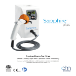
dimensions – wiring
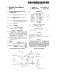
Schematic
.75" x .375 Holes (4)
4.25"
5.56" Mounting Holes
2.33"
Mounting Holes
3.25"
5.60"
6.50"
Push-Button Reset
Ground
Connection
.75" NPT Entry
5.33"
4.43"
1.88"
Mounting Plate
Wiring
Dependent on switch configuration
DPDT Contacts
1
2
3
4
5
6
L (+) 7 Reset Coil
N (–) 8 Reset Coil
GRN
Case
DPDT Contacts
1
2
3
4
5
6
6
SPDT Contacts
1
2
3
L (+) 4 Reset Coil
N (–) 5 Reset Coil
GRN
Case
SPDT Contacts
1
2
3
replacement
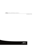
How To Order
For new or replacement vibration switches call 1-800-4Marley
A
M-5
B
C
D
E
F
ooo-ooo
Example: M-5 111-010
A
o
Hazard Rating
0 = None
1 = UL, cUL Explosion Proof, Class I, Div 1, Groups C and D
Class II, Div 1, Groups E, F and G
2 = UL, cUL Explosion Proof, Class I, Div 1, Groups B, C and D
B
o
Contacts
1 = SPDT 2 = DPDT
C
Class II, Div 1, Groups E, F and G
o
Full Scale Range
1 = 5g 2 = 2g 3 = 10g
D
o Reset Coil and Startup Delay
0 = None 1 = 115VAC 2 = 230VAC 3 = 24VDC 4 = 115VDC
E
o
1 = 3⁄4" NPT 6 = M20 x 1.5
F
Wiring Entry/Mounting Plate (retro fit)
o
Environmental Rating
0 (or blank) = NEMA 4, IP65 1 = NEMA 4X, IP65
Tested for compliance with the applicable EC Electromagnetic Compatibility requirements
note When Option C = 2, Option D cannot = 3 for operation in the
horizontal axis.
When Option A = 1 or A = 2, Option E cannot = 6
7
M-5 vibraton switch
user manual
Note
This electronic equipment was manufactured according to high quality standards to ensure safe and reliable operation when used as intended. Due to its
nature, this equipment may contain small quantities of substances known to be
hazardous to the environment or to human health if released into the environment. For this reason, Waste Electrical and Electronic Equipment (commonly
known as WEEE) should never be disposed of in the public waste stream.
The “Crossed-Out Waste Bin” label affixed to this product is a reminder to
dispose of this product in accordance with local WEEE regulations. If you
have questions about the disposal process, please contact SPX Cooling
Technologies customer service.
S PX C O O L I N G T E C H N O LO G I E S , I N C .
7401 W 129 STREET
OVERLAND PARK, KANSAS 66213 USA
P: 913 664 7400
F: 913 664 7439
[email protected]
In the interest of technological progress, all products are subject to design
and/or material change without notice
ISSUED 04/2013 M2010-1241
COPYRIGHT ©2013 SPX Corporation