1
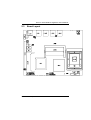
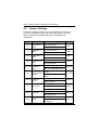
NA-811 Series Desktop Network Appliance User’s Manual Disclaimers This manual has been carefully checked and believed to contain accurate information. AXIOMTEK Co., Ltd. assumes no responsibility for any infringements of patents or any third party’s rights, and any liability arising from such use. AXIOMTEK does not warrant or assume any legal liability or responsibility for the accuracy, completeness or usefulness of any information in this document. AXIOMTEK does not make any commitment to update the information in this manual. AXIOMTEK reserves the right to change or revise this document and/or product at any time without notice. No part of this document may be reproduced, stored in a retrieval system, or transmitted, in any form or by any means, electronic, mechanical, photocopying, recording, or otherwise, without the prior written permission of AXIOMTEK Co., Ltd. ©Copyright 2008 AXIOMTEK Co., Ltd. All Rights Reserved March 2008, Version A2 Printed in Taiwan ii Safety Approvals CE Marking FCC Class B FCC Compliance This equipment has been tested and complies with the limits for a Class B digital device, pursuant to Part 15 of the FCC Rules. These limits are designed to provide reasonable protection against harmful interference in a residential installation. If not installed and used in accordance with proper instructions, this equipment might generate or radiate radio frequency energy and cause harmful interference to radio communications. However, there is no guarantee that interference will not occur in a particular installation. If this equipment does cause harmful interference to radio or television reception, which can be determined by turning the equipment off and on, the user is encouraged to try to correct the interference by one or more of the following measurers: Reorient or relocate the receiving antenna. Increase the separation between the equipment and receiver. Connect the equipment into an outlet on a circuit different from that to which the receiver is connected. Consult the dealer or an experienced radio/TV technician for help. Shielded interface cables must be used in order to comply with emission limits. iii Safety Precautions Before getting started, read the following important cautions. 1. Be sure to ground yourself to prevent static charge when installing the internal components. Use a grounding wrist strap and place all electronic components in any static-shielded devices. Most electronic components are sensitive to static electrical charge. 2. Disconnect the power cords from the NA-811 Series before making any installation. Be sure both the system and the external devices are turned OFF. Sudden surge of power could ruin sensitive components. Make sure the NA-811 Series is properly grounded. 3. Do not open the system’s top cover. If opening the cover for maintenance is a must, only a trained technician is allowed to do so. Integrated circuits on computer boards are sensitive to static electricity. To avoid damaging chips from electrostatic discharge, observe the following precautions: ¾ Before handling a board or integrated circuit, touch an unpainted portion of the system unit chassis for a few seconds. This will help to discharge any static electricity on your body. ¾ When handling boards and components, wear a wristgrounding strap, available from most electronic component stores. Trademarks Acknowledgments AXIOMTEK is a trademark of AXIOMTEK Co., Ltd. IBM, PC/AT, PS/2, VGA are trademarks of International Business Machines Corporation. ® ® Intel and Pentium are registered trademarks of Intel Corporation. MS-DOS, Microsoft C and QuickBASIC are trademarks of Microsoft Corporation. Other brand names and trademarks are the properties and registered brands of their respective owners. iv Table of Contents Disclaimers ........................................................................................................... ii Safety Approvals ................................................................................................. iii Safety Precautions ...............................................................................................iv Chapter 1 Introduction .................................................................... 1 1.1 1.2 1.3 General Description................................................................................. 1 Features .................................................................................................. 2 Specifications .......................................................................................... 3 1.3.1 System ............................................................................................. 3 1.3.2 Mechanical / Environmental ............................................................ 3 1.4 Dimensions and Outlines ........................................................................ 5 1.5 I/O Outlets ............................................................................................... 6 1.5.1 Front Panel...................................................................................... 6 1.5.2 Rear Panel ...................................................................................... 8 Chapter 2 Hardware Description.................................................... 9 2.1 2.2 2.3 2.4 Checklist.................................................................................................. 9 Memory Module (SODIMM)................................................................... 10 Board Layout ......................................................................................... 11 Jumper Settings .................................................................................... 12 2.4.1 LAN1 Enable or Disable Jumper (JP1) ......................................... 14 2.4.2 LAN2 Enable or Disable Jumper (JP2) ......................................... 14 2.4.3 LAN3 Enable or Disable Jumper (JP8) ......................................... 15 2.4.4 LAN4 Enable or Disable Jumper (JP9) ......................................... 15 2.4.5 Software Program LAN Bypass Jumper (JP3, JP4)...................... 16 2.4.6 LAN Bypass Mode Selection Jumper (JP5) .................................. 16 2.4.7 CF IDE Bus Selection Jumper (JP14) ........................................... 17 2.4.8 FSB Selection Jumper (JP17) ....................................................... 17 2.4.9 CompactFlash Voltage Jumper (JP19) ......................................... 18 2.4.10 Watchdog Control Options Jumper (JP21)................................... 18 2.4.11 CMOS Clear Jumper (JP23) ........................................................ 19 2.4.12 VGA Enable or Disable Jumper (JP24)........................................ 19 2.4.13 PCI Slot Support PICMG or PCI Device Jumpers........................ 20 2.5 Connectors ............................................................................................ 21 2.5.1 Keyboard & PS/2 Mouse Connector (CN6)................................... 22 2.5.2 SATA Connector 1 (CN7) & SATA Connector 2 (CN9)................. 22 2.5.3 FAN1 Connector (CN13) & FAN2 Connector (CN16) ................... 23 2.5.4 VGA Connector (CN15)................................................................. 23 TM 2.5.5 CompactFlash Connector (SCN1) ............................................. 24 Chapter 3 Award BIOS Utility ....................................................... 26 3.1 3.2 3.3 3.4 Entering Setup....................................................................................... 26 Control Keys .......................................................................................... 27 Getting Help .......................................................................................... 27 The Main Menu ..................................................................................... 28 v 3.5 3.6 3.7 3.8 3.9 3.10 3.11 3.12 3.13 3.14 3.15 3.16 3.17 Standard CMOS Setup Menu................................................................ 29 Advanced BIOS Features...................................................................... 31 Advanced Chipset Features .................................................................. 36 Integrated Peripherals ........................................................................... 37 Power Management Setup .................................................................... 42 PnP/PCI Configuration Setup................................................................ 45 PC Health Status................................................................................... 47 Frequency/Voltage Control.................................................................... 48 Load Fail-Safe Defaults......................................................................... 49 Load Optimized Defaults ....................................................................... 50 Set Supervisor/User Password ............................................................. 51 Save & Exit Setup ................................................................................. 52 Exit Without Saving ............................................................................... 53 Appendix Enabling LAN Bypass Features................................ 54 vi NA-811 Series Network Appliance User’s Manual Chapter 1 Introduction This chapter contains general information and detailed specifications of the NA-811 Series Network Appliance Server. Chapter 1 contains the following sections: 1.1 General Description Features Specifications Dimensions I/O Outlets General Description The NA-811 Series server is a 1U and desktop network security hardware platform for VPN, firewall and other network security applications like UTM. It is particularly designed with fanless form factor for network software solution providers that they can achieve data security, voice over IP, video streaming, network bandwidth controller and meet other networking appliance requirements for stable and reliable multiple LAN devices. It can be extended up to four LAN ports that customers can easily combine any components to make the best application as they want. ® ® The NA-811 can support ULV Intel Celeron M 1GHz w/zero L2 ® cache or Pentium M socket, and provide two SODIMM slots for DDR2 system maximum memory up to 2GB. In the meantime, this network platform supports PCIe interface Gigabit LAN ports to deal with an excellent throughput of data. For storing event log data purpose, the NA-811 Series features one builtin 2.5” S-ATA Hard Disk to perform the function of system log and Introduction 1 NA-811 Series Network Appliance User’s Manual monitoring. Furthermore, this 1U unit also offers LAN by-pass function controlled through WDT and GPIO pin definition without interruption that can prevent defective segments from the server. With its innovative mechanical and electrical design, the NA-811 Series provides you with one mini-PCI expansion slot for VPN encryption / decryption adapter board and another type of Mini-PCI adapter card enabling. It can enhance network security processing and reduce the CPU loading. It is also an excellent networking application platform for network secure in the SOHO (Small Office and Home Office) business. 1.2 Features Low power and high performance ULV Intel z ® ® ® Celeron M 1GHz w/ zero cache processor or Pentium M CPU Supports four 10/100/1000Mbps Ethernet Supports BIOS redirected to COM port features Supports single S-ATA 2.5” Hard Disk for event log or proxy data High computing performance and throughput for processor and LAN ports Suitable for network appliance; VPN, network bandwidth controller, firewall and UTM z z z z z 2 Introduction NA-811 Series Network Appliance User’s Manual 1.3 Specifications 1.3.1 z z z System CPU ® ® ULV Intel Celeron M 1 GHz and zero L2 cache processor (NA-811A) Intel Pentium M CPU socket (NA-811B) ® ® System Chipset ® Intel 910GMLE + ICH6-M (NA-811A) Intel 915GME + ICH6-M (NA-811B) ® BIOS z System Award 4Mbit PnP Flash BIOS with function of BIOS redirected to COM port System Memory Up to 2 GB for DDRII 400/533 SODIMM 1.3.2 Mechanical / Environmental z S-ATA Interface Single 2.5” S ATA HDD z Network Interface (PCIe transaction bus) ® Four RJ-45 10/100/1000Mbps (Intel 82573) ports z Watchdog Timer 255 stepping for porting z USB Two USB ports in the front, others are pin header internally z Other Features (optional) LAN by-pass function through WDT and GPIO pin control z Power One 12V, 5A power adapter Introduction 3 NA-811 Series Network Appliance User’s Manual OS Compatibility Redhat Linux 2.4 and 2.6 Kernel z NOTE All specifications and images are subject to change without notice. 4 Introduction NA-811 Series Network Appliance User’s Manual 1.4 Dimensions and Outlines The following diagrams show you dimensions and outlines of the NA811 Series. Introduction 5 NA-811 Series Network Appliance User’s Manual 1.5 I/O Outlets Locate front and rear panel I/O outlets on the NA-811 Series server to connect serial and Ethernet interface devices. 1.5.1 Front Panel LAN link/transfer rate 6 Console Port z Console port It is a DB-9 RS-232 Console port for command line interface and diagnostic support by P.O.S.T (Power On Self Test). z Power It will be lighting when the server is powered on to perform diagnostic tests and check a proper operation. z LAN Link It will be lighting when a Twisted pair is connected to another Ethernet device on the port. z Transfer Rate It shows network transfer rate while making a connection. z Activity It will be lighting when the server is transmitting or receiving a packet through the twisted pair ports. Introduction NA-811 Series Network Appliance User’s Manual z Power on LED System and power on z HDD LED Link/Active LED (single color) 1. The green LED is on when it is a normal HD connection. 2. The LED flashes when transmitting or receiving any signals. z Link/Active LED (Single color)for LAN port #1, port#2, port#3 and port#4 1. The yellow LED is on when the LAN port connection is working. 2. The LED flashes when transmitting or receiving any signals to or from the appliance. 3. The LED is dark when the appliance is off. z Transmitted LED for LAN port #1, port#2, port#3 and port#4 1. The green-color LED light indicates 10/100Mbps transfer rate. 2. When the orange-color LED light is radiating, it should be 1000Mbps transfer rate at this moment. 3. The LED will be dark when the Link/Active LED is dark, too. No networking devices are attached. Introduction 7 NA-811 Series Network Appliance User’s Manual 1.5.2 Rear Panel 12V/5A DC Power Input 8 LAN Ports USB Ports Introduction NA-811 Series Network Appliance User’s Manual Chapter 2 Hardware Description The NA-811 Series are convenient for your various hardware configurations. The chapter 2 will help you get familiar with the hardware. 2.1 Checklist The package bundled with your NA-811 Series should contain the following items: z The NA-811 series network appliance hardware platform z Power cord x 1 Utility CD (including this User’s Manual) Mounting screws for disk drive and additional screws for this appliance’s spareparts Installed NA-811 cable kits (1 x S-ATA cable, 1 x S-ATA power cable) Optional cable kits (1 x console cable, 1 x PS/2 keyboard and mouse cable, 1 x VGA cable) Plastic stand for stack–up x 4 z z z z z If you can not find this package or any items are missing, please contact AXIOMTEK distributors immediately. If you order any optional components, the package might contain those additional hardware or documents accordingly. Hardware Description 9 NA-811 Series Network Appliance User’s Manual 2.2 Memory Module (SODIMM) The main board supports one SODIMM socket with maximum memory capacity up to 2GB None-ECC unbuffer memory. The following steps show you how to install the memory modules: 1 2 Push down each side of the SODIMM socket. Align the memory module with the socket that notches of memory module must match the socket keys for a correct intallation. Install the memory module into the socket and push it firmly down until it is fully seated. The socket latches are levered upwards and clipped on to the edges of the DIMM. Install any remaining SODIMM modules. 3 4 Notice 1 When you are handling electrostatic discharge-sensitive (ESDs), please take precautions to avoid any damage from static electricity. Notice 2 The memory can support DDRII 400/533. 10 Hardware Description NA-811 Series Network Appliance User’s Manual 2.3 Board Layout Hardware Description 11 NA-811 Series Network Appliance User’s Manual 2.4 Jumper Settings Proper jumer settings configure the main board in this applicance to meet your application purpose. We are herewith listing a summary table of all jumpers and default settings for onboard devices, respectively. Jumper JP1 JP2 JP8 JP9 Function LAN1 Enable or Disable LAN2 Enable or Disable LAN3 Enable or Disable LAN4 Enable or Disable Jumper Settings Default Short:LAN1 Disable Open Open:LAN1 Enable Short:LAN2 Disable Open Open:LAN2 Enable Short:LAN3 Disable Open Open:LAN3 Enable Short:LAN4 Disable Open Open:LAN4 Enable Software Program Short JP3: Default Low GPIO JP3, JP4 LAN bypass Short JP4: Default High GPIO Function Short JP4 JP5 Short:(1-2) LAN Bypass always LAN Bypass Mode disable Not Install Selection Short:(2-3) LAN Bypass always Enable JP14 CF IDE bus selection Short:(2-3) Master Short:(2-3) Short:(1-2) Slave Short:(1-3)(2-4)Auto JP17 FSB selection Short:(3-5) Short:(3-5)100MHz Short:(3-5)(4-6)133MHz JP19 CF Voltage Short:(1-2) CF 3.3V Short:(1-2) Short:(2-3) CF 5V JP21 12 Short:(1-2) System Reset Watchdog Control Short:(2-3) Watchdog control Options LAN Bypass Short:(2-3) Hardware Description NA-811 Series Network Appliance User’s Manual Jumper JP23 Function Clear COMS Jumper Settings Short:(1-2) Normal Default Short:(1-2) Short:(2-3) Clear JP24 VGA Enable or Disable JP10 JP11 JP16 JP18 PCI Slot support PICMG or PCI device JP22 Short: VGA Disable Open Open:VGA Enable PICMG: Short JP10(2-3), JP11(2-3), JP16(1-2), JP18(23), JP22(1-2) PICMG PCI: Short JP10(1-2), JP11(12), JP18(1-2); Open JP16, JP22 Note The jupmper JP5 won’t be installed as a default on the board. It will be set upon the request from OEM / ODM customers. Hardware Description 13 NA-811 Series Network Appliance User’s Manual 2.4.1 LAN1 Enable or Disable Jumper (JP1) Use this jumper to enable or disable the LAN1 function. Description LAN1 Enable or Disable 2.4.2 Function Jumper Setting Disable JP1 Enable (Default) JP1 LAN2 Enable or Disable Jumper (JP2) Use this jumper to enable or disable the LAN2 function. Description LAN2 Enable or Disable 14 Function Jumper Setting Disable JP2 Enable (Default) JP2 Hardware Description NA-811 Series Network Appliance User’s Manual 2.4.3 LAN3 Enable or Disable Jumper (JP8) Use this jumper to enable or disable the LAN3 function. Description LAN3 Enable or Disable 2.4.4 Function Jumper Setting Disable JP8 Enable (Default) JP8 LAN4 Enable or Disable Jumper (JP9) Use this jumper to enable or disable the LAN4 function. Description LAN4 Enable or Disable Hardware Description Function Jumper Setting Disable JP9 Enable (Default) JP9 15 NA-811 Series Network Appliance User’s Manual 2.4.5 Software Program LAN Bypass Jumper (JP3, JP4) Description Function Software Program Low Level LAN Bypass GPIO Function High Level GPIO (Default) Jumper Setting JP3 JP4 JP3 JP4 Note If the jumper setting is “Low Level GPIO”, LAN Bypass function will stil be started even when power supply is normally input. The default setting is “High Level GPIO” that LAN Bypass function is not working when power supply is normally input. 2.4.6 LAN Bypass Mode Selection Jumper (JP5) Use this jumper to select the LAN Bypass Mode. Description Function Jumper Setting LAN Bypass Mode LAN Bypass Selection always disable JP5 LAN Bypass always enable JP5 Note This jumber will not be produced in default, it is for engineer test or customized requirement only. 16 Hardware Description NA-811 Series Network Appliance User’s Manual 2.4.7 CF IDE Bus Selection Jumper (JP14) This jumper is to select the IDE Bus for CompactFlash interface. Description CF IDE Bus Selection 2.4.8 Function Jumper Setting Master (Default) JP14 Slave JP14 FSB Selection Jumper (JP17) Use this jumper to select the Front Side Bus speed. Description Function CPU Clock Select Auto Hardware Description Jumper Setting JP17 100 MHz (Default) JP17 133 MHz JP17 17 NA-811 Series Network Appliance User’s Manual 2.4.9 CompactFlash Voltage Jumper (JP19) This jumper is to select the voltage for CompactFlash interface. Description CF Voltage Function Jumper Setting 3.3V (Default) JP19 5V JP19 2.4.10 Watchdog Control Options Jumper (JP21) The board features a special watchdog timer that can perform the sensitive error detection and report function. Description Watchdog Control Options 18 Function Jumper Setting System Reset JP21 Watchdog Control LAN Bypass (Default) JP21 Hardware Description NA-811 Series Network Appliance User’s Manual 2.4.11 CMOS Clear Jumper (JP23) You may need to use this jumper is to clear the CMOS memory if incorrect settings in the Setup Utility. Description CMOS Clear Function Jumper Setting Normal (Default) JP23 Clear CMOS JP23 2.4.12 VGA Enable or Disable Jumper (JP24) This jumper is to enable or disable VGA function. Description Function VGA Enable or Disable VGA Disable JP24 VGA Enable (Default) JP24 Hardware Description Jumper Setting 19 NA-811 Series Network Appliance User’s Manual 2.4.13 PCI Slot Support PICMG or PCI Device Jumpers (JP10, JP11, JP16, JP18, JP22) Jumper Description Jumper Setting Description JP10, JP11, JP18 PCI Slot Support Jumper PCI Slot Support 20 JP10, JP11, JP18 PICMG device (Default) PCI device Description Jumper Setting JP16, JP22 PCI device Jumper Setting Description PICMG device (Default) Jumper Setting JP16, JP22 Hardware Description NA-811 Series Network Appliance User’s Manual 2.5 Connectors Connectors connect the CPU card with other parts of the system. Loose or improper connection might cause problems. Make sure all connectors are properly and firmly connected. Label CN2 CN4 CN6 CN7 CN8 CN9 CN10 CN12 CN13 CN14 CN15 CN16 CN17 SCN1 Hardware Description Connector Power Connector SATA Power Connector KB/MS Connector SATA Connector 1 DDR2 SODIMM Memory Socket SATA Connectort 2 DDR2 SODIMM Memory Socket Mini PCI Slot FAN1 Connector Internal COM1 VGA Connector FAN2 Connector External COM1 Connector CompactFlash Socket 21 NA-811 Series Network Appliance User’s Manual 2.5.1 Keyboard & PS/2 Mouse Connector (CN6) The board supports a keyboard and Mouse interface. Connector CN6 is a DIN connector for PS/2 keyboard Connection VIA “Y” Cable. Pin Signal Pin Signal CN6 1 VCC 6 VCC 2 KBDATA 7 MSDATA 3 KBCLK 8 MSCLK 4 GND 9 GND 5 VCC 10 NC 2.5.2 SATA Connector 1 (CN7) & SATA Connector 2 (CN9) These SATA connectors are for high-speed SATA interface ports and they can be connected to serial ATA hard disk devices. Pin Signal Pin Signal 1 GND 2 TX+ 3 TX- 4 GND 5 RX- 6 RX+ 7 GND CN7, CN9 22 Hardware Description NA-811 Series Network Appliance User’s Manual 2.5.3 FAN1 Connector (CN13) & FAN2 Connector (CN16) You can connect the system cooling fan cable to FAN1/FAN2 for system cooling fan power. Pin 2.5.4 Signal CN13, CN16 1 Ground 2 +12V 3 Rotation Detection VGA Connector (CN15) The VGA connector CN15 on the board is a 16-pin connector. Pin Signal Pin 2 Signal 1 Red GND 3 Green 4 NC 5 Blue 6 GND 7 NC 8 DDC DAT 9 GND 10 GND 11 GND 12 Horizontal Sync 13 GND+ 14 Vertical Sync 15 DDC CLK 16 NC CN15 1 Hardware Description 2 3 4 5 6 7 9 8 10 11 13 15 12 14 16 23 NA-811 Series Network Appliance User’s Manual 2.5.5 CompactFlash TM Connector (SCN1) TM The board is equipped with a CompactFlash disk type-II socket on TM the solder side to support an IDE interface CompactFlash disk card with DMA mode supported. The socket is especially designed to avoid TM incorrect installation of the CompactFlash disk card. When installing TM or removing the CompactFlash disk card, please make sure the system power is off. Pin 1 3 5 7 9 11 13 15 17 19 21 23 25 27 29 31 33 35 37 39 41 43 45 47 49 24 Signal GND Data 4 Data 6 CS1# GND GND VCC GND GND Address 1 Data 0 Data 2 GND Data 11 Data 13 Data 15 GND IOWR# INTR CSEL# RESET# DMAREQ LED# Data 8 Data 10 Pin 2 4 6 8 10 12 14 16 18 20 22 24 26 28 30 32 34 36 38 40 42 44 46 48 50 Signal Data 3 Data 5 Data 7 GND GND GND GND GND Address 2 Address 0 Data 1 NC GND Data 12 Data 14 CS3# IORD# VCC VCC GND IORDY# DMAACKPATADET Data 9 GND Hardware Description NA-811 Series Network Appliance User’s Manual SCN1 Hardware Description 25 NA-811 Series Network Appliance User’s Manual Chapter 3 Award BIOS Utility The Phoenix-Award BIOS provides users with a built-in Setup program to modify basic system configuration. All configured parameters are stored in a battery-backed-up RAM (CMOS RAM) to save the Setup information whenever the power is turned off. 3.1 Entering Setup There are two ways to enter the Setup program. You may either turn ON the computer and press <Del> immediately, or press the <Del> and/or <Ctrl>, <Alt>, and <Esc> keys simultaneously when the following message appears at the bottom of the screen during POST (Power on Self Test). TO ENTER SETUP PRESS DEL KEY If the message disappears before you respond and you still want to enter Setup, please restart the system to try it again. Turning the system power OFF and ON, pressing the “RESET” button on the system case or simultaneously pressing <Ctrl>, <Alt>, and <Del> keys can restart the system. If you do not press keys at the right time and the system doesn’t boot, an error message will pop out to prompt you the following information: PRESS <F1> TO CONTINUE, <CTRL-ALT-ESC> OR <DEL> TO ENTER SETUP 26 Award BIOS Utility NA-811 Series Network Appliance User’s Manual 3.2 Control Keys Up arrow Move cursor to the previous item Down arrow Move cursor to the next item Left arrow Right arrow Move cursor to the item on the left hand Move to the item in the right hand Esc key Main Menu -- Quit and delete changes into CMOS Status Page Setup Menu and Option Page Setup Menu -- Exit current page and return to Main Menu Increase the numeric value or make changes PgUp/“+” key PgDn/“−“ key Decrease the numeric value or make changes F3 key General help, only for Status Page Setup Menu and Option Page Setup Menu Change color from total 16 colors. F2 to select color forward, (Shift) F2 to select color backward Reserved F4 key Reserved F1 key (Shift) F2 key F8 key Restore the previous CMOS value from CMOS, only for Option Page Setup Menu Load the default CMOS value from BIOS default table, only for Option Page Setup Menu Load the Setup default, only for Option Page Setup Menu Reserved F9 key Reserved F10 key Save all the CMOS changes, only for Main Menu F5 key F6 key F7 key 3.3 Getting Help z Main Menu The online description of the highlighted setup function is displayed at the bottom of the screen. z Status Page Setup Menu/Option Page Setup Menu Press <F1> to pop out a small Help window that provides the description of using appropriate keys and possible selections for highlighted items. Press <F1> or <Esc> to exit the Help Window. Award BIOS Utility 27 NA-811 Series Network Appliance User’s Manual 3.4 The Main Menu Once you enter the Award BIOS CMOS Setup Utility, the Main Menu appears on the screen. In the Main Menu, there are several Setup functions and a couple of Exit options for your selection. Use arrow keys to select the Setup Page you intend to configure then press <Enter> to accept or enter its sub-menu. NOTE If your computer can not boot after making and saving system changes with Setup, the Award BIOS will reset your system to the CMOS default settings via its built-in override feature. It is strongly recommended that you should avoid changing the chipset’s defaults. Both Award and your system manufacturer have carefully set up these defaults that provide the best performance and reliability. 28 Award BIOS Utility NA-811 Series Network Appliance User’s Manual 3.5 Standard CMOS Setup Menu The Standard CMOS Setup Menu displays basic information about your system. Use arrow keys to highlight each item, and use <PgUp> or <PgDn> key to select the value you want in each item. z Date The date format is <day>, <date> <month> <year>. Press <F3> to show the calendar. day date month year z It is determined by the BIOS and read only, from Sunday to Saturday. It can be keyed with the numerical/ function key, from 1 to 31. It is from January to December. It shows the current year of BIOS. Time This item shows current time of your system with the format <hour> <minute> <second>. The time is calculated based on the 24-hour military-time clock. For example, 1 p.m. is 13:00:00. Award BIOS Utility 29 NA-811 Series Network Appliance User’s Manual z IDE Channel Master/IDE Channel Slave These items identify the types of each IDE channel installed in the computer. There are 45 predefined types (Type 1 to Type 45) and 2 user’s definable types (Type User) for Enhanced IDE BIOS. Press <PgUp>/<+> or <PgDn>/<−> to select a numbered hard disk type, or directly type the number and press <Enter>. Please be noted your drive’s specifications must match the drive table. The hard disk will not work properly if you enter improper information. If your hard disk drive type does not match or is not listed, you can use Type User to manually define your own drive type. If selecting Type User, you will be asked to enter related information in the following items. Directly key in the information and press <Enter>. This information should be provided in the documentation from your hard disk vendor or the system manufacturer. If the HDD interface controller supports ESDI, select “Type 1”. If the HDD interface controller supports SCSI, select “None”. If the HDD interface controller supports CD-ROM, select “None”. CYLS. HEADS PRECOMP number of cylinders LANDZONE number of heads SECTORS write precom MODE landing zone number of sectors HDD access mode If there is no hard disk drive installed, select NONE and press <Enter>. Press <Esc> to return to the Main Menu page. 30 Award BIOS Utility NA-811 Series Network Appliance User’s Manual 3.6 Advanced BIOS Features This section allows you to configure and improve your system, to set up some system features according to your preference. Award BIOS Utility 31 NA-811 Series Network Appliance User’s Manual z CPU Feature Scroll to this item and press <Enter> to view the CPU Feature sub menu. z Hard Disk Boot Priority Scroll to this item and press <Enter> to view the sub menu to decide the disk boot priority. Press <Esc> to return to the Advanced BIOS Features page. 32 Award BIOS Utility NA-811 Series Network Appliance User’s Manual z Virus Warning This option flashes on the screen. During and after the system boot up, any attempt to write to the boot sector or partition table of the hard disk drive will halt the system with the following message. You can run an anti-virus program to locate the problem. The default setting is “Disabled”. ! WARNING ! Disk boot sector is to be modified Type “Y” to accept write or “N” to abort write Award Software, Inc. Enabled Disabled It automatically activates while the system boots up and a warning message appears for an attempt to access the boot sector or hard disk partition table. No warning message will appear for attempts to access the boot sector or hard disk partition table. NOTE This function is only available with DOS and other operating systems that do not trap INT13. z CPU L1 & L2 Cache These two options speed up memory access. However, it depends on the CPU/chipset design. The default setting is “Enabled”. CPUs without built-in internal cache will not provide the “CPU Internal Cache” item on the menu. Enabled Disabled Enable cache Disable cache z Hyper-Threading Technology Use this item to enable or disable Hyper-Threading Technology, which makes a single physical processor perform multi-tasking function as two logical ones. z Quick Power On Self Test This option speeds up Power on Self Test (POST) after you turn on the system power. If set as Enabled, BIOS will shorten or skip some check items during POST. The default setting is “Enabled”. Award BIOS Utility 33 NA-811 Series Network Appliance User’s Manual Enabled Disabled Enable Quick POST Normal POST z First/Second/Third Boot Device These items let you select the 1st, 2nd, and 3rd devices that the system will search for during its boot-up sequence. The wide range of selection includes Floppy, LS120, Hard Disk, CDROM, ZIP100, USB-FDD, USB-ZIP, USB-CDROM, LAN and Disabled. z Boot Other Device This item allows users to enable or disable the boot device not listed in the First/Second/Third boot devices option above. The default setting is “Enabled”. z Boot Up NumLock Status Set the the Num Lock status when the system is powered on. The default value is “On”. z Security Option This item allows you to limit access to the system and Setup, or just to Setup. The default value is “Setup”. System Setup If a wrong password is entered at the prompt, the system will not boot, the access to Setup will be denied, either. If a wrong password is entered at the prompt, the system will boot, but the access to Setup will be denied. NOTE To disable the security, select PASSWORD SETTING at Main Menu and then you will be asked to enter a password. Do not type anything, just press <Enter> and it will disable the security. Once the security is disabled, the system will boot and you can enter Setup freely. z APIC Mode Use this item to enable or disable APIC (Advanced Programmable Interrupt Controller) mode that provides symmetric multi-processing (SMP) for systems. z MPS Version Control For OS This item specifies the version of the Multiprocessor Specification (MPS). Version 1.4 has extended configuration tables to improve support for multiple PCI bus configurations and provide future expandability. 34 Award BIOS Utility NA-811 Series Network Appliance User’s Manual z OS Select for DRAM >64MB This item allows you to access the memory over 64MB in OS/2. z Console Redirection This item allows you to enable or disable the BIOS boot up and redirect to console port feature. Available options are “Enable” and “Disable”. z Baud Rate This item allows you to setup the data transfer rate for the console port. The default value is 9600. Available options are “9600”, “19200”, “38400”, “57600” and “115200”. z Agent after boot This item allows you to enable or disable the agent after boot. Available options are “Enable” and “Disable”. Press <Esc> to return to the Main Menu page. Award BIOS Utility 35 NA-811 Series Network Appliance User’s Manual 3.7 Advanced Chipset Features Since the features in this section are related to the chipset on the CPU board and are completely optimized, you are not recommended to change the default settings in this setup table unless you are well oriented with the chipset features. z PCI Express Root Port Func Scroll to this item and press <Enter> to view the sub menu to decide the PCI Express Port. Press <Esc> to return to the Advanced Chipset Featurs page, and press it again, return to the Main Menu page. 36 Award BIOS Utility NA-811 Series Network Appliance User’s Manual *** VGA Setting *** z On-Chip Frame Buffer Size Use this item to set the VGA frame buffer size. Press <Esc> to return to the Main Menu page. 3.8 Integrated Peripherals This section allows you to configure your SuperIO Device, IDE Function and Onboard Device. z Onboard Lan Boot ROM Use this item to enable or disable the Boot ROM function of the onboard LAN chip when the system boots up. Award BIOS Utility 37 NA-811 Series Network Appliance User’s Manual z OnChip IDE Device Scroll to this item and press <Enter> to view the sub menu OnChip IDE Device. ¾ ¾ ¾ IDE HDD Block Mode Block mode is also called block transfer, multiple commands, or multiple sector read/write. If your IDE hard drive supports block mode (most new drives do), select Enabled for automatic detection of the optimal number of block read/writes per sector the drive can support. IDE DMA transfer access Automatic data transfer between system memory and IDE device with minimum CPU intervention. This improves data throughput and frees CPU to perform other tasks. On-Chip Primary/Secondary PCI IDE The integrated peripheral controller contains an IDE interface with support for two IDE channels. Select Enabled to activate each channel separately. The default value is “Enabled”. NOTE Choosing Disabled for these options will automatically remove the IDE Primary Master/ Slave PIO and/or IDE Secondary Master/Slave 38 Award BIOS Utility NA-811 Series Network Appliance User’s Manual ¾ ¾ PIO items on the menu. IDE Primary/Secondary Master/Slave PIO The four IDE PIO (Programmed Input/Output) fields let you set a PIO mode (0-4) for each of the four IDE devices that the onboard IDE interface supports. Modes 0 to 4 provide successively increased performance. In Auto mode, the system automatically determines the best mode for each device. IDE Primary/Secondary Master/Slave UDMA Select the mode of operation for the IDE drive. Ultra DMA33/66/100/133 implementation is possible only if your IDE hard drive supports it and the operating environment includes a DMA driver. If your hard drive and system software both support Ultra DMA-33/66/100/133, select Auto to enable UDMA mode by BIOS. *** On-Chip Serial ATA Setting *** ¾ On-Chip Serial ATA Use this item to enable or disable the built-in on-chip serial ATA. ¾ PATA IDE Mode Use this item to set the PATA IDE mode. When set to Primary, P1 and P3 are Secondary; on the other hand, when set to Secondary, P0 and P2 are Primary. ¾ SATA Port If the “PATA IDE Mode“ is Primary, it will show ” P1, P3 is Secondary” which means SATA 2 and SATA 4 are Secondary. If the “PATA IDE Mode “ is Secondary, it will show “ P0, P2 is Primary “ which means SATA 1 and SATA 3 are Primary. Press <Esc> to return to the Integrated Peripherals page. Award BIOS Utility 39 NA-811 Series Network Appliance User’s Manual z Onboard Device Scroll to this item and press <Enter> to view the sub menu Onboard Device. ¾ ¾ ¾ USB Controller Enable this item if you are using the USB in the system. You should disable this item if a higher-level controller is added. USB 2.0 Controller Enable this item if you are using the EHCI (USB2.0) controller in the system. USB Keyboard Support Enable this item if the system has a Universal Serial Bus (USB) controller, and you have a USB keyboard. Press <Esc> to return to the Integrated Peripherals page. 40 Award BIOS Utility NA-811 Series Network Appliance User’s Manual z Super IO Device Scroll to this item and press <Enter> to view the sub menu Super IO Device. ¾ Onboard Serial Port 1/2 Select an address and corresponding interrupt for the serial port. Options are: “3F8/IRQ4”, “2F8/IRQ3”, “3E8/IRQ4”, “2E8/IRQ3”, “Auto” and “Disabled”. Press <Esc> to return to the Integrated Peripherals page, and press it again to the Main Menu. Award BIOS Utility 41 NA-811 Series Network Appliance User’s Manual 3.9 Power Management Setup The Power Management Setup allows you to save energy of your system effectively. It will shut down the hard disk and turn OFF video display after a period of inactivity. z ACPI Function This item allows you to enable/disable the Advanced Configuration and Power Management (ACPI). The function is always defaulted in the “Enabled” mode. z ACPI Suspend Type This item specifies the power saving modes for ACPI function. If your operating system supports ACPI, such as Windows 98SE, Windows ME and Windows 2000, you can choose to enter the Standby mode in S1 (POS) or S3 (STR) fashion through the setting of this field. Options are: [S1 (POS)] The S1 sleep mode is a low power state. In this state, no system context is lost (CPU or chipset) and hardware maintains all system contexts. [S3 (STR)] The S3 sleep mode is a lower power state where the information of system configuration and open applications/files is saved to main memory that remains powered while most other hardware components turn off to 42 Award BIOS Utility NA-811 Series Network Appliance User’s Manual save energy. The information stored in memory will be used to restore the system when a “wake up” event occurs. z Power Management This option allows you to select the type (or degree) of power saving for Doze, Standby, and Suspend modes. The table below describes each power management mode: Max Saving User Define Min Saving Disabled z It is maximum power savings, only available for SL CPUs. The inactivity period is 1 minute in each mode. It sets each mode. Select time-out periods in the PM Timers section. It is minimum power savings. The inactivity period is 1 hour in each mode (except the hard drive). Default value Video Off Method This setting determines the manner in which the monitor is blanked. V/H SYNC+Blank DPMS Blank Screen It turns OFF vertical and horizontal synchronization ports and writes blanks to the video buffer. Select this option if your monitor supports the Display Power Management Signaling (DPMS) standard of the Video Electronics Standards Association (VESA). Use the supplied software for your video subsystem to select video power management values. The System only writes blanks to the video buffer. z Video Off In Suspend This item defines if the video is powered down when the system is put into suspend mode. z Suspend Type If this item is set to the default Stop Grant, the CPU will go into Idle Mode during power saving mode. z Suspend Mode After the selected period of system inactivity (1 minute to 1 hour), all devices except the CPU shut off. The default value is “Disabled”. Disabled System will never enter SUSPEND mode Award BIOS Utility 43 NA-811 Series Network Appliance User’s Manual 1/2/4/6/8/10/2 0/30/40 Min/1 Hr Defines the continuous idle time before the system entering SUSPEND mode. If any item defined in (J) is enabled & active, SUSPEND timer will be reloaded z HDD Power Down If HDD activity is not detected for the length of time specified in this field, the hard disk drive will be powered down while all other devices remain active. z Soft-Off by PWR-BTTN This option only works with systems using an ATX power supply. It also allows users to define which type of soft power OFF sequence the system will follow. The default value is “Instant-Off”. Instant-Off Delay 4 Sec. This option follows the conventional manner of system performance when turning the power to OFF. Instant-Off is a software power OFF sequence requiring the power supply button is switched to OFF. Upon the system’s turning OFF through the power switch, this option will delay the complete system power OFF sequence approximately 4 seconds. Within this delay period, the system will temporarily enter into the Suspend Mode enabling you to restart the system at once. Press <Esc> to return to the Main Menu page. 44 Award BIOS Utility NA-811 Series Network Appliance User’s Manual 3.10 PnP/PCI Configuration Setup This section describes configuring the PCI bus system. PCI, or Personal Computer Interconnect, is a system which allows I/O devices to operate at speeds nearing the speed the CPU itself uses when communicating with its own special components. This section covers some very technical items and it is strongly recommended that only experienced users should make any changes to the default settings. z Init Display First This item allows you to decide whether PCI Slot or AGP to be the first primary display card. z Reset Configuration Data Normally, you leave this item Disabled. Select Enabled to reset Extended System Configuration Data (ESCD) when you exit Setup or if installing a new add-on cause the system reconfiguration a serious conflict that the operating system can not boot. Options: Enabled, Disabled. z Resources Controlled By The Award Plug and Play BIOS can automatically configure all boot and Plug and Play-compatible devices. If you select Auto, all Award BIOS Utility 45 NA-811 Series Network Appliance User’s Manual interrupt request (IRQ), DMA assignment, and Used DMA fields disappear, as the BIOS automatically assigns them. The default value is “Manual”. z IRQ Resources When resources are controlled manually, assign each system interrupt to one of the following types in accordance with the type of devices using the interrupt: 1. Legacy ISA Devices compliant with the original PC AT bus specification, requiring a specific interrupt (such as IRQ4 for serial port 1). 2. PCI/ISA PnP Devices compliant with the Plug and Play standard, whether designed for PCI or ISA bus architecture. The default value is “PCI/ISA PnP”. z PCI/VGA Palette Snoop Some non-standard VGA display cards may not show colors properly. This item allows you to set whether MPEG ISA/VESA VGA Cards can work with PCI/VGA or not. When enabled, a PCI/VGA can work with a MPEG ISA/VESA VGA card; when disabled, a PCI/VGA cannot work with a MPEG ISA/VESA Card. ** PCI Express relative items ** z Maximum Payload Size When using DDR SDRAM and Buffer size selection, another consideration in designing a payload memory is the size of the buffer for data storage. Maximum Payload Size defines the maximum TLP (Transaction Layer Packet) data payload size for the device. Press <Esc> to return to the Main Menu page. 46 Award BIOS Utility NA-811 Series Network Appliance User’s Manual 3.11 PC Health Status This section supports hardware monitering that lets you monitor those parameters for critical voltages, temperatures and fan speed of the board. z SYSTEM1/2 Temperature Show you the current system1/2 temperature. z CPU Temperature The current system CPU temperature will be automatically detected by the system. z CPUFAN Speed Show you the current CPU fan speed. z FAN1/2 Speed Show you the current system fan1/2 speed. z Vcore +3.3V/+5V/+12V/VBAT(V)/5VSB Show you the voltage +1.05V/+3.3V/+12V. Press <Esc> to return to the Main Menu page. Award BIOS Utility 47 NA-811 Series Network Appliance User’s Manual 3.12 Frequency/Voltage Control This section is to control the CPU frequency and Supply Voltage, DIMM OverVoltage and AGP voltage. z Auto Detect PCI Clk The item enables or disables the auto detection of the PCI clock. z Spread Spectrum This item is to adjust extreme values of the pulse for EMI test. Press <Esc> to return to the Main Menu page. 48 Award BIOS Utility NA-811 Series Network Appliance User’s Manual 3.13 Load Fail-Safe Defaults When you press <Enter> on this item, a confirmation dialog box pops out to show you such a message: Please press “Y” to load default values that will be factory settings for accomplishing the optimal performance of system operations. Award BIOS Utility 49 NA-811 Series Network Appliance User’s Manual 3.14 Load Optimized Defaults This option allows you to load the default values to your system configuration. These default settings are optimal and enable all high performance features. To load SETUP defaults value to CMOS SRAM, enter “Y”. If not, enter “N”. 50 Award BIOS Utility NA-811 Series Network Appliance User’s Manual 3.15 Set Supervisor/User Password You can set either supervisor or user password, or both of then. The differences between are: 1. 2. Supervisor password: can enter and change the options of the setup menus. User password: just can enter but do not have the right to change the options of the setup menus. When you select this function, the following message will appear at the center of the screen to assist you in creating a password. ENTER PASSWORD: Type the password with eight characters at most, and press <Enter>. The password typed will now clear any previously entered password from CMOS memory. You will be asked to confirm the password. Type the password again and press <Enter>. You may also press <Esc> to abort the selection and not enter a password. To disable password, just press <Enter> when you are prompted to enter password. A message will confirm the password being disabled. Once the password is disabled, the system will boot and you can enter Setup freely. PASSWORD DISABLED. When a password is enabled, you have to type it every time you enter Setup. This prevents any unauthorized person from changing your system configuration. Additionally when a password is enabled, you can also require the BIOS to request a password every time the system reboots. This would prevent unauthorized use of your computer. You determine when the password is required within the BIOS Features Setup Menu and its Security option. If the Security option is set to “System”, the password is required during boot up and entry into Setup. If set as “Setup”, prompting will only occur prior to entering Setup. Award BIOS Utility 51 NA-811 Series Network Appliance User’s Manual 3.16 Save & Exit Setup This allows you to determine whether or not to accept the modifications. Typing “Y” quits the setup utility and saves all changes into the CMOS memory. Typing “N” brigs you back to Setup utility. 52 Award BIOS Utility NA-811 Series Network Appliance User’s Manual 3.17 Exit Without Saving Select this option to exit the Setup utility without saving the changes you have made in this session. Typing “Y” will quit the Setup utility without saving the modifications. Typing “N” will return you to Setup utility. Award BIOS Utility 53 NA-811 Series Network Appliance User’s Manual Appendix Enabling LAN Bypass Feature What is the LAN by-pass meant for NA-811 Series? It doesn’t have any down time in network connections for two other network segments (LAN1 and LAN2) when any fetal errors occur to this device. The LAN by-pass feature covers three levels as below: 1. Power loss While the AC power loss occurs to this device, the LAN1 and LAN2 still can communicate with each other through hardware relay like as a short cut between two segments. If the power inlet can be normally done, the relay will turn to another correct position. 2. GPIO control It acts like a switch of the application software. You can enable the hardware relay feature through the GPIO control through the application programs. Then, the software solution provider can be more flexible to make it close with the program. 3. WDT (Watchdog Timer) The hardware supports the WDT (Watchdog Timer) function. While time-out happens after a defaulted period, the WDT will reset the system or make a short cut for two specific segments by hardware relay. The sample codes for the above features can be found in the CD, and they are only for cumtomers’ reference as remarked. Here is an instance for your reference: 8A811 Board Support Package for User mode API Library Copy the BSP tar file to the directory of your choice, where <x.x.x> is the version number for the tar file : root# cp 8A811-bsp-user-<x.x.x>.tar.gz /home/username 54 Enabling LAN Bypass Feature NA-811 Series Network Appliance User’s Manual Unpack the BSP tar file : root# tar zxvf 8A811-bsp-user-<x.x.x>.tar.gz Change to the directory : root# cd sbc8a811 And the detail Install information can see this README file in directory Enabling LAN Bypass Feature 55