1
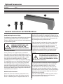
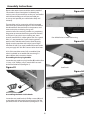
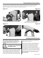
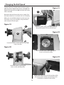
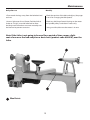
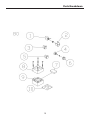
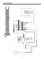
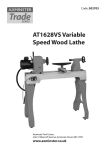
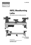
Code: 501214
AT1416VS
Woodturning Lathe
The AW1416VS utilises the very reliable inverter
technology usually found on much larger machines
Electronic variable speed is a desirable feature for woodturners, enabling fine
tuning of speed to suit larger diameters or out of balance work pieces.
Axminster Tool Centre,
Unit 10 Weycroft Avenue, Axminster, Devon EX13 5PH
www.axminster.co.uk
Index of Contents
Index of Contents
02
Declaration of Conformity
02
What’s in the Box
03
Optional Accessories
04
General Instructions for 230V Machines
04-05
Specific Safety Instructions for Woodturning Lathes
05
Specifications05
Assembly Instructions
06-07
Illustration and Description
08-09
Indexing Operation
10
Removing Drive/Live Centres
11
Changing the Belt Speed
12
Maintenance13
Parts Breakdown
14-15
Parts Lists 1-2-3
16-17-18
AW1416VS Lathe Stand (Optional)
19
Wiring Diagram
20
Declaration of Conformity
Copied from CE Certificate
Manufactured by The Kingcraft Machinery Company
Limited is in compliance with the following standards
or standardisation documents in accordance with
Council Directives
The undersigned, authorised by Calvin Chou
The Kingcraft Machinery Company Limited
No. 26 Chung Gong Yeh 12 rd, Da-Li City, Taichung
County, Taiwan declares that this product:
Machinery Directive: 2006/42/EC
Low Voltage Directive: 2006/95EC
Electromagnetic Compatibility Directive:
2004/108/EC
Woodturning Lathes
1643INV, 1417, 1643, 1417INV, 1430,
1430INV, 1443, 1443INV, 1643INV
machine safely and to maintain its efficiency and
prolong its life. Keep this Instruction Manual readily
accessible for any others who may also be required to
use the machine.
Please read the Instruction Manual prior to using
your new machine; as well as the operating
procedures for your new machine, there are
numerous hints and tips to help you to use the
Warning
Fully read manual
and safety instructions
before use
Ear protection
should be worn
The symbols below advise that you follow
the correct safety procedures when using
this machine.
Eye protection
should be worn
2
Dust mask
should be worn
HAZARD
Motor gets hot
What’s Included
Quantity
Item 1 No AT1416VS Woodturning Lathe ( Headstock and Tailstock fitted)
1 No Tool Rest Arm (Fitted to Lathe Bed)
1 No 152mm Tool Rest (Fitted to Tool rest Arm)
1 No 80mm Faceplate (Fitted to Headstock)
A
1 No 4 Prong Drive Centre (Fitted to Headstock)
B
1 No Live Centre (Fitted to Tailstock)
Model Number
1417INV
Packet Containing
1 No 1 No 2 No 1 No 2 No 1 No 1 No Push Rod
8mm Hex Key
Steel Carryng Handles with four 1/4 unc x 5/8" Phillips Screws
24 Index Pin with Magnetic Base
Steel Hooks & (4) Phillips Screws
Instruction Manual
Guarantee Card
C
D
E
F
G
Having unpacked your new AT1416VS woodturning lathe please dispose of the unwanted
packaging responsibly. The cardboard packaging is biodegradable
E
G
C
D
F
A
3
B
Optional Accessories
Quantity
Item 1 No 2 No
Extension Bed (Product code: 951249)
5/16” x 1” Caphead Bolts & Spring/washer
H
I
H
I
General Instructions for 230V Machines
that you have unimpeded access to all parts of the
machine. The machine is designed for indoor use, do
not use when or where it is liable to get wet. Keep the
machine clean; it will enable you to more easily see
any damage that may have occurred.
Good Working Practices/Safety
The following suggestions will enable you to observe
good working practices, keep yourself and fellow
workers safe and maintain your tools and equipment
in good working order.
Clean the overall machine with a damp soapy cloth
if needs be, do not use any solvents or cleaners, as
these may cause damage to any plastic parts or to
the electrical components. Clean the machine
components with a lightly oiled cloth. If the machine
is liable to be standing idle for any length of time
a light coat of machine or spray oil will minimise
rusting.
WARNING! KEEP TOOLS AND
EQUIPMENT OUT OF THE
REACH OF YOUNG CHILDREN
Primary Precautions
These machines are supplied with a moulded 13
Amp. Plug and 3 core power cable. Before using the
machine inspect the cable and the plug to make sure
that neither are damaged. If any damage is visible,
have the tool inspected/repaired by a suitably
qualified person. If it is necessary to replace the plug,
it is preferable to use an ‘unbreakable’ type that will
resist damage. Only use a 13 Amp plug, and make
sure the cable clamp is tightened securely. Fuse as
required. If extension leads are to be used, carry out
the same safety checks on them, and ensure that they
are correctly rated to safely supply the current that is
required for your machine.
Keep the work area as uncluttered
as is practical, this includes personnel
as well as material. Under no circumstances should CHILDREN be allowed
in work areas.
It is good practice to leave the machine unplugged
until work is about to commence, also make sure
to unplug the machine when it is not in use, or
unattended. Always disconnect by pulling on the
plug body and not the cable. Once you are ready to
commence work, remove all tools used in the setting
operations (if any) and place safely out of the way.
Re-connect the machine.
Carry out a final “tightness” check e.g. chuck or face
plate, work piece, tool rest, etc., check that the
correct speed has been selected.
Work Place/Environment
Make sure when the machine is placed that it sits
firmly on the bench or stand, that it does not rock,
that it is sufficiently clear of adjacent obstacles so
4
General Instructions for 230V Machines
Make sure you are comfortable before you start work,
balanced, not reaching etc.
likewise, consideration should be given to the
removal of rings and wristwatches, if these are liable
to be a ‘snag’ hazard. Consideration should also be
given to non-slip footwear, etc.
If the work you are carrying out is liable to generate
flying grit, dust or chips, wear the appropriate safety
clothing, goggles, gloves, masks etc. If the work
operation appears to be excessively noisy, wear
ear-defenders. If you wear your hair in a long style,
wearing a cap, safety helmet, hairnet, even a
sweatband, will minimise the possibility of your hair
being caught up in the rotating parts of the tool,
DO NOT work with cutting tools of any description if
you are tired, your attention is wandering or you
are being subjected to distraction. A deep cut, a
lost fingertip or worse; is not worth it! Above all,
OBSERVE…. make sure you know what is happening
around you, and USE YOUR COMMON SENSE.
Specific Safety Instructions for Woodturning Lathes
1. Do not use ‘split’ work pieces.
must ensure that the mounting accessories (chucks,
faceplates etc.,) can be ‘locked’ onto the lathe
mandrel, and in the case of chucks have some form of
security device to prevent them ‘unwinding’ during
reverse operation.
2. Always start at the lowest speed when starting a
new task.
3. Check that the tool rest is at or slightly below the
centre line of the workpiece.
8. Make sure your tools are stored/racked away from
the turning area of the lathe. Do not reach over a
rotating work piece at any time.
4. Check the work piece is securely mounted in the
lathe before switching on the power.
9. Do not ‘dig in’ or try to take too large a cut.
5. Rotate the work piece by hand, to check that it
is centralised, clear of the tool rest, not ‘split’ or has
loose knots.
10. Do not leave the lathe running unattended; or
leave the machine until everything is stopped.
6. Where lathes have the facility to be reversed;
check the machine is rotating in the correct
direction.
11. Some turning tools may have specific sharpening
angles that have been determined by the
manufacturers; when re-sharpening, adhere to these
angles to maximise the finish of your work.
7. If your lathe has the facility to run in reverse, you
Specification
Product Code
501214
ModelAT1416VS
RatingTrade
Power
230V 50Hz 560W
Speed
0-800, 200-1,750, 400-3,600rpm
Spindle Taper
2MT
Spindle Thread
M33 x 3.5mm (Ref T38)
Taper Tailstock
2MT
Distance Between Centres
400mm
Max Diameter over Bed
350mm
Tool Rest Stem Diameter
25.4mm
Overall L x W x H
865 x 330 x 415mm (With Extension Bed: 1,465 x 330 x 415mm)
Weight41kg
5
Assembly Instructions
Please take some time to read the section entitled
“Illustration & Parts Description” to identify the
various parts of your machine so that you are familiar
with the terminology we will use to enable you
to set up and operate your table lathe safely and
correctly.
Figure 02
The machine and its accessories will arrive coated
with corrosion preventative grease. This will need to
be cleaned from the machine, its components and
accessories prior to it being set up and
commissioned. Use coal oil, paraffin or a proprietary
de greaser to remove the barrier grease. Be warned,
it will stain if you splash it on clothing etc., wear
overalls, coverall et al., rubber gloves are also a good
idea, as is eye protection if your cleaning process
tends to be a little bit enthusiastic. After cleaning,
lightly coat the machine with a thin layer of light
machine oil. N.B If you used paraffin/kerosene make
sure you apply this thin film sooner rather than later.
Pre-drilled holes in lathe bed casting
Figure 03
95% of the machine comes fully assembled, (See
what’s included) to assemble the remaining 5%
please follow the instructions below.
Assembling the Carrying handles
Locate the two steel carrying handles (E) and the four
1/4 unc x 5/8" Phillips screws, attach them to each
end of the lathe bed (See figure 1).
Figure 01
Steel hook
Figure 04
E
Assembling the Power Cable Hooks
Steel hooks in position
Locate the two steel hooks & Phillips screws (G) and
screw them with the hooks facing inwards, into the
pre-drilled holes in the lathe bed. (See figures 2-3-4)
6
Assembly Instructions
Attaching the Optional Extension Bed (951249)
Figure 05
Figure 07
Step 1: Remove the carrying handle from the
end of lathe bed and place safely aside
I
Figure 06
Figure 08
H
Step 2: Line-up the pre-drilled holes in the
extension bed (H) with the holes in the lathe
Step 3: Locate the two 5/16 unc x 1” caphead bolts and spring/washers (I), Slot them through the holes in the
extension bed (H) & lightly screw them into the lathe bed, using a Hex key. Clamp the tailstock over
the two beds and adjust until both beds are aligned then tighten the bolts, (DO NOT OVERTIGHTEN).
(See figures 7-8) Replace the carrying handle (E) and screws to the end of the extension bed (H).
AT1416VS Lathe
Extension Bed
7
Illustration and Description
Tailstock barrel lock
Drive centre
Access panel
Access panel lock
Live centre
Tailstock lock
Power cable hooks
Lathe bed
Motor
Headstock wheel
Electronic inverter
control unit
Headstock
Faceplate
Tailstock wheel
Tool rest
Tool rest lock
Carrying
handle
Banjo lock
Motor handle
Banjo
Lift and shift clamping handle
Green (ON)
Spindle speed LED
8
Red (OFF)
Forward/Reverse switch
Speed control knob
Illustration and Description
Electronic Inverter Control Unit
General Purpose AC Micro Drive from “Delta
Electronics”. The VFD-S drive is famous for its low
noise carrier frequency feature and easy to use
keypad. The digital keypad comes in two parts; the
display panel and keypad. The display provides the
parameter display and shows operation status of the
AC drive. The keypad provides programming
interface between the user and the AC drive. For
more information see manufacturer’s manual.
Note: The inverter comes preset from the factory and you should not need to make any adjustments.
9
Indexing Operation
The indexing facility is useful for fluted columns, clock faces and accurate hole positioning. The indexing
pulley has 24 positions (15°) indexing using the supplied index pin (F).
Figure 09
1-24 index positions
Figure 10
Open the access panel, turn the headstock wheel until the pre-drilled hole in the headstock lines up
with one of the 24 pre-drilled hole positions on the index pulley. (See figs 9-10-11)
Figure 11
Figure 12
Pre-drilled hole
F
Locate the 24 index pin (F) and slide the pin into the pre-drilled
holes to lock the pulley to the desired position
Figure 13
Figure 14
The picture above shows the index
The picture above shows the index
number is set to position 01
number is set to position 23
Note: The index pin (F) has a magnetic base, enabling the pin to
be attached to the lathe to prevent it from being lost.
10
Removing Drive/Live Centres
To remove the Drive Centre (A), locate the push rod (C), while holding the tool insert the push rod (C)
through the centre hole of the headstock wheel and push the drive centre out. (See figs 15-16-17)
Repeat the procedure for the Live Centre in the tailstock. (See fig 18)
Figure 15
Figure 16
C
Insert the push rod (C) through the
headstock and push the drive centre out
Centre hole in the headstock operating wheel
Figure 17
Figure 18
A
Removing the drive centre
Live centre in tailstock
Changing the Belt Speed
Note. The lowest speed pulley combination is
furthest from the faceplate, i.e. smallest motor
pulley diameter to largest spindle pulley
diameter.
DISCONNECT THE LATHE FROM
THE MAINS SUPPLY!
Lower the access panel (A) on the headstock by
loosening the access panel lock caphead screw (B),
using a Hex key. (See figs 19 & 20) Open the motor
access door (C), by pulling the spindle speed LED
box towards you. (See fig 21) Loosen the motor’s lift
& shift handle, see fig 23, lift the motor plate handle
to give enough slack in the belt to enable it to be
moved to the new selection.
When the belt is located, turn the spindle to ensure
the belt is correctly seated. Check that the belt is
vertical, the belt must not be run out of vertical
alignment, this can cause the belt to ‘jump’ the
pulley grooves, possibly the wrong way, and if it
does manage to run, it will scuff the sides of the belt
badly). When you are sure all is correct, press down
on the motor plate handle to put tension on the belt.
Note: The belt does not need to be bar taut to
operate correctly.
11
Continues Over...
Changing the Belt Speed
Tighten the lift and shift handle to hold the motor
plate in position. Replace the access panel (A) and
tighten the caphead screw (B) and close the motor
access door (C).
Figure 21
C
Reconnect the machine to the mains supply. Give
the lathe a little ‘burst’ to check it all runs smoothly.
When you are satisfied, remove any tools you may
have been using; stow carefully away, the lathe is
now ready to be used again.
Figure 19
B
Open the motor access door (C), by pulling
the spindle speed LED box towards you.
Figure 22
A
Loosen the access panel caphead screw (B)
using a Hex key.
Figure 20
With the motor access door open, gives
access to the motor pulley.
Figure 23
Lower the access panel to give
access to the spindle pulley
Loosen the motor’s lift and shift handle and lift
the motor plate handle to give enough slack
in the belt to enable it to be moved.
12
Maintenance
Daily after use
Monthly
•Clean wood shavings away from the lathe bed and
tool rest.
•Check the tension of the belt and adjust, (See pages
11 & 12 for Changing the Belt Speed).
•Smear a light coat of wax (Protec Tool Wax Polish,
Order no. 211835 ) over the lathe bed to allow
the Banjo and Tailstock to run more smoothly over
the bed and to prevent corrosion.
•Check any build up of wood shaving on the motor
and spindle pulley’s and clean if necessarily.
• Using an airline, blow out the motor’s air vent.
Note: If the lathe is not going to be used for a period of time, smear a light
coat of wax over the bed and place a dust sheet (product code. 600410), over the
lathe.
Wax Points
13
Parts Breakdown
14
Parts Breakdown
15
Parts List 1
16
Parts List 2
17
Parts List 3
18
AW1416VS Lathe Stand (Optional)
AW1416VS Lathe Stand (Product Code: 951248)
1
LEG BASE
1
2
LEG SUPPORT
1
3
LEG BAR
4
HEX SCREW
1
1.4" - 1/2"
12
5
WASHER
1/4"
12
6
CAP SCREW
3/8"- 1"
4
3/8"
7
WASHER
8
WHEEL
4
2
9
FOOT
3/8"
2
10
NUT
3/8"
2
11
NYLON NUT
5/16"
2
12
WASHER
5/16"
2
13
HEX SCREW
5/16"- 65MM
2
19
Wiring Diagram
20