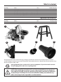
1
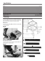
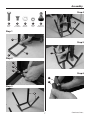
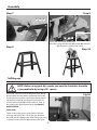
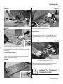
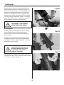
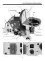
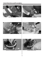
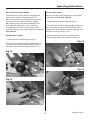
Code 501188
SS-12VS 305mm
Disc Sander
Index of Contents
Index of Contents
02
Declaration of Conformity
02
What’s Included
03
General Instructions for 230V Machines
04
Specific to Sanding Machines
05
Specification06
Assembly06-07-08
Setting up
08-09-10
Parts Illustration and Description
11-12
Operating Instructions
13-14
Changing the Abrasive Disc
14-15
Maintenance16
Trouble Shooting
17
Parts Breakdown/List
18-19-20-21
SS-12VS Wiring Diagram
22
Notes23
Declaration of Conformity
Manufactured by KINGCRAFT MACHINERY COMPANY
LIMITED. is in compliance with the standards
determined in the following Council Directive.
Copied from CE Certificate
The undersigned, N. Sifonios authorised by
EN 60204-1:2006+A1: 2009
EN ISO 12100: 2010
KINGCRAFT MACHINERY COMPANY LIMITED.
No.26, Gong Yeh 12rd, Dah Li District, Taichung City,
Taiwan
Low Voltage Directive: 2006/95/EC
Machinery Directive: 2006/42/EC
Model Number SS-12VS (Disc Sander)
Warning
Fully read manual
and safety instructions
before use
Ear protection
should be worn
The symbols below advise that you follow
the correct safety procedures when using
this machine.
Eye protection
should be worn
2
Dust mask
should be worn
HAZARD
Motor gets hot
What’s Included
Quantity
Item Part
1 No
1 No
1 No
1 No
1 No
SS-12VS Disc Sander
Mitre Fence
Dust Extraction Adaptor (63mm to 37mm)
Dust Extraction Adaptor (63mm to 100mm)
Instruction Manual
A
B
C
D
Model Number
SS-12VS
Optional Accessories
Quantity
1 No
Item Stand
Part
E
A
Product Code
501189
E
C
B
D
Having opened the box, remove the top packaging and lift the machine out and place upon a clear flat
surface, taking care not to trap or pinch the power cable under the chassis. Remove the remaining items from
the box and place safely aside.
Having unpacked your sander and its various components, if you do not wish to retain
the packaging please take it to a recycling centre.
NOTE: Please read the Instruction Manual prior to using your new machine; as
well as the operating procedures for your new machine, there are numerous
hints and tips to help you to the machine safely and to maintain its efficiency
and prolong its life. Keep this Instruction Manual readily accessible for any
others who may also be required to use the machine.
3
General Instructions for 230V Machines
the disc, put in a ‘plastic’ bag and store in a warm
dry place. With regard to the disc, this advice is on
practical if you have upgraded to a Velcro fastening
method. Also ensure that spare belts/discs are not
stored in damp conditions.
Good Working Practices/Safety
The following suggestions will enable you to observe
good working practices, keep yourself and fellow
workers safe and maintain your tools and equipment
in good working order.
Keep the work area as uncluttered as is practical; this
includes personnel as well as material.
WARNING! KEEP TOOLS AND
EQUIPMENT OUT OF THE
REACH OF YOUNG CHILDREN
UNDER NO CIRCUMSTANCES
SHOULD CHILDREN BE
ALLOWED IN WORK AREA
Disc Sander
Primary Precautions
Specific to Sanding Machines
These machines are supplied with a moulded 13
Amp. plug and 3 core power cable. Before using the
tool inspect the cable and the plug to make sure that
neither are damaged. If any damage is visible have
the tool inspected/repaired by a suitably qualified
person. If it is necessary to replace the plug, it is
preferable to use an ‘unbreakable’ type that will resist
damage on site. Only use a 13 Amp plug, make sure
the cable clamp is tightened securely. Fuse at 13
Amp. It is also good practice to use switched outlets.
If extension leads are to be used, carry out the same
safety checks on them, and ensure that they are
correctly rated to safely supply the current that is
required for your machine. This machine is intended
primarily for inside/workshop usage.
Once the sander is mounted, carry out any setting
operations and remove all tools used in the setting
operations (if any) and place safely out of the way. If
you are working long lengths of material, arrange for
extra support beyond the boundary of the machine,
and check you have sufficient room to manoeuvre
the material through all the operations you will wish
to carry out.
It is good practice to leave the machine unplugged
until work is about to commence; also make sure
to unplug the machine when it is not in use. Always
disconnect by pulling on the plug body and not the
cable.
Work Place/Environment
After fitting a new sanding disc, it is good practice
to lightly sand across the left side of the disc with a
reasonable sized (20mm x 50mm) piece of timber to
make sure the sanding disc is correctly ‘seated’ on the
disc. The sanding action will press the sanding disc
firmly back against the disc itself.
Always mount the machine on a flat, level stable
surface. There are several methods of achieving
this; bolting the machine directly to a ‘good solid
workbench’; bolting the machine to a sturdy base
board that can be clamped to the ‘good solid
workbench’; create an independent entity by bolting
the machine to its own stand. However you mount
your machine, make sure it is secured down and
stable before use.
DO NOT sand very small pieces of work with bare
hands; try to construct some form of holder.
Make sure you are comfortable before you start
work, balanced, not reaching etc. If the work you are
carrying out is liable to generate excessive grit or
dust or chips wear the appropriate safety clothing,
goggles, masks etc. If the work operation appears
to be excessively noisy wear ear-defenders. If you
wear your hair in a long style wearing a cap, safety
helmet, hair net, even a sweatband, will minimise
the possibility of your hair being caught up in the
rotating parts of the machine. Likewise,
Paper belts and discs do not respond well to wet or
damp conditions. In the worst case the adhesives
holding the belt and the abrasive fail completely, the
belts fall apart and the abrasive becomes a soggy
mess against the edge of your workpiece.
Try to keep the machine in a reasonably dry, warm
environment. If this is not possible, or if the machine
is to remain unused for some time, at least remove
4
Specific to Sanding Machines
consideration should be given to the removal of
rings and wristwatches if these are liable to be a
‘snag’ hazard.
Do not press too heavily against the sanding surface,
all this will do is slow the sander down. Remember,
sanders work by removing small particles of material
quickly and heavy pressure works adversely to the
cutting process. Further, it will accelerate the rate
of ‘clogging’ of the abrasive surfaces, rendering the
machine less efficient.
Do not work with cutting/abrasive tools of any
description if you are tired, your attention is
wandering or you are being subjected to distraction.
If you are attempting to sand inside curves (over
the ‘tracking drum’) do not press at all, other than to
keep the workpiece in contact with the surface, any
pressure could upset the tracking geometry. As there
is no cushioning effect to the belt passing around the
drum, expect an added vibration and compensate
for it.
Do not use the machine within the designated safety
areas of flammable liquid stores or in areas where
there may be volatile gases.
Check that sanding surfaces are still sufficiently
abrasive to carry out the work you intend. Sanding
belt cleaning sticks are an efficient method of
prolonging the life of the belts and discs and will also
maintain their operating performance.
Sanding of certain types of timber may make the
fitting of dust extraction mandatory in order to
comply with the directives of the HSE. However, even
if it is not mandatory, it is strongly recommended that
you consider fitting dust extraction. It will certainly
reduce the level of dust and grit, and as it helps to
remove the waste quicker will certainly prolong the
longevity of the abrasive.
Check that the belts or discs are undamaged;
torn edges can pick up on the workpiece and will
cause the medium to tear, often very rapidly with
accompanying sharp flapping edges.
Always offer the workpiece to the belt/disc so that
the motion carries the work against the restraining
surface i.e. the work stop or the table (use the left
hand side of the disc).
Above all, OBSERVE…. make sure you know what
is happening around you, and USE YOUR COMMON
SENSE.
5
Specification
ModelSS-12VS
Product Code
501188
RatingTrade
Power
750W (230V, 1ph)
Speed
1,000 - 3,000rpm
Diameter of Disc
305mm (12")
Table Size
300 x 225mm
Table Tilt
-5° to +45°
Dust Extraction Outlet
63mm
Overall L x W x H
650 x 400 x 430mm
Weight32kg
Assembly
The disc sander comes fully assembled except the
mitre fence (B) and the dust extraction adaptor (C).
Please follow the assembly instruction below.
Optional Stand Assembly
A
B
Mitre Fence
1
Locate the mitre fence (B) and slide it into the tables
‘T’ slot, see fig 01.
3
Fig 01
4
2
C
C
B
5
E
B
6
D
D
1
Dust Extractor Adaptor
Locate the dust extractor adaptors (C) or (D), insert it
into the 63mm sander outlet.
2
Fig 02
3
C
4
5
6
6
Assembly
Step 4
A
E
B
C
D
X4 M8
Bolts
X24 M8
Coach Bolts
X32 M8
Washers
X28 M8
Nuts
X4 Thread
Rubber Foot
4
Step 1
3
Step 5
5
1
2
Step 2
E
B
C
Step 6
6
D
Step 3
B
7
Continues Over...
Assembly
Step 7
Step 9
E
B
C
6
A
B
C
Lower the disc sander on top of the stand and line up
the holes, using the four bolt (A) washer (B) and Nuts
(C) secure the sander to the stand
Step 8
Step 10
Setting up
NOTE: Before using your disc sander you need to check that the table
is perpendicular by using a 90˚ square.
Place a 90˚ square on the sanding disc table, see fig
03 and check that the table is perpendicular to the
sanding disc. If it requires adjustment loosen the tilt
mechanism clamp (a), see fig 04 and turn the rise
and full control knob (b) until the table is at 90˚ to
the sanding disc then tighten clamp (a). DO NOT
OVERTIGHTEN
Fig 03
Table Stops
There are two adjusting nuts to the base of each
table leg, see fig 05. This is to set the gap between
the table and disc. Release the table clamps (c), using
a spanner loosen the nuts (d) and adjust the grub
8
Setting up
Fig 04
Fig 07
a
b
Using a square adjust the table until it is set to 90˚ to
the disc. Re-tighten the hex bolts.
Fig 05
Scale Pointer
Now the table is set correctly you may have to adjust
the pointer on the scale so it’s set to (0˚) degrees.
Loosen the Phillips screw and adjust until correct,
re-tighten the screw. (see fig 06)
c
d
Fig 08
e
screw stops (e) so the table does not come into
contact with the sanding disc, tighten the nuts to
lock the table stops in position. Re-tighten the table
clamps (c).
Table Top Adjustment
The table top can be adjusted so it’s square to the
sanding disc. Using a Hex key loosen the two Hex
bolts in the table, see fig 6.
Loosen the Phillips screw and line up the pointer so it
reads (0˚) degrees on the scale.
Fig 06
Your disc sander is now ready. Check that all fixings
are secure before operating the machine.
CONNECT THE SANDER TO
THE MAINS SUPPLY
9
Continues Over...
Setting up
Remove all tools away for the machine, Switch on,
wait until the machine has reached full speed and
check that the disc sander is running properly ie, no
vibration or rattling for example. If not, switch off,
wait for the machine to come to a complete stop,
disconnect the sander and check all fixing to make
sure they are tight. Reconnect, switch on and check
again. If everything is fine, switch off and wait until
the machine has come to a complete stop.
Fig 09
DISCONNECT THE SANDER
FROM THE MAINS SUPPLY
C
Dust Extraction
The dust extraction moulding has a 63mm outlet,
insert a jubilee clip over the general purpose
extraction hose and insert it over the outlet and
clamp in place.
Fig 10
Also the disc sander comes with two adaptors (C)
and (D) see figs 09-10. Fit a general purpose hose
with either a 37mm or 100mm diameter and with a
jubilee clip, secure in place.
DO NOT OVERTIGHTEN AS THE
EXTRACTION OUTLET IS ONLY
PLASTIC AND CAN CRACK IF
DONE UP TOO TIGHT.
Fig 11
Alternately, if you have a vacuum cleaner with the
same diameter hose insert it over the outlet as before,
it should be a snug fit. (see fig 11)
Vacuum cleaner hose connected to sanders adaptor
10
Parts Illustration and Description
Disc guard
Sanding Disc
Manual disc brake
Table
Motor
Handle
Mitre fence
Table stop
63mm Dust
extraction outlet
Control panel
Rise and fall control knob
Tilt handle lock
Table clamp handle
a
b
On/Off NVR switch assembly, (I) on and (O) off
6 AMP OVERLOAD TRIP SWITCH (a)
and speed control knob (b)
11
Parts Illustration and Description
Tilt mechanism scale
c
Tilt mechanism scale pointer
d
Pre-set/Index stops (c) and preset stop pin (d)
Table stop adjuster
f
e
Mitre fence scale (e) and pointer (f)
Rotating the mitre fence
12
Operating Instructions
Rise and Full Control Assembly
Pre-set/Index system
The table on this sander remains level whilst the
whole motor and disc arrangement tilts. This
allows your work to stay level, improving accuracy
and safety. The disc can be tilted from -5° to +
45°, enabling many tasks to be undertaken. The
disc angles are adjusted by a rack and pinion
arrangement, plus there is a quick action index
system enabling you pre select angles from -5, 0, 15,
22.5, 30 & 45°.
The Pre-set/index system enables you to pre select
angles from -5, 0, 15, 22.5, 30 & 45°.
Tilting the Disc Sander
3. While holding the Index Pin in, tighten the tilt
handle lock (a), release the Index Pin. (see fig 15)
1. Unlock the tilt handle lock (a). (see fig 12)
2. Turn the rise and full control knob (b), see fig 13 at
the same time pressing in the Index Pin (c), until it
engages into one of the pre-set holes (d) in the rack
and pinion casting. (see figs 14-15)
1. Unlock the tilt handle lock (a), see fig 12.
Fig 14
2. Twist the rise and fall Control knob (b), until you
have the correct angle. Then lock the assembly in
place with the locking handle (a). (see fig 12-13)
d
Fig 12
c
Fig 15
a
Fig 13
b
13
Continues Over...
Operating Instructions
Variable Disc Speed
Fig 17
The motor on this machine is a 750W DC brush type
unit, electronically controlled to give a disc speed
of between 1,000-3,000rpm. This means that you
can choose the disc speed that is right for the job,
whatever the material. Disc speed is maintained
electronically to compensate for work loads.
Manual Disc Brake
A manual disc brake is fitted to allow the disc to be
stopped quickly if required. (see fig 16)
Fig 16
Undo the tables two clamping handles
on either side and lower the table
Fig 18
Changing the Abrasive Disc
DISCONNECT THE SANDER
FROM THE MAINS SUPPLY!
1. Release the two clamping handles on either side
of the table and lower the table carefully and remove
the extraction adaptor, see figs 17-18.
Fig 19
2. Loosen the two butterfly screws on either side of
the extraction moulding and lower carefully down.
(see figs 19-20). (You may need to tilt the sander to
lower the extraction moulding fully)
3. Remove the disc guard by undoing and removing
the two Phillips screws and place safely aside. (see
fig 21)
NOTE: BE CAREFUL WHEN REMOVING
THE SCREWS AS THERE ARE TWO
PLASTIC SPACERS BETWEEN THE DISC
GUARD AND THE REAR MOULDING!
Undo the two butterfly screws on either side of the disc
14
Changing the Abrasive Disc
sanding disc and evenly press down, making sure
there are no wrinkles or air bubbles. (see figs 22-23)
Fig 20
6. Replace the disc guard, extraction moulding and
table.
Fig 22
Lower the extraction moulding
Fig 21
Peal off the old abrasive disc and place aside
Fig 23
Disc guard plastic spacer
Offer up the new abrasive disc and press
down evenly onto the sanding face
WEAR A DUST MASK WHEN
CHANGING THE ABRASIVE
DISC!
4. The abrasive disc is attached to the sanders face
by Velcro, a strip of fabric that cling when pressed
together. Simply peal off the old abrasive disc, you
may need to use a hand brush to brush off any loose
saw dust on the disc face.
5. Line up the new abrasive disc with the face of
CONNECT THE SANDER TO
THE MAINS SUPPLY!
Start up the sander, wait until it’s at full speed and
look to see if the abrasive disc is spinning evenly
around. If NOT switch off, wait until the sander comes
to a complete stop and repeat the procedure from
the opposite page until the disc is spinning correctly.
15
Maintenance
DISCONNECT THE SANDER FROM THE MAINS SUPPLY!
There is very little mechanical maintenance that
can be carried out on the machine. Most prudent
maintenance is preventative and concerned with
keeping the machine clean.
WEAR A DUST MASK WHEN
CLEANING THE SANDER!
Fig 24
1. At reasonable intervals, inspect and remove all dust
and resin build up, clean the motor assembly.
2. Lower the dust extraction moulding and remove
any dust or resin build up and clean thoroughly. (see
fig 24-25)
Fig 25
Lower the table
Lower the dust extraction moulding and
clean any build up of dust or resin
16
Trouble Shooting
PROBLEM
Motor will not run
POSSIBLE CAUSE
1. Defective or broken
“ON -OFF” switch
REMEDY
1-3. Replace all broken or
defective parts before using
the sander
2. Defective or damaged
switch cord
3. Defective or damaged
switch relay
4. Contact Axminster Tool
Centre on 03332 406406 and
asked to be transferred to
the “Technical Enquiries”
Department
4. Burned out motor
5. Blown fuse
6. Motor has cut out or stalled
6. Press the 6 AMP OVERLOAD
TRIP SWITCH
Machine slows down
while sanding
1. Applying too much pressure
to workpiece
1. Apply less pressure to
sanding surface
Wood burns while
sanding
1. Sanding disc is worn
1. Replace the disc
2. Excessive pressure being
applied to workpiece
2. Reduce pressure being
applied to workpiece
6 AMP OVERLOAD TRIP SWITCH
Above the speed control dial there is a “6 AMP OVERLOAD TRIP SWITCH”. If the sander stalls from too much
pressure being applied to the disc or the motor cuts out due to overheating or over use, press this switch to
reset the sander. (see fig 26)
NOTE: WAIT TWO MINUTES AFTER THE SANDER HAS STOPPED
BEFORE PRESSING THE OVERLOAD TRIP SWITCH TO ALLOW THE COMPONENTS TO COOL DOWN!
Fig 26
6 AMP OVERLOAD TRIP SWITCH
17
Parts Breakdown/List
18
Parts Breakdown/List
NO.
Description
Specification
QTY
1
Front cover
2
Knob
1/4”
2
3
Sanding Disc
12”-#80
1
3-1
Velcro paper
4
Flat HD Screw
1/4-20UNCX1/2”
11
5
Washer
1/4”-24
1
6
Disc Plate
12”
1
7
Hex Head Screw
1/4”X1/2”
6
8
Hex Socket Round HD Screw
1/4”-1/2”
7
9
Cap Screw
M4X55
1
10
Disc Tray
11
Nut
12
Brake Wagon
1
13
Brake Plate
1
14
Fixing Plate
1
15
Flat HD Screw
16
Brake Pin
1
17
Spring
1
18
Button
1
19
Motor Support
1
20
Motor
1
23
Hex Head Screw
24
Worktable
25
Cap Screw
5/16”-1”
2
26
Universal Handle
1/4”
1
27
Washer
1/4”-T=3MM
2
28
Knob
1
29
Hexagonal Rod
1
30
Index Pin
1
31
Spring
1
32
Sleeve
1
33
E-Ring
1
1
1
3/16”
3/16”X3/8”
1/4X1”
5
8
2
1
ETW-3
19
1
Parts Breakdown/List
34
Hex Socket Round HD Screw
1/4”X1”
4
35
Washer
4
36
Gear
2
37
Clamping Plate
2
38
Guide Block(R)
1
38B
Guide Block(l)
39
Washer
40
Angle Gauge Plate
40B
Angle Gauge Plate
41
Universal Handle
3/8”
2
42
Washer
3/8”
4
43
Rod
2
44
Bracket
1
1
1/4”
8
1
1
45
Nut
47
Control Panel
M8
1
48
Base
1
49
Strain Relief
50
Plate
51
Coil Spring
52
Main Switch
1
53
Power Cord
1
54
Pressure Plate
1
55
Nut
1
56
Round HD Cross Screw
57
Circuit Board
1
58
Insulating Film
1
59
Heat Sinks
1
60
Cheese Head Screw
5/16”x3/4”
1
61
Cheese Head Screw
M4X12nn
1
62
Knob
1
63
VR
1
64
Circuit Breaker
1
65
Wire-Short
1
PG9
2
2
1
1/4”
M3X12mm
20
11
6
Parts Breakdown/List
66
Insulating Paper
1
67
Space Block
4
68
Bottom Plate
69
Tooth Washer
70
Warning Label
71
Tapping Screw
72
Space Block
2
73
Safety Plate
1
74
Warning Label
75
Dust Chute
76
I.D. Label
1
77
Warning Label
1
78
Carry Handle
2
79
Key
6x6X25
1
80
Nut
M3
4
82
Dust Chute
2-1/4” to 4”
1
83
Guide Bush
84
Nylon Nut
M4
1
85
Set Screw
1/4”x35mm
2
86
Nut
1/4”
2
87
Cheese Head Screw
3/16”x1/2”
4
90
Washer
M4
1
91
Pointer
92
Circuit Board
93
Angle Guide
1
94
Rod
1
95
Motor Label
1
96
Hex Screw
3/8”-2”
4
97
Nut
3/8”
2
1
3/16”
2
1
3/16”X1”
2
1
2-1/4” to1-1/2”
1
1
1
M4X5
21
1
SS-12VS Wiring Diagram
22
Notes
23
The Axminster guarantee is avalible on
Hobby, Trade, Industrial, Engineer, Air Tool & Axcnc Technology Series machines
It’s probably the most comprehensive FREE guarantee ever- buy with confidence from Axminster!
So sure are we of the quality, we cover all parts and labour free of charge for three years!
• Look for the icon and put your trust in Axminster
• No registration necessary - just keep your proof of purchase
• Optional Service Plan for Industrial Series machinery
Great value & easy-to-use,
perfect for use at home
Solid, reliable machines
designed for daily use
Top performers with class leading features and
build quality for use in busy workshops
Quality, precision machines
for the workshop or education
Small machines for the home
engineer
Compressors and tools for home or
workshop use, duable and great value
Free Three Year Guarantee on Axminster Hobby, Trade and Industrial Series
woodworking and engineering machines, Axminster Air compressors and Air
Tools, and bench top grinders - no registration necessary just proof of purchase.
We will repair or replace at our discretion and will collect only from a UK
mainland address, irrespective of the original delivery address
The Guarantee assumes that you have bought the correct machine for the
required operation, in accordance with our guidelines; have operated and
maintained it in accordance with the instruction manual; and that all cutting
machines will be used with a blade which is sharp and serviceable at all times.
It does not cover consumable items purchased with the original product,
including original blades or abrasives
Pecision CNC machines for
industry and education
Normal wear and tear, misuse, abuse and neglect are excluded and the machine
should not have been modified in any way. Please do not attempt to service the
product without first contacting us; we are happy to guide you but failure to do
so may invalidate the guarantee
The Guarantee is transferrable from owner to owner in the first three years but
you must have original proof of purchase. Should we need to replace a machine
in the first three years the guarantee will still continue to be effective from the
original purchase date
Full Terms and Conditions can be found here. This guarantee does not affect
your statutory rights.
for more information visit axminster.co.uk/3years
Please dispose of packaging for the product in a responsible manner. It is suitable for recycling.
Help to protect the environment, take the packaging to the local recycling centre and place into
the appropriate recycling bin.
Only for EU countries
Do not dispose of electric tools together with household waste material. In observance of
European Directive 2002/96/EC on waste electrical and electronic equipment and its
implementation in accordance with national law, electric tools that have reached the end of their
life must be collected separately and returned to an environmentally compatible recycling facility.
Axminster Tool Centre,
Unit 10 Weycroft Avenue, Axminster, Devon EX13 5PH
axminster.co.uk