1
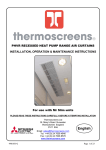
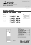
Air-Conditioners
PEA-RP·EA / PUHZ-RP·HA
FOR USER (FOR INSTALLER)
OPERATION
MANUAL
For safe and correct use, please read this operation manual thoroughly before operating the air-conditioner unit.
Contents
1. Safety Precautions
1
1. Safety Precautions ....................................................................................
2. Operation ...................................................................................................
2.1. Switching the unit on/off ..............................................................
2.2. Mode select .................................................................................
2.3. Selecting a temperature TEMP. .....................................................
2.4. Selecting a fan speed
..........................................................
2.5 Using the timer ............................................................................
3. Care and cleaning .....................................................................................
3.1. Cleaning the filters and the indoor unit ........................................
4. Troubleshooting .........................................................................................
5. Specifications ............................................................................................
2
3
3
3
4
4
4
5
5
6
7
s Before installing the unit, make sure you read all the “Safety precautions”.
s The “Safety precautions” provide very important points regarding safety.
Make sure you follow them.
s This equipment may cause the adverse effect on the same supply system.
s Please report to or take consent by the supply authority before connection to the system.
Symbols used in the text
Warning:
Describes precautions that should be observed to prevent danger of injury or
death to the user.
Caution:
Describes precautions that should be observed to prevent damage to the unit.
Symbols used in the illustrations
: Indicates an action that must be avoided.
: Indicates that important instructions must be followed.
: Indicates a part which must be grounded.
: Indicates that caution should be taken with rotating parts.
: Indicates that the main switch must be turned off before servicing.
: Beware of electric shock.
: Beware of hot surface.
ELV :
At servicing, please shut down the power supply for both of Indoor Unit and
Outdoor Unit.
Warning:
Carefully read the labels affixed to the main unit.
Warning:
• The unit should not be installed by the user. Ask the dealer or an authorized
company to install the unit. If the unit is installed improperly, water leakage,
electric shock or fire may result.
• Do not stand on, or place any items on the unit.
• Do not splash water over the unit and do not touch the unit with wet hands.
An electric shock may result.
• Do not spray combustible gas close to the unit. Fire may result.
• Do not place a gas heater or any other open-flame appliance where it will be
exposed to the air discharged from the unit. Incomplete combustion may
result.
Caution:
• Do not use any sharp object to push the buttons, as this may damage the
remote controller.
• Never block or cover the indoor or outdoor unit’s intakes or outlets.
MITSUBISHI
CENTRAL
LY CONTROL
LED
CHECK
ON OFF
ON/OFF –
1Hr.
CLOCK
˚C
STAND BY
DEFROST
NOT AVAILABLE
2
FILTER
CHECK MODE
˚C
TEST RUN
1. Safety Precautions
2. Operation
1
Warning:
• Do not remove the front panel or the fan guard from the outdoor unit when it
is running.
• When you notice exceptionally abnormal noise or vibration, stop operation,
turn off the power switch, and contact your dealer.
• Never insert fingers, sticks etc. into the intakes or outlets.
• If you detect odd smells, stop using the unit, turn off the power switch and
consult your dealer. Otherwise, a breakdown, electric shock or fire may result.
• This air conditioner is NOT intended for use by children or infirm persons
without supervision.
• Young children should be supervised to ensure that they do not play with
the air conditioner.
• If the refrigeration gas blows out or leaks, stop the operation of the air conditioner, thoroughly ventilate the room, and contact your dealer.
Disposing of the unit
When you need to dispose of the unit, consult your dealer.
Check if your remote controller is the wired type or the wireless type before referring
to the illustration and text for operation procedures.
2.1. Switching the unit on/off
• The power supply should not be turned off while the air conditioner is in use. This
can cause the unit to break down.
1 Press the ON/OFF button.
˚C
A The ON indicator should light up.
˚C
TEMP.
ON/OFF
A
1
FILTER
CHECK TEST
TIMER SET
• Even if you press the ON/OFF button immediately after shutting down the operation in progress, the air conditioner will not start for about three minutes. This is to
prevent the internal components from being damaged.
• If the operation stops due to a power failure, the unit will not automatically restart
until the power has been restored. Press the ON/OFF button to restart.
2.2. Mode select
1 If the unit is off, press the ON/OFF button to turn it on.
A The ON indicator should light up.
2 Press the operation mode (
mode.
) button and select the operation
B
s
B
˚C
Fan mode
˚C
TEMP.
Cooling mode
ON/OFF
A
1
FILTER
Heating mode
Drying mode
2
CHECK TEST
Automatic (cooling/heating) mode
TIMER SET
Note:
The heating display and the automatic display does not appear in models that
operate exclusively as cooling only air-conditioner.
3
2
2. Operation
2.3. Selecting a temperature
TEMP.
s To decrease the room temperature:
1 Press
button to set the desired temperature.
A The selected temperature is displayed.
2
• Each time you press the button, the temperature value decreases by 1 °C.
A
s To increase the room temperature:
1 Press
button to set the desired temperature.
˚C
˚C
A The selected temperature is displayed.
TEMP.
ON/OFF
• Each time you press the button, the temperature value increases by 1 °C.
1
FILTER
• Available temperature ranges are as follows:
CHECK TEST
Cooling & Drying:
19 - 30 °C
Heating:
17 - 28 °C
Automatic:
19 - 28 °C
Circulation:
— (Not available)
• The display flashes either 8 °C - 39 °C to inform you if the room temperture is lower
or higher than the displayed temperature.
TIMER SET
2.4. Selecting a fan speed
1 Press
button to select a desired fan speed.
• Each time you press the button, available options change with the display A on
the remote controller, as shown below.
A
Remote controller display
Fan speed
Low
˚C
˚C
▼
2-stage
TEMP.
High
▼
ON/OFF
FILTER
The display and the fan speed of the unit will differ in the following situations:
• When STAND BY and DEFROST are displayed.
• Just after the heating mode (while waiting to change to another mode).
• When the temperature of the room is higher than the temperature setting of the
unit operating in the heating mode.
• In the dry operation, the indoor fan automatically turns to low-speed operation.
Switching of fan speed is impossible.
CHECK TEST
TIMER SET
1
2.5. Using the timer
1) Set the current time
BA
1 Press
button to display the “CLOCK” B.
Remote
controller display A
˚C
ON/OFF
FILTER
ON OFF
CHECK TEST
TIMER SET
2
↑
ON OFF
˚C
CLOCK
TEMP.
CLOCK → CLOCK ON → CLOCKOFF → No Display
2 Each time you press
button, the time increases in increments of one minute.
Each time you press
button, the time decreases in increments of one minute.
• Press and hold the button to rapidly change the time.
• The time changes in increments of one minute → ten minutes → in units of hour; in
this order.
• Approximately ten seconds after pressing the button, the display on the remote
controller will turn off.
The example shows a timer set for operation start at 8:00 and end at 17:00.
1
2) Set the mode to continuous as follows
1 Press
A BC
D.
button to display
3) Set the time to start the unit as follows
D
2 Press
3 Press
ON
OFF
˚C
button to display B
TIMER SET
ON
.
button to set the time that you want the unit to start.
The start time is displayed at A.
CLOCK
˚C
TEMP.
1
ON/OFF
TIMER SET
4) Set the time to stop the unit as follows
FILTER
2 Press
CHECK TEST
3 Press
button to display C
TIMER SET
OFF
.
button to set the time that you want the unit to stop.
The stop time is displayed at A.
5) Set the mode to timer as follows
3
4
2
1 Press
button to display
D.
3. Care and cleaning
3.1. Cleaning the filters and the indoor unit
Cleaning the filters
• Clean the filters using a vacuum cleaner. If you do not have a vacuum cleaner, tap
the filters against a solid object to knock off dirt and dust.
• If the filters are especially dirty, wash them in lukewarm water. Take care to rinse
off any detergent thoroughly and allow the filters to dry completely before putting
them back into the unit.
Caution:
• Do not dry the filters in direct sunlight or by using a heat source, such as an
electric heater: this may warp them.
• Do not wash the filters in hot water (above 50°C), as this may warp them.
• Make sure that the air filters are always installed. Operating the unit without
air filters can cause malfunction.
A
Caution:
• Before you start cleaning, stop operation and turn OFF the power supply.
• The air filter should be obtained locally. Be sure to check on the location and
the way of setting with the contractor when the unit perform a trial run. (Example) The air filter should be attached to the indoor unit’s air intake (rear
side of unit).
A Air intake
B Filter
B
5
3
4. Troubleshooting
Before you call out a repair man, check the following table to see whether there is a simple solution to your problem.
[for wired remote controller]
Solution
Problem
Solution
CENTRALLY CONTROLLED is displayed in the remote controller.
The start and stop functions of the remote
controller are not available when the
CENTRALLY CONTROLLED message is
lit.
This may occur just after the unit is turned
on when a high level of humidity is
present in the room.
The start and stop functions are not available just after restarting the unit.
Wait about three minutes (operation has
stopped to prevent damage to the air conditioner).
Turn on the power switch. “ · ” will be displayed.
“H0” is displayed in the remote controller.
An automatic startup test is being performed (will last for about two minutes).
An error code is displayed in the remote
controller.
The operating display of the wireless remote controller’s receiver is flashing.
A self-diagnostic function is being performed to preserve the air conditioner.
∗ Do not attempt to make repairs yourself. Turn the main switch off and contact the dealer from whom you bought
the air conditioner. Provide him or her
with the name of the unit and the information displayed in the remote controller.
Problem
Unit does not cool or heat very well.
Clean the filter.
The unit stops operating before arriving
at the set temperature in the heating
mode.
Frost forms when the outdoor temperature is low and humidity is high. Wait for
about 10 minutes for the frost to melt.
A white mist is expelled from the indoor
unit.
The indicators of the remote controller do
not light up when operated.
4
NOTE: After a power cut, the unit will not restart automatically. You will have to restart it by pressing the POWER - ON/OFF button on the remote controller.
If none of the above apply, turn the main switch off and contact the dealer from whom you bought the air-conditioner, telling him the model name and the nature of the problem.
Do not try to fix the unit yourself.
In any of the following cases, turn off the main power switch
and contact your local dealer for service:
• The operation lamp (on the main unit) flashes.
• The switches do not work properly.
• The circuit breaker trips frequently (or the fuse blows frequently).
• Water has accidentally been splashed into the unit.
• Water leaks from the unit.
• Something is accidentally dropped into the air-conditioner.
• An unusual noise is heard during operation.
Operating range
Maximum
Minimum
Maximum
Heating
Minimum
Cooling
Indoor air intake temperature Outdoor air intake temperature
35 °C DB, 22.5 °C WB
46 °C DB
19 °C DB, 15 °C WB
–5 °C DB
28 °C DB
21 °C DB, 15 °C WB
17 °C DB
–11 °C DB, –12 °C WB
The following do not indicate any malfunction:
Odours: smells such as tobacco or cosmetic odours may persist after they have been sucked into the unit.
Sound of liquid flowing inside indoor unit: this can occur during or after operation and is simply the sound of refrigerant being circulated inside the unit.
Ticking sound coming from indoor unit: this can occur when cooling or heating has just begun or has just stopped. It is caused by the indoor unit shrinking or expanding slightly
due to the change in temperature.
The message “CENTRALLY CONTROLLED” appearing on the LCD panel: from time to time, this message may come up on the LCD panel. This does not indicate any
malfunction.
NOTE: The refrigerant charged in the air conditioner is safe. Refrigerant normally does not leak, however, if refrigerant gas leaks indoors, and comes into contact
with the fire of a fan heater, space heater, stove, etc., harmful substances will be generated.
Be sure to ask the service representative whether there is refrigerant leakage or not when repairs are carried out.
6
5. Specifications
■ PEA-RP·EA + PUHZ-RP·VHA
Model
Capacity (Cooling/Heating) *1
<kW>
Total Input (Cooling/Heating) *1
<kW>
Power source (voltage <V>/Frequency <Hz>)
Height
<mm>
Dimension
Width
<mm>
Depth
<mm>
Fan Airflow rate (Low-High)
<m3/min>
External static pressure
<Pa>
Noise level (Low-High)
<dB>
Net weight
<kg>
RP3
7.10/8.00
2.48/2.47
RP4
10.00/11.20
3.25/3.20
428
785
690
22-27
125
52-55
46
428
1055
690
27-34
125
54-58
58
RP3
RP4
RP5
12.50/14.00
4.42/4.30
RP6
14.00/16.00
5.03/4.73
428
1055
690
34-42
125
54-58
72
428
1415
690
48-60
125
51-55
73
RP5
RP6
–
*1 Cooling: Indoor 27 °CDB/19 °CWB, Outdoor 35 °CDB
Heating: Indoor 20 °CDB, Outdoor 7 °CDB/6 °CWB
■ PUHZ-RP·VHA
Model
Power source (voltage <V>/Frequency <Hz>)
Height
<mm>
Dimension
Width
<mm>
Depth
<mm>
Fan Airflow rate
<m3/min>
Net weight
<kg>
V:~/N 220-230-240/50
943
1350
950
330+30
55
75
100
121
5
7
Please be sure to put the contact address/telephone number on
this manual before handing it to the customer.
HEAD OFFICE: MITSUBISHI DENKI BLDG., 2-2-3, MARUNOUCHI, CHIYODA-KU, TOKYO 100-8310, JAPAN
BG79S820H01