1
FLOW TEMP. CONTROLLER [MASTER] (Cased)
PAC-IF051B-E
PAC-IF052B-E
FLOW TEMP. CONTROLLER [SLAVE] (Cased)
PAC-SIF051B-E
INSTALLATION MANUAL
FOR INSTALLER
For safe and correct use, read this manual thoroughly before installing the FTC4 unit.
OPERATION MANUAL
FOR USER
For safe and correct use, please read this operation manual thoroughly before operating the FTC4 unit.
English
Contents
1.
2.
3.
4.
5.
6.
Safety precautions......................................................................................2
Installing the FTC4 unit..............................................................................3
System.......................................................................................................5
Electrical work.......................................................................................... 11
Dip switch setting.....................................................................................26
Before test run..........................................................................................31
7. Main controller operation..........................................................................32
8. Troubleshooting . .....................................................................................51
9. Multiple outdoor units control...................................................................56
10.Supplementary information (Pump down)................................................ 69
Local application factors.................................................................................70
“FTC4 (Master)” is the abbreviation of “Flow Temperature Controller [Master]”, which is described as “FTC4 (Master)” in this manual.
“FTC4 (Slave)” is the abbreviation of “Flow Temperature Controller [Slave]”, which is described as “FTC4 (Slave)” in this manual.
In this manual, “FTC4" that is not followed by “(Master)” or “(Slave)” means “FTC4 (Master and Slave)”.
Mitsubishi Electric is not responsible for the failure of locally supplied parts.
1. Safety precautions
FOR INSTALLER
Before installing the FTC4 unit, make sure you read all the “Safety precautions”.
Please report to your supply authority or obtain their consent before
connecting this equipment to the power supply system.
Warning:
Precautions that must be observed to prevent injuries or death.
Caution:
Precautions that must be observed to prevent damage to the unit.
Warning:
• The unit must not be installed by the user. Ask an installer or an authorized
technician to install the unit. If the unit is installed improperly, electric
shock, or fire may be caused.
• For installation work, follow the instructions in the Installation Manual and
use tools and pipe components specifically made for use with refrigerant
specified in the outdoor unit installation manual.
• The unit must be installed according to the instructions in order to minimize the risk of damage by earthquakes, typhoons, or strong winds.
Improperly installed units may fall down and cause damage or injuries.
• The unit must be securely installed on a structure that can sustain its weight.
If the unit is mounted on an unstable structure, it may fall down and cause
damage or injuries.
• All electric work must be performed by a qualified technician according to
local regulations and the instructions given in this manual. The unit must
be powered by dedicated power lines and the correct voltage and circuit
breakers must be used. Power lines with insufficient capacity or incorrect
electrical work may result in electric shock or fire.
After installation, perform the test run to ensure normal operation. Then explain to
your customer the “Safety Precautions” *1, use, and maintenance of the unit based
on the information in this manual. This manual must be given to the user. This
manual must always be kept by the actual users.
*1 “Safety Precautions” for user is indicated on page 32.
:This indicates a part which must be grounded.
Warning:
Carefully read the labels attached to the unit.
•Only the specified cables can be used for wiring. Connections must be
made securely without tension on the terminals. If cables are connected or
installed improperly, it may result in overheating or fire.
•Terminal block cover panel of the unit must be firmly fixed. If the cover
panel is mounted improperly, dust and moisture may enter the unit, and it
may cause electric shock or fire.
•Make sure to use accessories authorized by Mitsubishi Electric and ask
an installer or an authorized technician to install them. If accessories are
improperly installed, it may cause electric shock, or fire.
•Do not remodel the unit. Consult an installer for repairs. If alterations or
repairs are not performed correctly, it may cause electric shock or fire.
•The user should never attempt to repair the unit or transfer it to another
location. If the unit is installed improperly, it may cause electric shock or
fire. If the FTC4 unit needs to be repaired or moved, ask an installer or an
authorized technician.
•During installing a heat pump system, keep water from splashing on the
FTC4 unit.
•When installing sensors and parts, do not expose the terminals.
1.1 Before installation (Environment)
Caution:
• Do not install the FTC4 unit in outdoor location as it is designed for indoor
installation only. Otherwise electric shock or breakdown may be caused by
water, wind or dust.
• Do not use the unit in an unusual environment. If the FTC4 unit is installed or
exposed to steam, volatile oil (including machine oil), or sulfuric gas, or exposed to briny air, the internal parts can be damaged.
• Do not install the unit where combustible gases may leak, be produced,
flow, or accumulate. If combustible gas accumulates around the unit, it may
cause fire or explosion.
• When installing the unit in a hospital or in a building where communications equipment are installed, you may need to take measures to prevent
noise and electronic interference. Inverters, home appliances, highfrequency medical equipment, and radio communications equipment can
cause the FTC4 unit to malfunction or to breakdown. At the same time, the
noise and electric interference from the FTC4 unit may disturb the proper
operation of nearby medical equipment, and communications equipment.
1.2 Before installation or relocation
Caution:
• Be very careful when moving the units. Do not hold the packaging bands.
Wear protective gloves to unpack and to move the units, in order to avoid
injury to your hands.
• Be sure to safely dispose of the packaging materials. Packaging materials,
such as nails and other metal or wooden parts may cause injuries.
• Do not wash the FTC4 unit. You may receive an electric shock.
1.3 Before electric work
Caution:
•Be sure to install a circuit breaker. If it is not installed, there may be a risk
to get an electric shock.
•For the power lines, use standard cables of sufficient capacity. Otherwise,
it may cause a short circuit, overheating, or fire.
•When installing the power lines, do not apply tension to the cables. The
cables may be cut or overheated resulting in a fire.
•Make sure to ground the unit. Do not connect the ground wire to gas or
water pipes, lightning rods, or telephone grounding lines. If the unit is not
properly grounded, there may be a risk to get an electric shock.
•Make sure to use circuit breakers (ground fault interrupter, isolating switch
(+B fuse), and molded case circuit breaker) with the specified capacity. If
the circuit breaker capacity is larger than the specified capacity, breakdown or fire may result.
1. Safety precautions
1.4 Before starting the test run
Caution:
•Turn on the main power switch of the outdoor unit more than 12 hours
before starting operation. Starting operation immediately after turning on
the power switch can severely damage the internal parts. Keep the main
power switch turned on during the operation period.
•In heating mode, to avoid the heat emitters being damaged by excessively
hot water, set the target flow temperature to a minimum of 2ºC below the
maximum allowable temperature of all the heat emitters. For Zone2, set the
target flow temperature to a minimum of 5ºC below the maximum allowable
flow temperature of all the heat emitters in Zone2 circuit.
•Before starting operation, check that all protective parts are correctly installed. Make sure not to get injured by touching high voltage parts.
•Do not touch any switch with wet hands. There may be a risk to get an
electric shock.
•After stopping operation, make sure to wait at least 5 minutes before turning off the main power. Otherwise, it may cause breakdown.
1.5 Electric booster and immersion heaters
Warning:
•FTC4 has signal outputs for heaters however it can not isolate power to
them in the event of overheating. All electrical heaters used on the water
circuit must have
a) A thermostat to prevent overheating.
b) A non-self resetting thermal mechanism to prevent overheating.
Abbreviations and glossary
Abbreviations/Word
Description
Ambient temperature
Freeze stat. function
ASHP/HP
COP
Cylinder unit
Hydrobox
DeltaT
DHW mode
Flow rate
Flow temperature
FTC4 (Master)
FTC4 (Slave)
Compensation curve mode
Heating mode
Cooling mode
Legionella
LP mode
Packaged model
Refrigerant
Split model
TRV
UFH
UFC
The outdoor temperature
Heating to prevent water pipes freezing
Air source heat pump
Coefficient of performance the efficiency of the heat pump
Indoor unvented DHW tank and component plumbing parts
Indoor unit housing the component plumbing parts (NO DHW tank)
Difference in temperature between two system locations.
Domestic hot water heating mode for showers, sinks, etc
Speed at which water circulates around the primary circuit
Temperature at which water is delivered to the primary circuit
Flow temperature controller, the circuit board in charge of controlling the system, master board for multiple outdoor units control
Slave board for multiple outdoor units control
Space heating incorporating outdoor temperature compensation
Space heating through radiators or UFH
Space cooling through radiators or UFC
Bacteria potentially found in plumbing, showers and water tanks that may cause Legionnaires disease
Legionella prevention mode – a function on systems with tanks to prevent the growth of legionella bacterium
Plate heat exchanger in the outdoor heat pump unit
A compound used within the heat cycle that goes through a phase change from gas to liquid
Plate heat exchanger in the indoor unit
Thermostatic radiator valve – a valve on the entrance or exit of the radiator panel controlling the heat output
Under floor heating – a system of water carrying pipes under the floor, that warms the floor surface
Under floor cooling – a system of water carrying pipes under the floor, that cools the floor surface
2. Installing the FTC4 unit
2.1. Check the parts (Fig. 2.1.1)
1
The FTC4 unit should be supplied with the following parts.
Master
Part name
Slave
1
2
2-3
4
3
4
5
6
FTC4 (master) unit: PAC-IF051/052B-E
FTC4 (slave) unit: PAC-SIF051B-E
Liquid refrigerant temp. thermistor
(Lead wire: 5m/Red, Connector: 3p/Yellow)
Flow water temp. and Return water temp. thermistor
(Lead wire: 5m/Gray(Flow water temp.),
5m/Black(Return water temp.), Connector: 4p/Red)
Main controller cable (10 m)
Wiring
diagram
symbol
Q'ty
1
TH2
1
THW1/2
1
1
Main controller
1
SD memory card
1
*1 Not included with PAC-IF052B-E.
*2 Not included with PAC-SIF051B-E.
5
*¹
6
<Fig. 2.1.1>
*²
2. Installing the FTC4 unit
2.2. Choosing the FTC4 unit installation location
D
• Do not install the FTC4 units outdoors as it is designed for indoor installation
only. (The FTC4 circuit board and casing are not waterproof.)
•Avoid locations where the unit is exposed to direct sunlight or other sources of
heat.
•Select a location where easy wiring access to the power source is available.
•Avoid locations where combustible gases may leak, be produced, flow, or accumulate.
•Select a level location that can bear the weight and vibration of the unit.
•Avoid locations where the unit is exposed to oil, steam, or sulfuric gas.
•Do not install in location that is hot or humid for long periods of time.
B
A
<Fig. 2.3.1>
2.3. Installing the FTC4 unit (Fig. 2.3.1, 2.3.2, 2.3.3, 2.3.4)
Top
1. R
emove 2 screws (A Screw) from FTC4 unit and remove the cover. (See Fig.
2.3.4)
2. Install the 4 screws (locally supplied) in the 4 holes (C Hole).
w To prevent the unit from falling off the wall, select the appropriate screws (locally
supplied) and secure the base horizontally to the appropriate wall location.
(See Fig. 2.3.2)
A Screw
B Cover
30 mm or more
Cover
C Hole for installation
Wall
Base
D Screw
Note: Do not remove the screws D as the screws are the component parts of the
cover and are not used for the installation of cover.
Weight
Allowable ambient temperature
Allowable ambient humidity
Optional extras
• Wireless Remote Controller
• Wireless Receiver
• Remote sensor
<Fig. 2.3.2>
Service space
<FTC4 (Slave) unit>
(12.5)
12.5
C
254.4
229.4
(12.5)
22
2
C
C
72.4
C
207
288.8
10
:1
338.5
:12
86.7
C
:5
:5
22
393
368
422
12.5
PAR-WT50R-E
PAR-WR51R-E
PAC-SE41TS-E
10
<FTC4 (Master) unit>
C
*** kg + ACCESSORIES *** kg
0 to 35°C
80% RH or less
C
C
2-ELECT WIRE INLET
When installed on a wall: Lower side
5-ELECT WIRE INLET
When installed on a wall: Lower side
Remove the 2 screws A
(control box cover screws).
Bottom
Pull the cover to the
front and remove it.
Slide the control box cover
until the bottom of the cover
comes into contact with the
bottom of the control box.
Cover
Top
1
Base
<Fig. 2.3.3>
Bottom
Front
Top
2
<Fig. 2.3.4>
Bottom
Top
3
3. System
The FTC4 (Master) is designed for use with a number of heat pump systems. Please refer to the following table to find the relevant installation information for your system.
For multiple outdoor units control with FTC4 (Slave), see section 9.
3.1 First step (Electrical work)
Power supplies
Reference
section
System diagram
FTC4 (Master) powered via outdoor unit
4.1
4.2
Wireless receiver
(Option)
FTC4 (Master)
Outdoor unit
Wireless Remote controller
(Option)
Main controller
FTC4 (Master) powered by independent
source
4.1
4.2
Wireless receiver
(Option)
FTC4 (Master)
Outdoor unit
Wireless Remote controller
(Option)
Main controller
3.2 Second step (Outdoor unit type)
Outdoor unit type
System diagram
Split
Reference
section
Thermistor
TH2: Liquid refrigerant temp.
4.4
5.2
—
4.4
5.2
Heat exchanger
Outdoor unit
TH2
Packaged
Heat exchanger
Outdoor unit
* PAC-IF052B-E is not available for Split-type system.
3. System
3.3 Third step (Functions setting)
DHW tank
Immersion Booster
heater
heater
Present
Absent
Present
BH
function
System diagram
For heating
and DHW
Thermistor
DHW tank
THW5
Reference
section
Remarks
THW1: Flow water temp.
THW2: Return water temp.
THW5: Tank water temp.
4.4
4.5
5.3
THW1: Flow water temp.
THW2: Return water temp.
THW5: Tank water temp.
4.4
4.5
5.3
THW1: Flow water temp.
THW2: Return water temp.
THW5: Tank water temp.
4.4
4.5
5.3
1. ‘Legionella
Prevention
Mode’ cannot
be selected in
this system.
THW1: Flow water temp.
THW2: Return water temp.
THW5: Tank water temp.
4.4
4.5
5.3
1. ‘Legionella
Prevention
Mode’ cannot
be selected in
this system.
2. Please make
sure water circuit not to get
frozen during
defrost.
THW1: Flow water temp.
THW2: Return water temp.
THW5: Tank water temp.
4.4
4.5
5.3
THW1: Flow water temp.
THW2: Return water temp.
THW5: Tank water temp.
4.4
4.5
5.3
THW1: Flow water temp.
THW2: Return water temp.
4.4
4.5
5.3
THW1: Flow water temp.
THW2: Return water temp.
4.4
4.5
5.3
3-way valve (*)
THW1
Heat emitter
Booster heater
THW2
Present
Present
Present
For heating
and DHW
DHW tank
THW5
Immersion heater
3-way valve (*)
THW1
Heat emitter
Booster heater
THW2
Present
Absent
Present
For heating
only
DHW tank
THW5
3-way valve (*)
THW1
Booster heater
Heat emitter
THW2
Present
Absent
Absent
—
DHW tank
THW5
3-way valve (*)
THW1
Heat emitter
THW2
Present
Present
Present
For heating
only
DHW tank
THW5
Immersion heater
3-way valve (*)
THW1
Booster heater
Heat emitter
THW2
Present
Present
Absent
—
THW5
3-way valve (*)
THW1
DHW tank
Immersion heater
Heat emitter
THW2
Absent
Absent
Present
—
THW1
Heat emitter
Booster heater
THW2
Absent
Absent
Absent
—
THW1
Heat emitter
THW2
* The use of two 2-way valves can perform same function as a 3-way valve.
1. Please make
sure water circuit not to get
frozen during
defrost.
3. System
3.4 Fourth step (Functions setting)
* Make sure to check the followings for your safety when designing a system. These are the minimum requirement for the safe use of FTC4 unit.
Parts name
Requirement
Flow switch
It is required to protect system from the effects of insufficient flow.
Strainer /Magnetic filter
(water circuit)
Provide it as required to protect parts from damages caused by iron particles/water/contamination (e.g. the position before pump and return
part from emitters).
Pressure relief valve
(Primary circuit side)
(Sanitary water side)
It is required to protect system from reaching high pressure.
Select the operating pressure depending on water pressure in the circuit in normal use.
Follow the national regulations.
3-way valve
Current: 0.1A Max (If over 0.1A you must use a relay)
Power supply: 230V AC
Connect earth cable, if there is one.
Type: SPST
SPDT type can NOT be used.
N
TBO. 1
7
8
L
N
9
7
3-way valve
motor
SPST type
L
8
9
3-way valve
motor
SPDT type
2-way valve
Current: 0.1A Max (If over 0.1A you must use a relay)
Power supply: 230V AC
Connect earth cable, if there is one.
Type: Normally closed
Select the 2-way valve that slowly opens and shuts off to prevent water hammer.
A by-pass valve or circuit should be installed between pump and 2-way valve for safety (to release pressure when the both 2-way valves are closed).
Select a 2-way valve equipped with manual override, which is necessary for topping up or draining of water.
Water circulation pump
Current: 1.0A Max, Power supply: 230V AC
When connecting a pump with an electric current of 1A or multiple pumps, please note the following.
1. Use (a) relay(s).
2. When power is supplied from outdoor unit, TOTAL current (including the other parts) requirement MUST be 3A (otherwise, the fuse on
the outdoor unit PCB will blow. )
3. When independent power supplies (i.e. from the FTC4 unit itself) , total current for the pump(s) is 3A. (otherwise, the fuse on the FTC4
PCB will blow. )
Connect earth cable, if there is one.
Adjust the pump speed setting so that the flow rate in the primary circuit is appropriate for the outdoor unit installed see the table and figures below.
Outdoor heat pump unit
Packaged
PUHZ-W50
PUHZ-W85
PUHZ-HW112
PUHZ-HW140
Split
PUHZ-RP35
PUHZ-RP50
PUHZ-RP60
PUHZ-(H)RP71
PUHZ-(H)RP100
PUHZ-(H)RP125
PUHZ-RP140
PUHZ-RP200
PUHZ-HRP200
PUHZ-RP250
PUHZ-SW40
PUHZ-SW50
PUHZ-SW75
PUHZ-SW100
PUHZ-SW120
PUHZ-SW175
PUHZ-SW190
PUHZ-SHW80
PUHZ-SHW112
PUHZ-SHW140
PUHZ-SHW230
Water flow rate range [L/min]
6.5 - 14.3
10.0 - 25.8
14.4 - 32.1
17.9 - 40.1
5.0 - 11.8
7.0 - 17.2
8.6 - 20.1
10.2 - 22.9
14.4 - 32.1
17.9 - 40.1
20.1 - 45.9
27.3 - 64.2
28.7 - 68.9
32.1 - 80.3
5.0 - 11.8
7.0 - 17.2
10.2 - 22.9
14.4 - 32.1
20.1 - 45.9
27.3 - 64.2
32.1 - 80.3
10.2 - 22.9
14.4 - 32.1
17.9 - 40.1
28.7 - 68.9
* The water velocity in pipes should be kept within certain limits of material to avoid erosion corrosion and excessive noise generation.
(e.g. Copper pipe: 1.5m/s)
Continue to the next page.
3. System
From the previous page.
Parts name
Requirement
Water circulation pump
(1) Packaged-type units
Heating
PUHZ-W85
PUHZ-W50
19.0
Available range
17.0
Return water temp []
Return water temp []
19.0
15.0
13.0
11.0
9.0
7.0
5.0
6.0
7.0
8.0
9.0
11.0
10.0
12.0
13.0
15.0
13.0
11.0
9.0
7.0
5.0
10.0
14.0
Available range
17.0
12.0
14.0
16.0
Water flow rate [L/min]
18.0
20.0
22.0
24.0
Water flow rate [L/min]
Return water temp []
PUHZ-HW112/140
25.0
23.0
21.0
19.0
17.0
15.0
13.0
11.0
9.0
7.0
5.0
14.0
Available range
19.0
24.0
29.0
34.0
39.0
Water flow rate [L/min]
(2) Split-type units
Heating
PUHZ-RP35/50 *1
PUHZ-RP60/71 *2
PUHZ-SW75 *2
PUHZ-SW40/50
19.0
Available range
17.0
Return water temp []
Return water temp []
19.0
15.0
13.0
11.0
9.0
7.0
5.0
5.0
11.0
13.0
Water flow rate [L/min]
9.0
15.0
17.0
11.0
9.0
7.0
8.0
10.0
14.0
16.0
18.0
Water flow rate [L/min]
12.0
20.0
22.0
24.0
PUHZ-HRP200 *4
PUHZ-SHW230 *4
19.0
17.0
Available range
15.0
Return water temp []
Return water temp []
13.0
PUHZ-RP200/250 *4
PUHZ-SW175/190 *4
PUHZ-HRP100/125 *3
PUHZ-SHW112/140 *3
13.0
11.0
9.0
7.0
5.0
15.0
19.0
19.0
*1
*2
*3
*4
Available range
17.0
5.0
7.0
PUHZ-RP100/125/140 *3
PUHZ-SW100/120 *3
12.0
PUHZ-HRP71 *3
PUHZ-SHW80 *2
16.0
20.0
24.0
28.0
32.0
36.0
Water flow rate [L/min]
40.0
44.0
48.0
Available range
17.0
15.0
13.0
11.0
9.0
7.0
5.0
25.0
35.0
When the connected plate heat exchanger is ACH 30-30 made by ALFA LAVAL.
When the connected plate heat exchanger is ACH 70-30 made by ALFA LAVAL.
When the connected plate heat exchanger is ACH 70-40 made by ALFA LAVAL.
When two ACH 70-40 plate heat exchangers made by ALFA LAVAL are parallel-connected.
45.0
55.0
65.0
Water flow rate [L/min]
75.0
85.0
3. System
Parts name
Requirement
Booster heater
General
* Consider necessity and capacity of booster heater to meet the following points.
(1) Heating capacity and flow water temperature should always be sufficient.
(2) System can increase the temperature of the stored water in tank to inhibit legionella bacterium growth.
(Note) System without neither booster heater or immersion heater, ‘Legionella Prevention Mode’ is NOT available.
(3) Water circuit should not be frozen during defrost operation.
Control Power for
Contactor
Current: 0.5A Max , Power supply: 230V AC
* Use a relay.
Separate power
for Heater
Install an earth leakage circuit breaker (ECB) for heater, separate from control power (See Fig.1 and Fig.2).
* When using two booster heaters, booster heater 1 capacity must be less than that of booster heater 2.
When using a single booster heater, connect to BH1 (TBO.3 1-2 (OUT6)) , and turn the Dip SW2-3 to ON. (Booster heater
capacity restriction)
FTC4 (Master)
Power
supply
~/N
230V
50Hz
FTC4 (Master)
TB2
L
Outdoor unit
Power
supply
~/N
230V
50Hz
Earth
leakage
circuit
breaker
L
S1
N
S2
S2
S3
S3
S1
ECB
Power
supply
Wiring
circuit
breaker
or
Isolating
switch
L
N
ECB
Power
supply
Wiring
circuit
breaker
or
Isolating
switch
L
N
L
N
Outdoor unit
Power
supply
3N~
400V
50Hz
To control
board
Wiring
circuit
breaker
or
Isolating
switch
Earth
leakage
circuit
breaker
TB1
L1
S1
S1
L2
S2
S2
L3
S3
S3
ECB for
immersion
heater
(DHW tank)
To control
board
N
ECB
ECB for
booster
heater
(Primary circuit)
Power
supply
Wiring
circuit
breaker
or
Isolating
switch
Power
supply
Wiring
circuit
breaker
or
Isolating
switch
L1
L2
L3
ECB
<Fig. 1 (1 phase)>
L
N
ECB for
booster
heater
(Primary circuit)
ECB for
immersion
heater
(DHW tank)
<Fig. 2 (3 phase)>
Heater capacity/Breaker/wiring (recommended)
<1 Phase>
<3 Phase>
Description
Description
Power
supply
Booster heater ~/N 230V
(Primary circuit) 50Hz
Wiring
circuit
breaker
or
Isolating
switch
Earth
leakage
circuit
breaker
N
TB1
Wiring
circuit
breaker
or
Isolating
switch
TB2
Power
supply
Booster heater 3~ 400V
(Primary circuit) 50Hz
Total capacity
Breaker Wiring
(BH1 + BH2)
2 kW (2 kW + 0 kW) 16 A
2.5 mm²
6 kW (2 kW + 4 kW) 32 A
6.0 mm²
Total capacity
(BH1 + BH2)
Breaker Wiring
9 kW (3 kW + 6 kW) 16 A
2.5 mm²
* When installing a booster heater with the capacity of bigger than shown above, select an appropriate size breaker and
cable (diameter) based on the maximum possible electric current.
Immersion heater
Safety device
(1) Use an overheat protection thermostat (manual reset type) (to detect unusual temperature increase/heating up without water).
Protection device operating temperature must be above 80 °C. Protection device should not operate quickly, but water
circuit must not boil even when heater(s) overshoot.
(Reference value) Thermostat operation temperature used in our Cylinder unit and Hydrobox : 90 °C ± 4 °C
(2) Connect a pressure relief valve on the primary circuit side.
General
* Consider necessity and capacity of immersion heater to meet the following points.
(1) Heating capacity and flow water temperature should always be sufficient.
(2) System can increase the temperature of the stored water in tank to inhibit legionella bacterium growth.
(Note) System without neither booster heater or immersion heater can not select ‘Legionella Prevention Mode’.
Control Power for
Contactor
Current: 0.5A Max , Power supply: 230V AC
* Use a relay.
Separate power
for heater
Install an earth leakage circuit breaker (ECB) for heater, separate from control power (See Fig.1 and Fig.2).
*ECB is built-in in PAC-IF052B-E.
Heater capacity/Breaker/wiring (recommended)
<1 Phase> Description
Power supply
Capacity Breaker Wiring
Immersion heater (DHW tank) ~/N 230V 50Hz
3 kW
16 A
2.5 mm²
* When installing an immersion heater with the capacity of bigger than shown above, select an appropriate size breaker
and cable (diameter) based on the maximum possible electric current.
Safety device
Mixing valve
(1) Install the enclosed thermistor THW5 on the DHW tank.(Microcomputer detecting temperature for protection: 80 °C)
(2) Use a built-in direct cut-off thermostat (manual reset type).
Protection device operating temperature must be above 80 °C. Protection device should not operate quickly, but water
circuit must not boil even when a heater overshoots.
(Reference value) Thermostat operation temperature used in our Cylinder unit : 85 °C ± 5°C
(3) Connect a pressure relief valve on the sanitary water side.
Current: 0.1 A Max (If over 0.1 A you must use a relay)
Power supply: 230V AC
Connect earth cable, if there is one.
Type: Refer to the right figure.
M
N
Expansion Vessel (Primary circuit side)
Expansion Vessel (Sanitary water side)
Limits of TOTAL electric current when connecting field supply parts
Mixing valve
When the water circuit is closed, select the expansion vessel according to water quantity of the water circuit.
* Follow the national regulations.
Option 1. (Power supply from outdoor unit)
TOTAL current requirement MUST be 3A (otherwise, the fuse on the outdoor unit PCB will blow).
Option 2. (Independent power supply (i.e. from the FTC4 unit itself))
TOTAL current of the pump(s) MUST be 3A.
The total current allowed for parts except pumps is 3A. (otherwise, the fuse on the FTC4 PCB will blow. )
3. System
3.5 Local system
1-zone temperature control
Zone1
Zone1
3
5
4
1
2
2-zone temperature control
1
6
Zone1
3
4
5
6
7
2
1
Zone2
10
8
9
11
12
1-zone temperature control with boiler
2-zone temperature control with boiler
13
13
14
14
15
Zone1
Zone1
15
3
3
5
4
2
5
4
6
1
2
6
7
1
Zone2
10
8
9
11
1.
2.
3.
4.
5.
6.
7.
8.
Zone1 heat emitters (e.g. radiator, fan coil unit) (field supply)
Mixing tank (field supply)
Zone1 flow water temp. thermistor (THW6) (option)
Zone1 return water temp. thermistor (THW7) (option)
Zone1 water circulation pump (field supply)
Zone1 flow switch (field supply)
Motorized mixing valve (field supply)
Zone2 flow water temp. thermistor (THW8) (option)
9.
10.
11.
12.
13.
14.
15.
12
Zone2 return water temp. thermistor (THW9) (option)
Zone2 water circulation pump (field supply)
Zone2 flow switch (field supply)
Zone2 heat emitters (e.g. underfloor heating) (field supply)
Boiler flow water temp. thermistor (THWB1) (option)
Boiler return water temp. thermistor (THWB2) (option)
Boiler
Note: Cooling mode cannot run under 2-zone temperature control but can run both in Zone1 and Zone2 under 1-zone temperature control.
3.6 Piping diagram for 2-zone temperature control
The following component parts are required for piping for 2-zone control operation.
Arrange the following component parts.
• Mixing tank (field supply)
• Motorized mixing valve (field supply)
• Water circulation pump (× 2) (field supply)
• Flow switch (× 2) (field supply)
• Thermistor (× 4) *2 sets of (PAC-TH011-E) thersmistors are required.
Wire the component parts to the water circuit referring to the figure below.
For more details on wiring, refer to “4.7 Wiring for 2-zone temperature controls”.
Note: Do not install the thermistors on the mixing tank. This could affect
correct monitoring of flow and return temperatures through each
zone.
Install the Zone2 flow temp. thermistor (THW8) near the mixing valve.
10
THW6
Water circulation pump 2
(Zone1)
THW7
Flow switch 2 (Zone1)
Motorized
Water circulation pump 3
mixing valve (Zone2)
Heat emitters (Zone1)
THW8
Mixing tank
THW9
Flow switch 3 (Zone2)
Thermistor (THW6): Zone1 flow temp.
Thermistor (THW7): Zone1 return temp.
Thermistor (THW8): Zone2 flow temp.
Thermistor (THW9): Zone2 return temp.
Heat emitters (Zone2)
4. Electrical work
4.1 Electrical connection
TB2
All electrical work should be carried out by a suitably qualified technician. Failure
to comply with this could lead to electrocution, fire, and death. It will also invalidate
product warranty. All wiring should be according to national wiring regulations.
For multiple outdoor units control with FTC4 (Slave), see section 9.
FTC4 (Master) can be powered in two ways.
1. Power cable is run from the outdoor unit to FTC4 (Master).
2. FTC4 (Master) has independent power source
Clamps
Connections should be made to the terminals indicated in the following figures depending on the phase.
Breaker abbreviation
ECB
TB1
TB2
TB1
Clamps
Slot
Clamp
Meaning
Earth leakage circuit breaker for immersion heater
Terminal bed 1
Terminal bed 2
1
Immersion heater should be connected independently from one another to dedicated power supplies.
2 3 4 5
1
2
3
4
5
High voltage cables (OUTPUT)
Low voltage cables (INPUT)
Wireless receiver’s cable
Thermistor cables
Power cables
<Fig. 4.1.1> Wiring for PAC-IF052B-E
Notes: 1. Do not run the low voltage cables through a slot that the high voltage cables go through.
2. D
o not run other cables through a slot that the wireless receiver’s
cable goes through.
3. D
o not bundle power cables together with other cables.
4. B
undle cables as figure above by using clamps.
Option 1: FTC4 (Master) powered via outdoor unit
FTC4 (Master)
<1 phase>
TB2
FTC4 (Master)
<3 phase>
TB2
L
Outdoor unit
L
Outdoor unit
N
TB1
Power
supply
~/N
230V
50Hz
Earth
leakage
circuit
breaker
Wiring
circuit
breaker
or
Isolating
switch
L
S1
N
S2
S2
S3
S3
S1
ECB
Power
supply
Wiring
circuit
breaker
or
Isolating
switch
L
N
To control
board
Power
supply
3N~
400V
50Hz
L1
Earth
leakage
circuit
breaker
Wiring
circuit
breaker
or
Isolating
switch
ELB for
immersion
heater
(DHW tank)
L2
L3
N
N
TB1
S1
S1
S2
S2
S3
S3
ECB
Power
supply
<Fig. 4.1.2>
Electrical connections 1 phase/3 phase
Wiring
circuit
breaker
or
Isolating
switch
L
N
To control
board
ELB for
immersion
heater
(DHW tank)
: PAC-IF051B-E
: PAC-IF052B-E
*1 If the installed earth leakage circuit breaker does not have an over-current protection function, install a breaker with that function along the same power line.
*2 Affix label A that is included with the manuals near each wiring diagram for FTC4 (Master) and outdoor units.
Wiring
Circuit Wiring No.
rating
× size
(mm²)
Note: In accordance with IEE regulations the circuit breaker/isolating switch located on the outdoor unit should be installed with lockable devices (health and safety).
FTC4 (Master) - Outdoor unit
*2
3 × 1.5 (polar)
FTC4 (Master) - Outdoor unit earth
*2
1 × Min. 1.5
FTC4 (Master) - Outdoor unit S1 - S2
*3
AC230V
FTC4 (Master) - Outdoor unit S2 - S3
*3
DC24V
*1. A breaker with at least 3.0 mm contact separation in each pole shall be provided. Use earth leakage breaker (NV).
The breaker shall be provided to ensure disconnection of all active phase conductors of the supply.
*2. Max. 45 m
If 2.5 mm² used, Max. 50 m
If 2.5 mm² used and S3 separated, Max. 80 m
*3. The values given in the table above are not always measured against the ground value.
Notes:
1. Wiring size must comply with the applicable local and national codes.
2. FTC4 (Master)/outdoor unit connecting cords shall not be lighter than polychloroprene sheathed flexible cord. (Design 60245 IEC 57)
FTC4 (Master) power supply cords shall not be lighter than polychloroprene sheathed flexible cord. (Design 60227 IEC 53)
3. Install an earth longer than other cables.
4. Please keep enough output capacity of power supply for each individual heater. Insufficient power supply capacity might cause chattering.
11
4. Electrical work
BLACK
L
If FTC4 (Master) and outdoor units have separate power supplies, the following requirements MUST be carried out:
N
CNO1
S1
YELLOW
• FTC4 (Master) unit electrical box connector connections changed (see Fig. 4.1.3)
• Outdoor unit DIP switch settings changed to SW8-3 ON
• Turn on the outdoor unit before the FTC4 (Master).
YELLOW
Initial settings
(Power supplied
by outdoor unit)
BLACK
Option 2: FTC4 (Master) powered by independent source
Black
CNO1
FTC4
(Master)
S2
S3
L
N
S1
CNO1
BLACK
Modified settings
(Separate power
supply to
FTC4(Master))
YELLOW
TB1
BLACK
YELLOW
TB2
Black
CNO1
FTC4
(Master)
S2
S3
Clamps
Clamps
<Fig. 4.1.3>
Slot
Clamp
1
2
1
2
3
4
5
3 4 5
High voltage cables (OUTPUT)
Low voltage cables (INPUT)
Wireless receiver’s cable
Thermistor cables
Power cables
<Fig. 4.1.4> Wiring for PAC-IF052B-E
Notes: 1. Do not run the low voltage cables through a slot that the high voltage cables go through.
2. Do not run other cables through a slot that the wireless receiver’s cable goes through.
3. Do not bundle power cables together with other cables.
4. Bundle cables as figure above by using clamps.
FTC4 (Master)
<1 phase>
Power
supply
~/N
230V
50Hz
Wiring
circuit
breaker
or
Isolating
switch
Earth
leakage
circuit
breaker
Outdoor unit
Power
supply
~/N
230V
50Hz
Earth
leakage
circuit
breaker
Wiring
circuit
breaker
or
Isolating
switch
L
S1
N
S2
S3
Wiring
circuit
breaker
or
Isolating
switch
TB2
Power
supply
~/N
230V
50Hz
L
N
Outdoor unit
S1
S2 To control
board
S3
L
N
Wiring
circuit
breaker
or
Isolating
switch
Earth
leakage
circuit
breaker
TB1
ECB
Power
supply
FTC4 (Master)
<3 phase>
TB2
Power
supply
3N~
400V
50Hz
Earth
leakage
circuit
breaker
Wiring
circuit
breaker
or
Isolating
switch
L1
L2
L3
N
S1
S2
S3
L
N
TB1
S1
S2 To control
board
S3
ECB
ELB for
immersion
heater
(DHW tank)
Power
supply
<Fig. 4.1.5>
Electrical connections 1 phase/3 phase
Wiring
circuit
breaker
or
Isolating
switch
L
N
ELB for
immersion
heater
(DHW tank)
: PAC-IF051B-E
: PAC-IF052B-E
*1 If the installed earth leakage circuit breaker does not have an over-current protection function, install a breaker with that function along the same power line.
*2 Affix label B that is included with the manuals near each wiring diagram for FTC4 (Master) and outdoor units.
Note: In accordance with IEE regulations the circuit breaker/isolating switch located on the outdoor unit should be installed with lockable devices (health and safety).
Circuit
rating
Wiring
Wiring No.
× size (mm²)
FTC4 (Master) power supply
FTC4 (Master) input capacity
Main switch (Breaker)
FTC4 (Master) power supply
FTC4 (Master) power supply earth
FTC4 (Master) - Outdoor unit
FTC4 (Master) - Outdoor unit earth
FTC4 (Master) L - N
FTC4 (Master) - Outdoor unit S1 - S2
FTC4 (Master) - Outdoor unit S2 - S3
12
~/N 230 V 50 Hz
*1
*2
*3
*3
*3
16 A
2 × Min. 1.5
1 × Min. 1.5
2 × Min. 0.3
—
AC230V
—
DC24V
*1.A breaker with at least 3.0 mm contact separation in each pole shall be
provided. Use earth leakage breaker (NV).
The breaker shall be provided to ensure disconnection of all active phase
conductors of the supply.
*2. Max. 120 m
*3.The values given in the table above are not always measured against the
ground value.
Notes: 1. Wiring size must comply with the applicable local and national codes.
2.FTC4 (Master) unit/outdoor unit connecting cords shall not be lighter
than polychloroprene sheathed flexible cord. (Design 60245 IEC 57)
FTC4 (Master) unit power supply cords shall not be lighter than
polychloroprene sheathed flexible cord. (Design 60227 IEC 53)
3.Install an earth longer than other cables.
4.Please keep enough output capacity of power supply for each
individual heater. Insufficient power supply capacity might cause
chattering.
4. Electrical work
4.2 Connecting the main controller
4.2.1 Connect the main controller cable to FTC4 (Master)
Connect the main controller cable to 11 and 12 on the terminal block (TBI. 2) on the
FTC4 (Master) controller. <Fig. 4.2.1>
Wiring wire No. × size (mm²): 2 × 0.3 (non polar)
The 10 m wire is attached as an accessory. Max. 500 m
Wiring size must comply with the applicable local and national codes.
Circuit rating: 12V DC
Circuit rating is NOT always against the ground.
TBI.2 RC
Location to place the main controller
When using the Remote controller options (refer to section 4.3), place the main
controller on appropriate location that meets the following points to detect room
temperature.
• Do not place the main controller in the periphery of a door or a window.
• Do not place the main controller near heat or cold sources, such as a radiator or the like.
30
Main controller profile
30
30
83.5
Notes:
Wiring for main controller cable shall be (5 cm or more) apart from power
source wiring so that it is not influenced by electric noise from power source
wiring. (Do not insert main controller cable and power source wiring in the
same conduit.) (Refer to Fig. 4.1.1)
When wiring to TBI.2, use the ring type terminals and insulate them from the
cables of adjoining terminals.
<Fig. 4.2.1>
Required clearances
surrounding the main
controller
46
4.2.2 Installing the main controller
Installation pitch
120
1. The main controller can be installed either in the switch box or directly on the
wall. Perform the installation properly according to the method.
(1) Secure clearances shown in <Fig. 4.2.2> regardless of whether installing the
main controller either directly on the wall or in the switch box.
(2) Prepare the following items in the field.
Double switch box
Thin metal conduit
Locknut and bushing
Cable cover
Wall plug
<Fig. 4.2.2>
Wall
2. Drill an installation hole in the wall.
■ Installation using a switch box
• Drill a hole in the wall for the switch box, and install the switch box in the hole.
• Fit the conduit tube into the switch box.
■ Direct wall installation
• Drill a cable access hole and thread the main controller cable through it.
Conduit tube
Locknut
Switch box
Bushing
Caution:
To prevent entry of dew, water, and insects, seal the gap between the cable
and the hole through which the cable is threaded with putty. Otherwise, electric shock, fire, or failure may result.
Seal the gap with putty.
Main controller cable
<Fig. 4.2.3>
3. Have the main controller ready.
Remove the back cover from the main controller.
4. Connect the main controller cable to the terminal block on the back cover.
Modify the main controller cable as shown in <Fig. 4.2.5>, and thread the cable
from behind the back cover.
Completely thread the cable to the front so that the unsheathed part of the cable
cannot be seen behind the back cover.
Connect the main controller cable to the terminal block on the back cover.
■ Direct wall installation
• Seal the gap between the cable and the hole through which the cable is
threaded.
Caution
To prevent electric shock or failure, keep the sheath ends or any other
foreign objects out of the terminal block.
Do not use ring terminals to connect the wires to the terminal block on the
back cover. The terminals will come in contact with the control board and the
cosmetic cover, which will result in failure.
Cosmetic cover and front cover
The 2 inner wires must not be
seen on the back.
Completely thread the
unsheathed portion to the front.
<Fig. 4.2.4>
Main controller cable
Seal the gap with putty.
Sheath
10mm
Back cover
Front
Back
Thread the cable from behind
the main controller.
6mm
Thread the cable.
Connect the 2 inner wires to the
terminal block (non polarized).
<Fig. 4.2.5>
13
4. Electrical work
5. Install the back cover.
■ Installation using a switch box
• When installing the back cover in the switch box, secure at least two corners
of the switch box with screws.
Double switch box
Roundhead cross
slot screws
■ Direct wall installation
• Thread the cable through the slot provided.
• When mounting the back cover on the wall, secure at least two corners of the
main controller with screws.
• To prevent the back cover from lifting, use top-left bottom-right corners of the
main controller (viewed from the front) to secure the back cover to the wall
with wall plugs or the like.
Completely seal the gap around
the cable access hole.
See Step 2.
Main controller cable
See Step 5.
Wood screw
Main controller cable
See Step 5.
Thread the cable through the slot.
<Fig. 4.2.6>
Caution:
To avoid causing deformation or cracks to the main controller, do not
overtighten the screws and make an additional installation hole(s).
6. Cut out the cable access hole.
■ Direct wall installation
• Cut out the knockout hole (indicated with grey in <Fig. 4.2.7>) in the cosmetic
cover by knife or nipper.
• Thread the main controller cable from the slot behind the back cover through
this access hole.
Securely plug the connector
into the jack.
<Fig. 4.2.7>
7. Plug the lead wire cable into the front cover.
Plug the lead wire cable coming from the back cover into the front cover.
Caution:
To avoid failures, do not remove the controller board protective sheet and the
controller board from the front cover.
After the cable is plugged into the front cover, do not hang the front cover
as shown in <Fig. 4.2.8>. Otherwise, the main controller cable could sever,
which could cause malfunction to the main controller.
<Fig. 4.2.8>
8. Fit the lead wires into the clamps.
Caution:
Hold the wires in place with clamps to prevent excessive strain from being
applied on the terminal block and causing cable breakage.
Clamps
Hold the wires in place
with clamps.
<Fig. 4.2.9>
14
4. Electrical work
9. Fit the front cover and the cosmetic cover onto the back cover.
The front cover assembly (fitted with the cosmetic cover at factory shipment)
has two tabs on top. Hook the tabs onto the back cover and snap the front
cover onto the back cover into place. Check that the cover is securely installed.
Caution:
When the front cover is correctly attached to the back cover a click is heard.
If the cover is not clicked into place it may fall off.
■ Direct wall installation (when routing the main controller cable along the wall
surface)
• Thread the main controller cable through the cable access hole at the top of
the main controller.
• Seal the gap between the cable and the access hole with putty.
• Use a cable cover.
Check that the cover is
securely installed and not
lifted.
<Fig. 4.2.10>
Seal the gap between the cable
and the access hole with putty.
Use a cable cover.
Thread the main controller cable through the cable
access hole at the top of the main controller.
<Fig. 4.2.11>
● Disassembling the front cover and the cosmetic cover
(1) Remove the cosmetic cover.
Insert a flat head screwdriver into either of two open slots at the bottom of the
main controller and move the screwdriver handle downward as shown. The
engagement of the tabs will be released. Then pull the cosmetic cover toward
the front to remove the cosmetic cover.
(2) Remove the front cover.
Insert a flat head screwdriver into either of two open slots at the bottom of
the main controller. The subsequent procedure is the same as that of the
cosmetic cover.
Caution:
Use a 5 mm- flat head screwdriver. Do not turn the screwdriver forcibly while
placing the blade in the slots. Doing so could break the covers.
<Fig. 4.2.12>
15
4. Electrical work
4.3 Remote Controller Options
Factory supplied standard
The FTC4 (cased) comes factory fitted with a main controller. This incorporates a thermistor
for temperature monitoring and a graphical user interface to enable set-up, view current status and input scheduling functions. The main controller is also used for servicing purposes.
This facility is accessed via password protected service menus.
To provide the best efficiency Mitsubishi Electric recommends using automatic adaptation
function based on room temperature. To use this function a room thermistor needs to be
present in a main living area. This can be done in a number of ways the most convenient
are detailed below.
Refer to heating section of this manual for instructions on how to set compensation
curve, flow temp or room temp (Auto adaptation).
For instructions on how to set the thermistor input for the FTC4 (Master) please refer
to Initial settings section.
FTC4
(Master)
Main controller
Outdoor unit
The factory setting for space heating mode is set to Room temp. (auto adaptation). If
there is no room sensor present in the system, this setting must be changed to either
Compensation curve mode or Flow temp mode.
Note: Auto-adaptation is not available in Cooling mode.
1-zone temperature control
Control option A
Wireless receiver
(option)
This option features the main controller and the Mitsubishi Electric wireless remote
controller. The wireless remote controller is used to monitor room temperature and can
be used to make changes to the space heating settings, boost DHW (*1) and switch to
holiday mode without having to directly use the main controller.
20.0°C
FTC4
(Master)
If more than one wireless remote controller is used, the most recently requested
temperature setting will commonly be applied to all rooms by the central control system
regardless of which wireless remote controller was used. No hierarchy exists across
these remote controllers.
Wire the wireless receiver to FTC4 (Master) referring to the wireless remote controller
instruction manual. Turn DIP SW1-8 to ON. Before operation configure the wireless
remote controller to transmit and receive data referring to the wireless remote
controller installation manual.)
Wireless remote controller
(option)
20.0°C
Max. 8
20.0°C
Outdoor unit
Main controller
20.0°C
Room
Control option B
This option features the main controller and the Mitsubishi Electric thermistor wired to
FTC4 (Master). The thermistor is used to monitor room temperature but can not make
any changes in control operation. Any changes to DHW (*1) must be made using the
main controller mounted on the FTC4 (Master).
FTC4
(Master)
Room temperature
thermistor (option)
Wire the thermistor to the TH1 connector on FTC4 (Master).
The number of room temperature thermistors that can be connected to FTC4 (Master) is
always one.
Outdoor unit
Main controller
Room
Control option C
This option features the main controller being removed from the FTC4 (Master) and situated in a different room. A thermistor built in the main controller can be used for monitoring the room temperature for Auto Adaptation function whilst keeping all its features of
the main controller available.
FTC4
(Master)
Main controller
(remote position)
The main controller and FTC4 (Master) are connected by a 2-core, 0.3 mm², non-polar
cable (field supply) with a maximum length of 500 m.
To use the sensor in the main controller the main controller should come off from the
FTC4 (Master). Otherwise it will detect the temperature of the FTC4 (Master) instead of
room temperature. This will affect the output of the space heating.
Outdoor unit
Room
Control option D (Flow temp. or compensation curve only)
This option features the main controller and a locally supplied thermostat wired to FTC4
(Master). The thermostat is used to set the maximum temperature for heating room. Any
changes to DHW (*1) must be made using main controller mounted on the FTC4
(Master).
FTC4
(Master)
20.0°C
The thermostat is wired to IN1 in TBI.1 on FTC4 (Master). The number of thermostats
that can be connected to FTC4 (Master) is always one.
Room temperature
thermostat
(field supply)
The wireless remote controller can be also used as a thermostat.
Outdoor unit
*1 If applicable
16
Main controller
4. Electrical work
2-zone temperature control
Control option A
This option features the main controller, the Mitsubishi Electric wireless remote
controller and a locally supplied thermostat.
The wireless remote controller is used to monitor the Zone1 room temperature and the
thermostat is used to monitor the Zone2 room temperature.
The thermostat can be also allocated to Zone1 and the wireless remote controller to
Zone2.
Wireless receiver
(option)
FTC4
(Master)
The wireless remote controller can be also used to make changes to the space heating
settings, boost DHW (*1) and switch to holiday mode without having to use the main
controller.
If more than one wireless remote controller is used, the last temperature setting
adjustment/demand will be applied to ALL rooms in same zone.
Wire the wireless receiver to FTC4 (Master) referring to the wireless remote controller
instruction manual. Turn DIP SW1-8 to ON. Before operation configure the wireless
remote controller to transmit and receive data referring to the wireless remote controller installation manual.)
The thermostat is used to set the maximum temperature for heating Zone2 room.
The thermostat is wired to IN6 on FTC4 (Master). (If the thermostat is allocated to
Zone1, it is wired to IN1 on TBI.1.) (Refer to 4.5.)
Wireless remote controller
(option)
20.0°C
Max. 8
20.0°C
Zone1
Outdoor unit
Main controller
Zone1: Room temp. control (Auto adaptation)
Zone2: Compensation curve or flow temp. control
20.0°C
Room temperature
thermostat
(field supply)
Zone2
Control option B
This option features the main controller, the Mitsubishi Electric thermistor and a locally
supplied thermostat that are wired to FTC4 (Master).
The thermistor is used to monitor the Zone1 room temperature and the thermostat is
used to control the Zone2 room temperature.
The thermostat can be also allocated to Zone1 and the thermistor to Zone2.
The thermistor can not make any changes in control operation. Any changes to DHW
(*1) must be made using the main controller mounted on the FTC4 (Master).
Wire the thermistor to the TH1 connector on FTC4 (Master).
The number of room temperature thermistors that can be connected to FTC4 (Master) is
always one.
The thermostat is used to set the maximum temperature for heating Zone2 room.
The thermostat is wired to IN6 on FTC4 (Master). (If the thermostat is allocated to
Zone1, wire it to IN1 on TBI.1.) (Refer to 4.5)
FTC4
(Master)
Room temperature
thermistor (option)
Zone1
Outdoor unit
Main controller
Zone1: Room temp. control (Auto adaptation)
Zone2: Compensation curve or flow temp. control
20.0°C
Room temperature
thermostat
(field supply)
Zone2
Control option C
This option features the main controller (with in-built thermistor) that is removed from
the FTC4 (Master) to monitor the Zone1 room temperature and a locally supplied thermostat to monitor the Zone2 room temperature.
The thermostat can be also allocated to Zone1 and the thermistor to Zone2.
A thermistor built into the main controller can be used for monitoring the room temperature for Auto Adaptation function whilst keeping all its features of the main controller
available.
The main controller and FTC4 (Master) are connected by a 2-core, 0.3 mm², non-polar
cable (field supply) with a maximum length of 500 m.
To use the sensor in the main controller the main controller should be detached from
the FTC4 (Master). Otherwise it will detect the temperature of the FTC4 (Master) instead of room temperature. This will affect the output of the space heating.
The thermostat is used to set the maximum temperature for heating Zone2 room.
The thermostat is wired to IN6 on FTC4 (Master). (If the thermostat is allocated to
Zone1, wire it to IN1 on TBI.1.) (Refer to 4.5.)
FTC4
(Master)
Main controller
(remote position)
Zone1
Outdoor unit
20.0°C
Zone1: Room temp. control (Auto adaptation)
Zone2: Compensation curve or flow temp. control
Room temperature
thermostat
(field supply)
Zone2
Control option D
This option features the locally supplied thermostats wired to FTC4 (Master). The thermostats are individually allocated to Zone1 and Zone2. The thermostats are used to
set each maximum temperature for heating Zone1 and Zone2 rooms. Any changes to
DHW (*1) must be made using the main controller mounted on the FTC4 (Master).
FTC4
(Master)
Room temperature
thermostat
(field supply)
Zone1
The thermostat for Zone1 is wired to IN1 in TBI.1 on FTC4 (Master).
The thermostat for Zone2 is wired to IN6 in TBI.1 on FTC4 (Master).
20.0°C
Outdoor unit
Main controller
Zone1, Zone2: Compensation curve or flow temp. control
Room temperature
thermostat
(field supply)
Zone2
*1 If applicable
*2 For the options above, the sensor types can be exchanged between Zone1 and Zone2. (e.g. Wireless remote controller in Zone1 and Room temp thermostat in Zone2 can
be changed to Room temp thermostat and wireless remote controller, respectively).
Also, the wireless remote controller can be used to function as a thermostat as well, if required.
17
4. Electrical work
4.4.Connecting the thermistor cables
Connect the thermistor for the FTC4 (Master) controller.
For multiple outdoor units control with FTC4 (Slave), see section 9.
Connector CN20
4.4.1 Connecting the room temp. thermistor (TH1) cable
Connector CN21
TH1 is an optional part (PAC-SE41TS-E).
TH1 is required to use the auto adaptation function. However, when room temperature detection is conducted by the main controller or the wireless remote controller
(optional), this part is not required.
Connect the TH1 cable to the CN20 connector on FTC4 (Master).
When the TH1 cable is too long, bundle the excess cable outside the FTC4 (Master) unit.
For more details, refer to Section 4.3 in this manual or the installation manual that
comes with PAC-SE41TS-E.
When using TH1, place this sensor on appropriate location to detect room temperature.
Connector CNW12
Connector CNW5
4.4.2. Connecting the refrigerant pipe temp. thermistor (TH2) cable
Connect the TH2 cable to the CN21 connector on FTC4 (Master).
For split Outdoor unit : Connect TH2.
For packaged Outdoor unit : It is NOT necessary to connect TH2.
When the TH2 cable is too long, bundle the excess cable outside the FTC4 (Master) unit.
Do not bind the wires in the FTC4 (Master) unit.
<Thermistor position>
Place TH2 on refrigerant piping ( liquid side).
It is recommended to protect the thermistor with heat insulating materials so as not
to be affected by ambient temperature.
Note: Be sure to place TH2 where it correctly detects refrigerant piping temp. (liquid side).
Because;
(1) TH2 is required to detect heating subcool correctly.
(2) Refrigerant temperature of water-to-refrigerant heat exchanger also needs
to be detected for protection purpose.
TBI.2 THW8
TBI.2 THW6
TBI.2 THW7
TBI.2 THWB1
TBI.2 THW9
TBI.2 THWB2
<Fig. 4.4.1>
4.4.3. Connecting the flow water temp. thermistor (THW1) cable
and the return water temp. thermistor (THW2) cable
The THW1 and the THW2 cables share a connector, and the connector connects to
CNW12 connector on FTC4 (Master).
When the THW1 and THW2 cables are too long, bundle the excess cables outside the FTC4 (Master) unit.
Do not bind the wires in the FTC4 (Master) unit.
<Thermistor position>
Place THW1 on water piping (water outlet side) after booster heater, and THW2 on the water inlet side.
It is recommended to protect the thermistor with heat insulating materials so as not to be affected by ambient temperature.
Note: Be sure to attach THW1 where it correctly detects Flow temp. (water oulet side). Fore more details, see Page 6.
4.4.4. Connecting the actual DHW tank thermistor (THW5) cable
Connect the THW5 cable to the CNW5 connector on FTC4 (Master) if the DHW tank is available.
When the THW5 cable supplied with FTC4 (Master) is too long, bundle the excess cable outside the FTC4 (Master) unit.
Do not bind the wires in the FTC4 (Master) unit.
<Thermistor position>
Place THW5 on the position where tank water temperature can be detected correctly.
It is recommended to position the thermistor at the mid height of the DHW tank (to control DHW heating with this sensor).
It is recommended to protect the thermistor with heat insulating materials so as not to be affected by ambient temperature.
Especially for double (insulated) tank, thermistor should be attached to the inner side (to detect the water temperature).
Note:
Connect the terminals by using the ring terminals and also insulate the cables of adjoining terminals when wiring to TBI.1 or 2.
The necessary thermistor (THW6, THW7, THW8, THW9) connection for 2-zone temperature control, refer to “4.7 Wiring for 2-zone temperature control” .
The necessary thermistor (THWB1, THWB2, THW6, THW7) connection for back-up operation of boiler, refer to the installation manual of PAC-TH011HT-E .
Caution:
Do not route the thermistor cables together with power cables.
The sensor part of the thermistor should be installed where user can not access.
(It should be separated, by supplementary insulation, from areas the user can access.)
18
4. Electrical work
4.4.5. Thermistor position and necessity
<Thermistor position and necessity>
Outdoor unit type
DHW tank
TH2
THW1
THW2
THW5
Present
Split
Absent
Packaged
—
Present
—
Absent
—
—
: Necessary. Connect the thermistor.
—: Not necessary. The thermistor is not required, do not connect.
SPLIT type outdoor unit with DHW tank and booster heater
Refrigerant LIQUID side
Water OUTLET side
after booster heater
FTC4
(Master)
PACKAGED type outdoor unit with DHW tank and booster heater
DHW tank
temperature
DHW tank
temperature
THW5
THW1
Outdoor unit
Water OUTLET side
after booster heater
FTC4
(Master)
THW5
THW1
Outdoor unit
TH2
*1
THW2
Refrigerant piping
SPLIT type
(without a refrigerant-water HEX inside)
Water piping
Water OUTLET side
THW5
FTC4
(Master)
THW1
Outdoor unit
Not necessary
Water INLET side
*1 Refrigerant-water HEX
PACKAGED type outdoor unit with DHW tank
DHW tank
temperature
FTC4
(Master)
THW2
Water piping
PACKAGED type
(with a refrigerant-water HEX inside)
*1 Refrigerant-water HEX
SPLIT type outdoor unit with DHW tank
Refrigerant LIQUID side
*1
Water INLET side
Water OUTLET side
DHW tank
temperature
THW5
THW1
Outdoor unit
Not necessary
TH2
*1
THW2
Water INLET side
Refrigerant piping
SPLIT type
(without a refrigerant-water HEX inside)
*1
*1 Refrigerant-water HEX
FTC4
(Master)
Not necessary
Water OUTLET
after booster heater
TH2
Water INLET side
*1 Refrigerant-water HEX
PACKAGED type outdoor unit with booster heater
Water OUTLET side
after booster heater
FTC4
(Master)
THW5
THW1
Outdoor unit
THW2
Water piping
PACKAGED type
(with a refrigerant-water HEX inside)
Water piping
SPLIT type outdoor unit with booster heater
Refrigerant LIQUID side
THW1
Outdoor unit
Not necessary
THW5
Not necessary
TH2
TH2
*1
THW2
Refrigerant piping
SPLIT type
(without a refrigerant-water HEX inside)
*1
Water INLET side
Water piping
FTC4
(Master)
Water OUTLET side
Not necessary
Water INLET side
*1 Refrigerant-water HEX
PACKAGED type outdoor unit without DHW tank and booster heater
FTC4
(Master)
THW5
THW1
Outdoor unit
THW2
Water piping
PACKAGED type
(with a refrigerant-water HEX inside)
*1 Refrigerant-water HEX
SPLIT type outdoor unit without DHW tank and booster heater
Refrigerant LIQUID side
TH2
Water OUTLET side
THW5
THW1
Outdoor unit
Not necessary
Not necessary
TH2
TH2
*1
Refrigerant piping
SPLIT type
(without a refrigerant-water HEX inside)
THW2
*1
Water INLET side
Water piping
*1 Refrigerant-water HEX
THW2
Water INLET side
Water piping
PACKAGED type
(with a refrigerant-water HEX inside)
*1 Refrigerant-water HEX
<Fig. 4.4.2>
19
4. Electrical work
4.5 Connecting inputs/outputs
For multiple outdoor units control with FTC4 (Slave), see section 9.
1
3
5
7
9
11
13
1
3
5
7
9
11
13
2
4
6
TBO.1
8
10
CN01
(BLK)
5
CN3C
(BLU)
1
When the wires are wired to adjacent terminals use ring terminals and insulate the wires.
1
3
12
14
FTC4 FT
(Master)
C4
2
4
6
8
TBO.2
LED3
CN105
(RED)
10
12
1
5
14
1
1
3
5
CNRF
(WHT)
5
2
4
CNIH
(ORN)
TBO.3
6
3
1
2
LED2
1
CNBHT
(BLK)
3
CN20
(RED)
LED4
CN108
1
CN21 CNW12 CNW5
(YLW) (RED)
(WHT)
1
1
SW4
1
LED1 1
2
3
2
1
4
3
6
5
8 10 12 14
7
6
SW2
4
9 11 13
2
1
4
3
TBI.1
6
5
8 10 12 14
7
1
9 11 13
TBI.2
SW3
1
SW1
8
1
8
8
<Fig. 4.5.1>
4.5.1 Signal inputs
Name
IN1
IN2
IN3
IN4
IN5
IN6
IN7
Terminal block
TBI.1 1-2
TBI.1 3-4
TBI.1 5-6
TBI.1 7-8
TBI.1 9-10
TBI.1 11-12
TBI.1 13-14
Connector
—
—
—
—
—
—
—
Item
Room thermostat 1 input
Flow switch 1 input
Flow switch 2 input (Zone1)
Demand control input
Outdoor thermostat input (*1)
Room thermostat 2 input
Flow switch 3 input (Zone2)
OFF (Open)
ON (Short)
Refer to SW2-1 in <5.1 Dip Switch Functions>.
Refer to SW2-2 in <5.1 Dip Switch Functions>.
Refer to SW3-2 in <5.1 Dip Switch Functions>.
Normal
Heat source OFF/ Boiler operation *2
Standard operation
Heater operation/ Boiler operation *2
Refer to SW3-1 in <5.1 Dip Switch Functions>.
Refer to SW3-3 in <5.1 Dip Switch Functions>.
*1. If using outdoor thermostat for controlling operation of heaters, the lifetime of the heaters and related parts may be reduced.
*2. To turn on the boiler operation, use the main controller to select “Boiler” in “External input setting“ screen in the service menu.
Wiring specification and field supply parts
Item
Name
Model and specifications
Signal input
function
Signal input
wire
Use sheathed vinyl coated cord or cable.
Max. 10 m
Wire type: CV, CVS or equivalent
Wire size: Stranded wire 0.5 mm² to 1.25 mm²
Solid wire: ø0.65 mm to ø1.2 mm
Non-voltage “a” contact signals
Remote switch: minimum applicable load 12V DC, 1mA
Switch
4.5.2 Thermistor inputs
Name
TH1
TH2
THW1
THW2
THW5
THW6
THW7
THW8
THW9
THWB1
THWB2
Terminal block
—
—
—
—
—
TBI.2 7-8
TBI.2 9-10
TBI.2 1-2
TBI.2 11-12
TBI.2 3-4
TBI.2 5-6
Connector
CN20
CN21
CNW12 1-2
CNW12 3-4
CNW5
—
—
—
—
—
—
Item
Thermistor (Room temp.) (Option)*1
Thermistor (Ref. liquid temp.)*2
Thermistor (Flow water temp.)
Thermistor (Return water temp.)
Thermistor (DHW tank water temp.) (Option)*1
Thermistor (Zone1 flow water temp.) (Option)*1
Thermistor (Zone1 return water temp.) (Option)*1
Thermistor (Zone2 flow water temp.) (Option)*1
Thermistor (Zone2 return water temp.) (Option)*1
Thermistor (Boiler flow water temp.) (Option)*1
Thermistor (Boiler return water temp.) (Option)*1
Optional part model
PAC-SE41TS-E
—
—
—
PAC-TH011TK-E
PAC-TH011-E
PAC-TH011-E
PAC-TH011HT-E
Do not splice the wiring to extend or shorten it, or this could affect correct monitoring of each temperature.
If the wiring is too long, bundle it with a strap to adjust the length.
*1. The maximum length of the thermistor wiring is 5 m.
When the wires are wired to adjacent terminals, use ring terminals and insulate the wires.
*2. Except PAC-IF052B-E
20
4. Electrical work
4.5.3 Outputs
Name
OUT1
OUT2
OUT3
OUT4
Terminal block
TBO.1 3-4
TBO.1 5-6
TBO.1 7-8
TBO.1 9-11
TBO.1 12-13
OUT5
TBO.1 13-14
OUT6 TBO.3 1-2
OUT7 TBO.3 3-4
OUT8 TBO.2 11-12
OUT9 TBO.2 9-10
OUT11 TBO.2 1-2
OUT12 TBO.2 3-4
OUT13 TBO.2 7-8
Connector
—
—
—
—
Item
Water circulation pump 1 output (Space heating & DHW)
Water circulation pump 2 output (Space heating for Zone1)
Water circulation pump 3 output (Space heating for Zone2)
3-way valve (2-way valve 1) output
—
Mixing valve output
—
—
—
CNIH
—
—
—
Booster heater 1 output
Booster heater 2 output
Booster heater 2+ output
Immersion heater output
Error output
Defrost output
2-way valve 2 output
BC
TBO.3 5-6
—
Booster heater protection output
OUT10 TBO.1 1-2
—
Boiler output
BHT
TBO.2 13-14 CNBHT
N L N L N L N
TBO.1
N
L
1 2 3 4 5 6 7 8 9 10 11 12 13 14
OUT10 OUT1 OUT2 OUT3
OUT4
N L N L
TBO.2
Close Open
OUT5
ON
ON
ON
ON
DHW
Close
Open
ON
ON
ON
ON
Error
Defrost
Heating
Signal/Max current
230V AC 1.0 A Max
230V AC 1.0 A Max
230V AC 1.0 A Max
230V AC 0.1 A Max
Max. total current
3.0 A (a)
230V AC 0.1 A Max
230V AC 0.5 A Max (Relay)
230V AC 0.5 A Max (Relay)
230V AC 0.5 A Max (Relay)
3.0 A (b)
230V AC 0.5 A Max (Relay)
230V AC 0.5 A Max
230V AC 0.5 A Max
230V AC 0.1 A Max
OFF
ON
230V AC 0.5 A Max
(BHT open) (BHT short)
non-voltage contact
•2
20 - 240V AC (30V DC)
OFF
ON
0.5A or less
•1
0 mA 5V DC or more
Thermostat Normal: short / High temp.: open
Thermostat for booster heater
L
OFF
OFF
OFF
OFF
Heating
Stop
Stop
OFF
OFF
OFF
OFF
Normal
Normal
DHW
N L N L N L
N
1 2 3 4 5 6 7 8 9 10 11 12 13 14
OUT11 OUT12
OUT13 OUT9 OUT8 BHT
L
TBO.3
L
—
L
1 2 3 4 5 6
OUT6 OUT7 BC
Wiring specification and field supply parts
Item
Name
External Outputs
output
wire
function
Model and specifications
Use sheathed vinyl coated cord or cable.
Max. 30 m
Wire type: CV, CVS or equivalent
Wire size: Stranded wire 0.5 mm² to 1.25 mm²
Solid wire: ø0.65 mm to ø1.2 mm
Note:
1. When the hydrobox is powered via outdoor unit, the maximum grand total current of (a)+(b) is 3.0 A.
2. Do not connect multiple water circulation pumps directly to each output (OUT1, OUT2, and OUT3). In such a case, connect them via (a) relay(s).
3. Connect an appropriate surge absorber to OUT10 (TBO.1 1-2) depending on the load at site.
21
4. Electrical work
4.6 Wiring for heater
<Care to be taken when connecting a booster heater(s)>
The initial setting assumes that the connected booster heater(s) has a built-in direct cut-off thermostat. <Fig. 4.6.1>
When the connected booster heater(s) has a built-in indirect cut-off thermostat, perform wiring according to the following items. < Fig. 4.6.2>
•
•
•
Connect the thermostat signal to BHT (TBO.2 13-14).
Remove the jumper wire from connector CNBHT.
Connect a contactor (or relay) for protecting the booster heater.
(Connect the electromagnetic coil terminals to BC (TBO.3 5-6).
* Do not remove the jumper wire from connector CNBHT when the connected booster heater(s) has a built-in direct cut-off thermostat. < Fig. 4.6.1>
<Care to be taken when connecting an immersion heater>
The initial setting assumes that the connected immersion heater has a built-in direct cut-off thermostat. <Fig. 4.6.3>
<Wiring for booster heater with a built-in direct cut-off thermostat>
<Wiring for booster heater with a built-in indirect cut-off thermostat>
Earth leakage
circuit breaker for
booster heater
Earth leakage
circuit breaker for
booster heater
Contactor or
relay for
booster heater 2
Contactor or
relay for booster
heater
OUT7
(TBO.3 3-4)
Contactor or relay
for protecting
booster heater
OUT6
(TBO.3 1-2)
Contactor or
relay for booster
heater 1
Direct cut-off
thermostat
Booster heater1
Booster heater2
Booster heater1
BC
(TBO.3 5-6)
Contactor or
relay for
booster heater 2
OUT6
(TBO.3 1-2)
<Fig. 4.6.1>
<Wiring for immersion heater with a built-in direct cut-off thermostat>
Earth leakage
circuit breaker for
immersion heater
Booster heater2
BHT
(TBO.2 13-14)
<Fig. 4.6.2>
Contactor or relay
for immersion
heater
OUT9
(TBO.2 9-10)
Direct cut-off
thermostat
Immersion heater
<Fig. 4.6.3>
TBO.2 9-10
TBO.2 13-14
TBO.3 1-2
TBO.3 3-4
TBO.3 5-6
CNBHT
22
Indirect cut-off
thermostat
OUT7
(TBO.3 3-4)
4. Electrical work
4.7 Wiring for 2-zone temperature control
1. Water circulation pump 2 (Zone1 water circulation pump) / Water circulation pump 3 (Zone2 water circulation pump)
Electrically wire water circulation pumps 2 and 3 to the appropriate output terminals. (Refer to “Outputs” in 4.5.)
2.Flow switch 2 (Zone1 flow switch) / Flow switch 3 (Zone2 flow switch)
Connect flow switches 2 and 3 to the appropriate terminals. (Refer to “Signal inputs” in 4.5.)
Set dip switches 3-2 and 3-3 according to the functions of individual flow switches 2 and 3. (Refer to “Dip switch setting” in 5.)
3. Thermistor
Connect the thermistor to monitor the Zone1 flow temp. to the THW6 (TBI. 2-7 and 2-8) terminals.
Connect the thermistor to monitor the Zone1 return temp. to the THW7 (TBI. 2-9 and 2-10) terminals.
Connect the thermistor to monitor the Zone2 flow temp. to the THW8 (TBI. 2-1 and 2-2) terminals.
Connect the thermistor to monitor the Zone2 return temp. to the THW9 (TBI. 2-11 and 2-12) terminals.
The maximum length of the thermistor wiring is 5 m. Do not splice the wiring to extend or shorten it, or this could affect correct monitoring of each hot water temperature
through zones.
If the wiring is too long, bundle it with a strap to adjust the length.
4. Motorized mixing valve
Connect three wires coming from the motorized mixing valve to the appropriate terminals referring to “Outputs” in 5.2.
Note: Connect the signal line to open Port A (hot water inlet port) to TBO. 1-14 (Open), the signal line to open Port B (cold water inlet port) to TBO. 1-12 (Close),
and the neutral terminal wire to TBO. 1-13 (N).
N
L
to Zone2 heat emitter
from mixing tank
A
FTC4
(Master)
B
to mixing tank
TBO.1 12 13 14
Motorized mixing valve
from Zone2 heat emitter
Close N Open
23
4. Electrical work
4.8 Installation procedure for DHW tank
Note:
•Be aware that the respective DHW operations are greatly effected by the
selections of the components such as tank, immersion heater, or the like.
• Follow your local regulations to perform system configuration.
1. To enable switching of the water circulation circuit between the DHW mode and
the heating mode, install a 3-way valve (field supply). The 3-way valve and the
DHW tank should be positioned as shown in the system diagram in section 3.
The use of two 2-way valves can perform the same function as a 3-way valve.
2.Install the optional thermistor THW5 (optional part PAC-TH011TK-E) on the
DHW tank.
It is recommended to position the thermistor at the mid point of the DHW tank
capacity. Insulate thermistor from ambient air. Especially for double (insulated)
tank, thermistor should be attached to the inner side (to detect the water temperature).
3. Connect the thermistor lead to the CNW5 connector on the FTC4 (Master).
If the thermistor lead is too long bundle it with a strap to adjust the length.
4. The output terminals for the 3-way valve is TBO.1 9-11 (OUT4).
The TBO.1 9-11 terminals on the FTC4 (Master) are shown in the wiring diagram
on the page 20.
Choose the terminals that the 3-way valve is connected to between TBO.1 9-10,
or TBO.1 9-11, according to the rated voltage.
When the rated current of the 3-way valve exceeds 0.1A, be sure to use a relay
with maximum voltage and current ratings of 230V AC / 0.1A when connecting
to the FTC4 (Master). Do not directly connect the 3-way valve cable to the FTC4
(Master). Connect the relay cable to the TBO.1 9-10 terminals.
3-way valve must be of SPST type. SPDT type can NOT be used.
For systems using 2-way valves instead of a 3-way valve please read the following;
Specification of 2-way valve (field supply)
• Power supply: 230V AC
• Current: 0.1A Max (If over 0.1A you must use a relay)
• Type: Normally closed
Installation Electrical connection Output signal
position
terminal block
Heating
DHW
2-way valve1 DHW
TBO.1 9-10
2-way valve2 Heating
TBO.2 7-8
OFF
(closed)
ON
(open)
ON
(open)
OFF
(closed)
System
OFF
OFF
(closed)
OFF
(closed)
Note: Should the 2-way valve become blocked the water circulation will stop.
A by-pass valve or circuit should be installed between pump and 2-way valve
for safety.
The TBO.2 7-8 terminals on the FTC4 (Master) are shown in the wiring diagram.
The 2-way valve (field supply) should be installed according to the instructions supplied with it. Follow 2-way valve’s manufacturer’s instructions as to
whether to connect an earth cable or not.
• For the 2-way valve, choose the one that slowly opens and shuts off to
prevent water hammer sound.
• Choose the 2-way valve equipped with manual override, which is necessary for topping up or draining of water.
5. Turn the DIP SW1-3 on the FTC4 (Master) to ON.
6. When using an immersion heater (field supply), connect a contact relay cable for
the immersion heater to TBO.2 9-10 (OUT9), and turn the Dip SW1-4 to ON. Do
NOT directly connect the power cable to the FTC4 (Master).
Note:
• When an immersion heater is installed, select appropriate breaker capacity and
a cable with appropriate diameter on the basis of heater output.
• When wiring an immersion heater in the field, always install an earth leakage
breaker to prevent accidental electric shock.
TBO.1 9-11
TBO.2 7-8
TBO.2 9-10
Dip SW1
WARNING: When connecting DHW tank
(1) Attach the optional thermistor THW5 (PAC-TH011TK-E).
(2) Always use earth leakage breaker when connecting immersion heater.
(3) When installing an immersion heater, be sure that the immersion heater has a built-in direct cut-off thermostat.
(4) Connect a pressure relief valve on the sanitary water side.
24
4. Electrical work
4.9 Using SD memory card
FTC4 is equipped with an SD memory card interface.
Using an SD memory card can simplify main controller settings and can store operating logs. *1
(a) F
or insertion, push on the SD memory card until it clicks into place.
(b) F
or ejection, push on the SD memory card until it clicks.
Note: To avoid cutting fingers, do not touch sharp edges of the SD memory
card connector (CN108) on the FTC4 control board.
(a)
(a)
(b)
(b)
FTC4 (Master)
<Handling precautions>
(1) Use an SD memory card that complies with the SD standards. Check that the
SD memory card has a logo on it of those shown to the right.
(2) SD memory cards to the SD standards include SD, SDHC, miniSD, micro SD,
and microSDHC memory cards. The capacities are available up to 32 GB.
Choose that with a maximum allowable temperature of 55ºC.
(3) When the SD memory card is a miniSD, miniSDHC, microSD, or micro SDHC
memory card, use an SD memory card converter adapter.
(4) Before writing to the SD memory card, release the write-protect switch.
FTC4 (Slave)
Logos
2 GB
(5) Before inserting or ejecting an SD memory card, make sure to power off the
system. If an SD memory card is inserted or ejected with the system powered
on, the stored data could be corrupted or the SD memory card be damaged.
*An SD memory card is live for a whilst after the system is powered off. Before
insertion or ejection wait until the LED lamps on the FTC4 control board are all
off.
(6) The read and write operations have been verified using the following SD memory cards, however, these operations are not always guaranteed as the specifications of these SD memory cards could change.
Manufacturer
Model
Tested in
Verbatim
#44015 0912-61
Mar. 2012
SanDisk
SDSDB-002G-B35
Oct. 2011
Panasonic
RP-SDP04GE1K
Oct. 2011
Arvato
2GB PS8032 TSB 24nm MLC Jun. 2012
Before using a new SD memory card (including the card that comes with the
unit), always check that the SD memory card can be safely read and written to
by the FTC4 controller.
<How to check read and write operations>
a) Check for correct wiring of power supply to the system. For more details,
refer to section 4.1.
(Do not power on the system at this point.)
b) Insert an SD memory card.
c) Power on the system.
d) The LED4 lamp lights if the read and write operations are successfully
completed. If the LED4 lamp continues blinking or does not light, the SD
memory card cannot be read or written to by the FTC4 controller.
(7) Make sure to follow the instruction and the requirement of the SD memory card’
s manufacturer.
(8) Format the SD memory card if determined unreadable in step (6). This could
make it readable.
Download an SD card formatter from the following site.
SD Association homepage: https://www.sdcard.org/home/
(9) FTC4 supports FAT file system but not NTFS file system.
(10) Mitsubishi Electric is not liable for any damages, in whole or in part, including
failure of writing to an SD memory card, and corruption and loss of the saved
data, or the like. Back up saved data as necessary.
(11)Do not touch any electronic parts on the FTC4 control board when inserting or
ejecting an SD memory card, or else the control board could fail.
Capacities
2 GB to 32 GB *2
SD speed classes
All
• The SD Logo is a trademark of SD-3C, LLC.
The miniSD logo is a trademark of SD-3C, LLC.
The microSD logo is a trademark of SD-3C, LLC.
*1 To edit main controller settings or to check operating data, an Ecodan service
tool (for use with PC) is required.
*2 A 2-GB SD memory card stores up to 30 days of operation logs.
25
5. Dip Switch setting
5.1 Dip Switch Functions
Located on the FTC4 printed circuit board are 4 sets of small white switches known
as Dip switches. The Dip switch number is printed on the circuit board next to
the relevant switches. The word ON is printed on the circuit board and on the Dip
switch block itself. To move the switch you will need to use a pin or the corner of a
thin metal ruler or similar.
SW4
Dip switch settings are listed below.
Make sure to turn off both indoor unit and outdoor unit power supplies before
changing the switch settings.
For multiple outdoor units control with FTC4 (Slave), see section 9.
SW1
SW2
SW3
OFF: PAC-IF051B-E
PAC-SIF051B-E
ON: PAC-IF052B-E
Dip switch
Function
SW1 SW1-1 Boiler
SW2
Default settings:
Indoor unit model
WITHOUT Boiler
WITH Boiler
OFF
55ºC
60ºC
ON *1
SW1-3 DHW tank
WITHOUT DHW tank
WITH DHW tank
SW1-4 Immersion heater
WITHOUT Immersion heater
WITH Immersion heater
SW1-5 Booster heater
WITHOUT Booster heater
WITH Booster heater
ON
SW1-6 Booster heater function
For heating only
For heating and DHW
ON
SW1-7 Outdoor unit type
Split type
Packaged type
OFF: PAC-IF051B-E
PAC-SIF051B-E
ON: PAC-IF052B-E
SW1-8 Wireless remote controller
WITHOUT Wireless remote controller WITH Wireless remote controller
OFF
SW2-1 Room thermostat1 input (IN1) logic change
Zone1 operation stop at thermostat Zone1 operation stop at thermostat
short
open
OFF
SW2-2 Flow switch1 input (IN2) logic change
Failure detection at short
Failure detection at open
ON
SW2-3 Booster heater capacity restriction
Inactive
Active
OFF
SW2-4 Cooling mode function
Inactive
Active
OFF
Active *2
OFF
WITHOUT Mixing tank
WITH Mixing tank
OFF
Inactive
Active
OFF
-
OFF
Automatic switch to backup heat source operation
Inactive
(When outdoor unit stops by error)
SW2-6 Mixing tank
SW2-7 2-zone temperature control
SW2-8
SW4
ON
SW1-2 Heat pump maximum outlet water temperature
SW2-5
SW3
OFF
—
—
OFF: PAC-IF051B-E
PAC-SIF051B-E
ON: PAC-IF052B-E
OFF: PAC-IF051B-E
PAC-SIF051B-E
ON: PAC-IF052B-E
SW3-1 Room thermostat 2 input (IN6) logic change
Zone2 operation stop at thermostat Zone2 operation stop at thermostat
short
open
OFF
SW3-2 Flow switch 2 input (IN3) logic change
Failure detection at short
Failure detection at open
OFF
SW3-3 Flow switch 3 input (IN7) logic change
Failure detection at short
Failure detection at open
OFF
SW3-4 Cooling operation in Zone2
Not in use
In use
OFF
SW3-5 Heating mode function *3
Inactive
Active
OFF
SW3-6
—
—
—
OFF
SW3-7
—
—
—
OFF
SW3-8
—
—
—
OFF
SW4-1 Multiple outdoor units control
Inactive
SW4-2 Position of multiple outdoor units control *4
Slave
OFF: PAC-IF051B-E
PAC-IF052B-E
ON : PAC-SIF051B-E
Active
Master
OFF
SW4-3
—
—
—
OFF
SW4-4
—
—
—
OFF
SW4-5 Emergency mode (Heater only operation)
Normal
"Emergency mode (Heater only operation)
OFF *5
(To be activated only when powered ON)"
SW4-6 Emergency mode (Boiler operation)
Normal
"Emergency mode (Boiler operation)
OFF *5
(To be activated only when powered ON)"
Note: 1. When the FTC4 is connected with a PUHZ-RP outdoor unit of which maximum outlet water temperature is 55ºC, Dip SW1-2 must be changed to OFF.
2. OUT11 will be available. For safety reasons, this function is not available for certain errors. (In that case, system operation must be stopped and
only the water circulation pump keeps running.)
3 This switch functions only when the FTC4 is connected with a PUHZ-FRP outdoor unit. When another type of outdoor unit is connected, the heating
mode function is active regardless of the fact that this switch is ON or OFF.
4. SW4-2 is available only when SW4-1 is ON.
5. If emergency mode is no longer required, return the switch to OFF position.
26
5. Dip Switch setting
5.2 Outdoor unit type
Set Dip SW 1-7 to set the outdoor unit type.
Dip SW 1-7
Setting
OFF
Split type
ON
Packaged type
Note
Necessary to connect TH2
Not necessary to connect TH2
Set Dip SW 1-2 to set the heat pump maximum outlet water temperature.
Dip SW 1-2
OFF
55 °C
ON
60 °C
Setting
When the outdoor unit is a PUHZ-RP series set the Dip SW 1-2 to ON, other than that, set the Dip SW 1-2 to OFF.
Note: When Dip SW 1-2 is OFF (55°C) and an electric heater is not installed (*), ‘Legionellla Prevention Mode’ is NOT available.
* Dip SW settings set when no electric heater is installed.
Dip SW 1-2
OFF
OFF
Dip SW 1-4
OFF
OFF
Dip SW 1-5
ON
OFF
Dip SW 1-6
OFF
(ON/OFF)
5.3 Functions setting
Set Dip SW 1-3 to set whether the system has a DHW tank.
Dip SW 1-3
Setting
OFF
WITHOUT DHW tank
ON
WITH DHW tank
Note
Not necessary to connect THW5
Necessary to connect THW5
When Dip SW 1-3 is OFF, DHW mode is not available.
Set Dip SW 1-4 to set whether the system has an immersion heater.
Dip SW 1-4
Setting
OFF
WITHOUT immersion heater
ON
WITH immersion heater
Set Dip SW 1-5 to set whether the system has a booster heater.
Dip SW 1-5
Setting
OFF
WITHOUT booster heater
ON
WITH booster heater
Set Dip SW 1-6 to set the booster heater function.
Dip SW 1-6
Setting
OFF
For heating only
ON
For heating and DHW
Set Dip SW 1-1 to set whether the system has a boiler.
Dip SW 1-1
Setting
OFF
WITHOUT boiler
ON
WITH boiler
When Dip SW 1-1 is OFF, back-up operation of boiler is not available.
Set Dip SW 2-6 to set whether the system has a mixing tank.
Dip SW 2-6
Setting
OFF
WITHOUT mixing tank
ON
WITH mixing tank
When Dip SW 2-6 is OFF, back-up operation of boiler is not available.
When Dip SW 2-7 is OFF, 2-zone temperature control is not available.
Set Dip SW 2-7 to set activate or deactivate 2-zone temperature control.
Dip SW 2-7
OFF
Inactive
ON
Active
Setting
When Dip SW 2-7 is OFF, 2-zone temperature control is not available.
Set Dip SW 4-1 to set activate or deactivate multiple units control.
Dip SW 4-1
OFF
Inactive
ON
Active
Setting
When Dip SW 4-1 is OFF, 2-zone temperature control is not available.
Set Dip SW 4-2 to set master or slave of multiple units control.
Dip SW 4-2
OFF
Slave
ON
Master
Setting
When multiple units control is not available, setting of Dip SW 4-2 is not necessary.
27
5. Dip Switch setting
<Summary of Function setting>
Dip SW 1-3
(DHW tank)
Dip SW 1-6
(BH function)
Dip SW 1-4
Dip SW 1-5
(Immersion heater) (Booster heater)
ON
OFF
ON
(WITH DHW tank) (WITHOUT
(WITH
immersion heater) booster heater)
System diagram
ON
(For heating and DHW)
DHW tank
THW5
3-way valve (*)
THW1
Heat emitter
Booster heater
THW2
ON
ON
ON
(WITH DHW tank) (WITH
(WITH
immersion heater) booster heater)
ON
(For heating and DHW)
DHW tank
THW5
Immersion heater
3-way valve (*)
THW1
Heat emitter
Booster heater
THW2
ON
OFF
ON
(WITH DHW tank) (WITHOUT
(WITH
immersion heater) booster heater)
OFF
(For heating only)
DHW tank
THW5
3-way valve (*)
THW1
Booster heater
Heat emitter
THW2
ON
OFF
OFF
(WITH DHW tank) (WITHOUT
(WITHOUT
immersion heater) booster heater)
—
DHW tank
THW5
3-way valve (*)
THW1
Heat emitter
THW2
ON
ON
ON
(WITH DHW tank) (WITH
(WITH
immersion heater) booster heater)
OFF
(For heating only)
DHW tank
THW5
Immersion heater
3-way valve (*)
THW1
Booster heater
Heat emitter
THW2
ON
ON
OFF
(WITH DHW tank) (WITH
(WITHOUT
immersion heater) booster heater)
—
DHW tank
THW5
Immersion heater
3-way valve (*)
THW1
Heat emitter
THW2
OFF
(WITHOUT
DHW tank)
OFF
ON
(WITHOUT
(WITH
immersion heater) booster heater)
OFF
THW1
Heat emitter
Booster heater
THW2
OFF
(WITHOUT
DHW tank)
OFF
OFF
(WITHOUT
(WITHOUT
immersion heater) booster heater)
—
THW1
Heat emitter
THW2
* The use of two 2-way valves can perform same function as a 3-way valve.
28
5. Dip Switch setting
5.4 Operation setting
Set Dip SW 1-8 to set whether the system has a wireless remote controller.
Dip SW 1-8
Setting
OFF
WITHOUT wireless remote controller
ON
WITH wireless remote controller
Set Dip SW 2-1 to set the room thermostat 1 input (IN1) logic.
Dip SW 2-1
Setting
OFF
Operation stop at thermostat short
ON
Operation stop at thermostat open
Set Dip SW 2-2 to set the flow switch 1 input (IN2) logic.
Dip SW 2-2
Setting
OFF
Failure detection at short
ON
Failure detection at open
Set Dip SW 2-3 to set the restriction on the capacity of booster heater.
Dip SW 2-3
OFF
Inactive
ON
Active
Setting
When Dip SW 2-3 is ON, booster heater 2 and 2+ operation is not available. (Only booster heater 1 is available)
Notes: 1 When installing one booster heater, use OUT6 (Booster Heater 1) and switch SW2-3 to ON.
2 When installing two booster heaters, use OUT6 (Booster Heater 1) and OUT7 (Booster heater 2). In such cases, use OUT7 (Booster heater 2) to connect the one
with higher capacity. Or, make the sum of the capacities of OUT7 (Booster heater 2) and OUT8 (Booster 2+) greater than the capacity of OUT6 (Booster 1).
Reference: Summary of Booster heater control
The booster heater is controlled in the following three steps.
Booster heater 1
(OUT6)
Booster heater 2
(OUT7)
Booster heater 2+
(OUT8)
OFF
ON
OFF
OFF
OFF
STEP 1
ON
OFF
OFF
STEP 2
OFF
ON
ON
STEP 3
ON
ON
ON
Controlled to this extent when SW2-3 is ON.
Output synchronised with Booster heater 2
Set Dip SW 2-4 to set activate or deactivate cooling mode.
Dip SW 2-4
OFF
Inactive
ON
Active
Setting
When Dip SW 2-4 is OFF, cooling mode is not available.
Set Dip SW 2-5 to set the automatic switch to backup heater only operation. (When outdoor unit stops by error.)
Dip SW 2-5
OFF
Inactive
ON
Active
Setting
Set Dip SW 3-1 to set the room thermostat 2 input (IN6) logic.
Dip SW 3-1
Setting
OFF
Operation stop at thermostat short
ON
Operation stop at thermostat open
Set Dip SW 3-2 to set the flow switch 2 input (IN3) logic.
Dip SW 3-2
Setting
OFF
Operation stop at thermostat short
ON
Operation stop at thermostat open
Set Dip SW 3-3 to set the flow switch 3 input (IN7) logic.
Dip SW 3-3
Setting
OFF
Operation stop at thermostat short
ON
Operation stop at thermostat open
Set Dip SW3-4 whether to make cooling operation in Zone 2 available.
Dip SW 3-4
OFF
Not in use
ON
In use
Setting
When Dip SW3-4 is set to OFF, cooling operation in Zone 2 is not available.
Set Dip SW 3-5 to set activate or deactivate heating mode.
Dip SW 3-5
OFF
Inactive
ON
Active
Setting
When the connected outdoor unit is not of PUHZ-FRP model, heating mode is always active regardless of Dip SW3-5 setting.
29
5. Dip Switch setting
5.5 Emergency mode (Heater only operation)
The emergency mode is available when a failure on the outdoor unit of the heat pump or a communication error occurs.
This mode uses booster heater or immersion heater as a heat source and automatically controls between the DHW mode and the heating mode. When the system is not
incorporated with heater, the emergency mode is not available.
Before starting the emergency mode, turn off the outdoor unit and FTC4 (Master), and then turn Dip SW 4-5 to ON. Then, turn on FTC4 (Master) to start the emergency
mode. FTC4 (Master) can be power-supplied by the outdoor unit or directly by power source.
If emergency mode is no longer required, please turn off both outdoor and indoor unit power supply before returning Dip SW4-5 to OFF position.
5.6 Emergency mode (Boiler operation)
The emergency mode is available when a failure on the outdoor unit of the heat pump or a communication error occurs.
This mode uses boiler as a heat source and automatically controls the heating mode. When the system is not incorporated with boiler, the emergency mode is not available.
Before starting the emergency mode, turn off the outdoor unit and FTC4 (Master), and then turn Dip SW 4-6 to ON. Then, turn on FTC4 (Master) to start the emergency
mode. FTC4 (Master) can be power-supplied by the outdoor unit or directly by power source.
If emergency mode is no longer required, please turn off both outdoor and indoor unit power supply before returning Dip SW4-6 to OFF position.
30
6. Before test run
6.1. Check
After completing installation and the wiring and piping of the local application and outdoor units, check for refrigerant leakage, looseness in the power supply or control wiring, wrong polarity, and power cable is securely connected.
Use a 500-volt megohmmeter to check that the resistance between the power supply terminals and ground is at least 1.0MΩ.
Warning:
Do not use the system if the insulation resistance is less than 1.0MΩ.
Caution:
Do not carry out this test on the control wiring (low voltage circuit) terminals.
6.2. Self-check
When an error occurs when power is applied or during operation
■ Indication of error details
The code, unit, address, and telephone number are displayed.
The telephone number is displayed if registered.
■ Resetting the error
Press the F4 (RESET) button, and the F3 (Yes) button to reset the current error.
Code
Error
Action
Flow rate may be reduced check for;
• Water leakage
• Strainer blockage
• Water circulation pump function (Error code may display during filling of
primary circuit, complete filling and reset error code.)
Check the immersion heater and it’s contactor.
L3
Circulation water temperature overheat protection
L4
DHW tank water temperature overheat protection
Indoor unit temperature thermistor (THW1, THW2, THW5, THW6, THW7, THW8,
Check resistance across the thermistor.
THW9) failure
Circulation water freeze protection
See Action for L3.
Heating operation error
Re-attach any thermistors that have become dislodged.
See Action for L3. If the flow switch itself does not work, replace it.
Low primary circuit flow rate detected by flow switch (flow switches 1, 2, 3)
Caution: The pump valves may be hot, please take care.
Check if the setting temperature of the Boiler for heating exceeds the restriction. (See the manual of the thermistors "PAC-TH011HT-E")
Flow rate of the heating circuit from the boiler may be reduced. Check for
Boiler circulation water temperature overheat protection
• water leakage,
• strainer blockage
• water circulation pump function.
Boiler temperature thermistor (THWB1, THWB2) failure
Check resistance across the thermistor.
Boiler operation error
See Action for L8. Check the status of the boiler.
Flow rate of the heating circuit from the boiler may be reduced. Check for
• water leakage
Boiler circulation water freeze protection
• strainer blockage
• water circulation pump function.
For boiler operation, check that Dip SW1-1 is set to ON (With Boiler) and
Dip SW2-6 is set to ON (With Mixing Tank).
For 2-zone temperature control, check Dip SW2-7 is set to ON (2-zone)
Setting errors of Dip switches on FTC4 control board
and Dip SW2-6 is set to ON (With Mixing Tank).
For multiple outdoor units control system, check that Dip SW1-3 is set to
ON on the slave unit that runs DHW operation.
Communication failure between FTC4 and wireless receiver
Check connection cable for damage or lose connections.
Thermistor (Room temp.) (TH1) failure
Check resistance across the thermistor.
Thermistor (Ref. liquid temp.) (TH2) failure
Check resistance across the thermistor.
See Action for L3.
Anti-freeze protection of plate heat exchanger
Check for correct amount of refrigerant.
Check wireless remote controller’s battery is not flat.
Communication failure between wireless receiver and wireless remote controller
Check the pairing between wireless receiver to wireless remote controller.
Test the wireless communication. (See the manual of wireless system)
Commnunication failure between main controller and FTC4 (Slave)
Check connection cable for damage or loose connections.
Communication failure between main controller and FTC4
Check connection cable for damage or loose connections.
Check that the outdoor unit has not been turned off.
Communication failure between FTC4 and outdoor unit
Check connection cable for damage or loose connections.
Refer to outdoor unit service manual.
Check both units are switched on. Check connection cable for damage or
Outdoor unit receives no signal from indoor unit.
loose connections. Refer to outdoor unit service manual.
Outdoor unit failure
Refer to outdoor unit service manual.
L5
L6
L8
L9
LC
LD
LE
LH
LL
J0
P1
P2
P6
J1 - J8
J9
E0 - E5
E6 - EF
E9
U*, F*
Note: To cancel error codes please switch system off (Press button E, on Main Controller, for 3 secs).
For description of each LED (LED1 to 3) provided on the FTC4, refer to the following table.
LED 1 (Power for microcomputer)
LED 2 (Power for main controller)
Indicates whether control power is supplied. Make sure that this LED is always lit.
Indicates whether power is supplied to the main controller. This LED lights only in the case of the FTC4 (Master)
unit which is connected to the outdoor unit refrigerant address “0“.
LED 3 (Communication between FTC4 and outdoor unit) Indicates state of communication between the FTC4 and outdoor unit. Make sure that this LED is always blinking.
31
7. Main controller operation
Note (Marking for
WEEE)
This symbol mark is for EU countries only.
This symbol mark is according to the directive 2002/96/EC Article 10 Information for users and Annex IV.
Your MITSUBISHI ELECTRIC product is designed and manufactured with high quality materials and components which can be recycled and reused.
This symbol means that electrical and electronic equipment, at their end-of-life, should be disposed of separately from your household waste.
Please, dispose of this equipment at your local community waste collection/recycling centre.
In the European Union there are separate collection systems for used electrical and electronic product.
Please, help us to conserve the environment we live in!
7.1. Safety precautions
FOR USER
►Before installing the unit, make sure you read all the “Safety Precautions”.
►The “Safety Precautions” provide very important points regarding
safety. Make sure you follow them.
►Please report to or take consent by the supply authority before connection to the system.
Symbols used in the text
Warning:
Describes precautions that should be observed to prevent danger of injury or
death to the user.
Caution:
Describes precautions that should be observed to prevent damage to the
unit.
Symbols used in the illustrations
: Indicates a part which must be grounded.
Warning:
• For appliances not accessible to the general public.
•The unit must not be installed by the user. Ask the dealer or an authorized
company to install the unit. If the unit is installed improperly, water leakage, electric shock or fire may result.
•Do not stand on, or place any items on the unit.
•Do not splash water over the unit and do not touch the unit with wet hands.
An electric shock may result.
•Do not spray combustible gas close to the unit. Fire may result.
•Do not place a gas heater or any other open-flame appliance where it will
be exposed to the air discharged from the unit. Incomplete combustion
may result.
•Do not remove the front panel or the fan guard from the outdoor unit when
it is running.
•When you notice exceptionally abnormal noise or vibration, stop operation, turn off the power switch, and contact your dealer.
Caution:
•Do not use any sharp object to push the buttons, as this may damage the
main controller.
•Never block or cover the indoor or outdoor unit’s intakes or outlets.
32
•Never insert fingers, sticks etc. into the intakes or outlets.
•If you detect odd smells, stop using the unit, turn off the power switch and
consult your dealer. Otherwise, a breakdown, electric shock or fire may
result.
•If the supply cable is damaged, it must be replaced by the manufacturer,
its service agent or similarly qualified persons in order to avoid a hazard.
•This appliance is not intended for use by persons (including children) with
reduced physical, sensory or mental capabilities, or lack of experience and
knowledge, unless they have been given supervision or instruction concerning use of the appliance by a person responsible for their safety.
•Children should be supervised to ensure that they do not play with the appliance.
•If the refrigeration gas blows out or leaks, stop the operation of the air
conditioner, thoroughly ventilate the room, and contact your dealer.
•Do not install in location that is hot or humid for long periods of time.
Disposing of the unit
When you need to dispose of the unit, consult your dealer.
7. Main controller operation
7.2 Main Controller
<Main controller parts>
A
F1
F3
F2
F4
Letter
Name
Function
A
B
Screen
Menu
C
D
E
Back
Confirm
Power/Holiday
F1-4
Function keys
Screen in which all information is displayed
Access to system settings for initial set up and
modifications.
Return to previous menu.
Used to select or save. (Enter key)
If system is switched off pressing once will turn
system on. Pressing again when system is
switched on will enable Holiday Mode. Holding the
button down for 3 secs will turn the system off. (*1)
Used to scroll through menu and adjust settings.
Function is determined by the menu screen visible
on screen A.
*1
When the system is switched off or the power supply is disconnected, the
water cicuit protection functions (e.g. freeze stat. function) will NOT operate.
Please beware that without these safety functions enabled the water circuit
may potentially become exposed to damage.
E
<Main screen icons>
B
C
D
1
2
12
15
14 11
1
2
3
Icon
Description
Legionella
prevention
Heat pump
When this icon is displayed ‘Legionella prevention
mode’ is active.
‘Heat pump’ is running.
Defrosting.
16
Emergency heating.
10
13
4
9
3
Electric heater
4
Target
temperature
When this icon is displayed the ‘Electric heaters’
(booster or immersion heater) are in use.
Target flow temperature
Target room temperature
9
Space heating
(cooling) mode
Compensation curve
Pressing the function button below this icon will display the quick view menu.
Increase desired temperature.
Decrease desired temperature.
Pressing the function button below this icon switches between Zone1 and Zone2.
Pressing the function button below this icon displays
the information screen.
Heating mode
Zone1 or Zone2
10
11
12
DHW mode
Holiday mode
Normal or ECO mode
When this icon is displayed ‘Holiday mode’ activated.
5
OPTION
6
7
8
+
Z1
Z2
Information
Cooling mode
8
7
6
Timer
5
Prohibited
Stand-by
Stop
Operating
13
Current
temperature
Current room temperature
Current water temperature of DHW tank
14
The Menu button is locked.
15
SD memory card is inserted. Normal operation.
SD memory card is inserted. Abnormal operation.
16
Boiler
When this icon is displayed, ‘Boiler’ is in use.
33
7. Main controller operation
<Main Controller Menu Tree>
Initial
Main screen
Unrestricted access
Installer only
Shaded items relate
to DHW functions.
These are only available if the system
includes a DHW tank.
F1
Information
Option
F4
F1
F2
F3
F4
Main menu
Forced DHW
DHW
Heating/Cooling
Holiday
ON/OFF
ON/Prohibited/Timer
ON/Prohibited/Timer
Active/Non active
Set time
DHW
Normal/Eco
Edit
DHW max. temp.
DHW max. temp. drop
DHW max. operation time
DHW mode restriction
Legionella
Active/Non active
Edit
Heating/cooling mode
Hot water temp.
Frequency
Start time
Max. operation time
Duration of max. temp.
F1 (Zone1)
F2 (Zone2)
F3 (PREVIEW)
F4 (EDIT)
Compensation curve preview
Compensation curve edit
Zone1
Heating room temp./Heating flow temp./
Heating compensation curve/Cooling
flow temp.
Zone2
Room temp./Flow temp. /
Compensation curve
Zone1
F2, F3
F4
Zone2
F2, F3
F4
Schedule timer menu
Heating
Holiday mode
Cooling
DHW
DHW 2 *1
F1
F2
F3 (EDIT)
Continued to next page.
Schedule timer preview
Day select
Time select
Zone2
Schedule timer preview
Day select
Time select
Period
Schedule timer preview
Schedule timer preview
Schedule timer preview
Day select
Day select
Day select
Time select
Time setting
Time setting
DHW active /non active
Heating/Cooling active/non active
Holiday menu
Zone1
Date/Time
Language
°C/°F
Temp. display
Contact number
Time display
Room sensor settings
Room RC zone select
Sensor setting
Time setting
Temp. setting
Time setting
Temp. setting
Time setting
Time setting
Time setting
Heating room temp.
Heating flow temp.
Cooling flow temp.
Heating room temp.
Heating flow temp.
yyyy/mm/dd/hh:mm
ENG/FR/GER/SW/SP/IT/DA/NL/FIN/NOR/PT
°C/°F
OFF/Room/Tank/Room&Tank
hh:mm/hh:mm AM/AM hh:mm
Room RC1-8
Zone1
Sensor setting
Zone2
Select
Time/Zone
Sensor setting
Select
Time/Zone
*1 When a PUHZ-FRP outdoor unit is connected.
34
Curve parameters
Adjustment
Zone1
Zone2
Initial settings
Curve parameters
Adjustment
TH1/Main controller/
Room RC1-8/ “Time/Zone”
Time setting
Sensor setting
TH1/Main controller/
Room RC1-8/ “Time/Zone”
Time setting
Sensor setting
7. Main controller operation
<Main Controller Menu Tree>
Initial
Unrestricted access
Installer only
Shaded items relate
to DHW functions.
These are only available if the system
includes a DHW tank.
Main screen
Main menu
Service
(Password protected)
Manual operation
Function settings
Thermistor adjustment
Auxiliary settings
Economy setting for pump
Electric heater (Heating)
Electric heater (DHW)
Mixing valve control
ON/OFF
Delay
ON/OFF
Delay
ON/OFF
Delay
Running
Interval
Heat source setting
Pump speed
Standard (Heat pump & electric heater)/Heater (Electric heater only)/Boiler/Hybrid (Heat pump
& heater/Boiler)
Operation settings
Freeze stat function
Simultaneous operation
Cold weather function
Room temp. control (Heating)
Flow t.
Outdoor ambient temp.
ON/OFF
Outdoor ambient temp.
ON/OFF
Outdoor ambient temp.
Temp. control interval
Flow temp. range
H/P thermo diff. adjust
Boiler settings
*2
Hybrid settings
Intelligent settings
Min. temp.
Max. temp.
ON/OFF
Lower limit
Upper limit
Outdoor ambient temp.
Priority
Ambient/Cost /CO2
Energy price
Schedule
CO2 emission
Heat source
Floor dry up function
(For more details,
refer to Page 50.)
ON/OFF
Target temp.
Flow temp. (Increase)
Flow temp. (Decrease)
External input settings
Demand control
OFF (Heat source)/Boiler
Running information
Thermistor reading
Summary of settings
Error history
Password protection
Manual reset
Outdoor thermostat
Heater/Boiler
Main controller
FTC
SD Main RC
Main RC SD
Yes/No
Yes/No
Select download data
Select upload data
SD card
Electricity
Boiler
Electricity
Boiler
Heat pump capacity
Boiler efficiency
Booster heater 1
capacity
Booster heater 2
capacity
Start & Finish
Max. temp.
Max. temp. period
Temp. increase step
Increase interval
Temp. decrease step
Decrease interval
*2 For more details, refer to the installation manual of PAC-TH011HT-E.
Continued from the previous page.
35
7. Main controller operation
Setting the Main Controller
After the power has been connected to the outdoor unit and hydrobox (See section
4.1) the initial system settings can be entered via the main controller.
1. Check all breakers and other safety devices are correctly installed and turn on
power to the system.
2. When the main controller switched on for the first time, the screen automatically
goes to Initial settings menu, Language setting screen and Date/Time setting
screen in order.
3. Main controller will automatically start up. Wait approximately 6 mins whilst the
control menus load.
4. When the controller is ready a blank screen with a line running across the top
will be displayed.
5. Press button E (Power) (refer to page 33) to turn on the system. Before turning
on the system, perform initial settings as instructed below.
Main Settings Menu
The main settings menu can be accessed by pressing the MENU button. To reduce
the risk of untrained end users altering the settings accidentally there are two access levels to the main settings; and the service section menu is password protected.
User Level – Short press
If the MENU button is pressed once for a short time the main settings will be displayed but without the edit function. This will enable the user to view current settings but not change the parameters.
Installer Level – Long press
If the MENU button is pressed down for 3 secs the main settings will be displayed
with all functionality available.
Icon
Description
The following items can be viewed and/or edited (dependent on access level).
• Domestic Hot water (DHW)
• Heating/Cooling
• Schedule timer
• Holiday mode
• Initial settings
• Service (Password protected)
Hot water (DHW)
Use the F2 and F3 buttons to move between the icons. The highlighted icon will
appear as a larger version in the centre of the screen. Press CONFIRM to select
and edit the highlighted mode.
Holiday mode
Heating/Cooling
Schedule timer
Initial settings
Service
Initial Settings
From the Initial settings menu the installer can set the following.
• Date/Time
• Language
• ºC/ºF
• Temp. display
• Contact number
• Time display
• Room sensor settings
1. Use buttons F1 and F2 to move scroll through the menu list. When the title is
highlighted press CONFIRM to edit.
2. Use function buttons appropriate to edit each setting then press CONFIRM to
save the setting.
<Room sensor settings>
For room sensor settings it is important to choose the correct room sensor depending on the heating mode the system will operate in.
1. From the Initial settings menu select Room sensor settings.
36
7. Main controller operation
2.When 2-zone temperature control is active or wireless remote controllers are
available, from Room RC zone select screen, select zone no. to assign to
each remote controller.
3.From Sensor setting screen, select a room sensor to be used for monitoring
the room temperature from Zone1 and Zone2 separately.
Control option
(pages 33 and 34)
A
B
C
D
Corresponding initial settings room sensor
Zone1
Zone2
Room RC1-8 (one each
*
for Zone1 and Zone2)
TH1
*
Main controller
*
*
*
*Not specified ( if a field-supplied room thermostat is used)
Room RC1-8 (one each for Zone1 and Zone2) (if a wireless remote controller
is used as a room thermostat)
4.From Sensor setting screen, select Time/Zone to make it possible to use different room sensors according to the time schedule set in the Select Time/Zone
menu. The room sensors can be switched up to 4 times within 24 hours .
Time/Zone schedule setting screen
Domestic Hot Water (DHW)/Legionella Prevention
The domestic hot water and legionella prevention menus control the operation of
DHW tank heat ups.
<DHW mode settings>
1. Highlight the hot water icon and press CONFIRM.
2. Use button F1 to switch between Normal and ECO heating modes.
3. To edit the mode press F2 to display the HOT WATER (DHW) SETTING menu.
4. Use F2 and F3 keys to scroll through the menu selecting each component in
turn by pressing CONFIRM. See the table below for description of each setting.
5. Enter the desired number using the function keys and press CONFIRM.
Menu subtitle
Function
Range
Unit
Default value
40 - 60
5 - 30
°C
°C
50
10
30 - 120
min
60
The time period after DHW mode when space heating has priority over DHW mode temporarily pre- 30 - 120
venting further stored water heating
(Only when DHW max. operation time has passed.)
min
30
DHW max. temp
Desired temperature of stored hot water
DHW max. temperature Difference in temperature between DHW max. temp and the temperature at which DHW mode restarts
drop
DHW max. operation time Max time allowed for stored water heating DHW mode
DHW mode restriction
37
7. Main controller operation
Explanation of DHW operation
• When the DHW tank temperature drops from “DHW max. temp” by more than the
“DHW max. temperature drop” (set by installer), DHW mode operates and the
flow from the primary heating/cooling circuit is diverted to heat the water in the
DHW tank.
• When the temperature of the stored water reaches the ‘DHW max. temp.’ set by
the installer or if the ‘DHW max. operation time’ set by the installer is exceeded
DHW mode ceases to operate.
• Whilst DHW mode is in operation primary hot water is not directed to the space
heating/cooling circuit.
• Directly after DHW max. operation time ‘DHW mode restriction’ will routinely operate. The duration of this feature is set by the installer and during its operation
DHW mode can not (normally) be reactivated, allowing time for the system to
deliver primary hot water to the space heating/cooling if required. However, if at
this time there is no current demand for space heating/cooling, the system will
automatically resume DHW mode. This will continue until it receives a demand
for space heating/cooling.
• After the ‘DHW mode restriction’ operation the DHW mode can operate again and
DHW tank heating will continue according to system demand.
<Eco mode>
DHW mode can run in either ‘Normal’ or ‘Eco’ mode. Normal mode will heat the
water in the DHW tank more quickly using the full power of the heat pump. Eco
mode takes a little longer to heat the water in the DHW tank but the energy used is
reduced. This is because heat pump operation is restricted using signals from the
FTC4 based on measured DHW tank temperature.
DHW tank temp.
Stop
DHW max.
temp.
Restart
DHW max.
temp. drop
Start
Time
DHW mode
DHW mode
DHW tank temp.
Stop
DHW max.
temp.
Restart
Stop
DHW max.
temp. drop
Start
Note: The actual energy saved in Eco mode will vary according to outdoor
ambient temperature.
Return to the DHW/legionella prevention menu.
DHW max.
operation time
Time
DHW mode DHW mode
restriction
Legionella Prevention Mode settings (LP mode)
1. Use button F3 to choose legionella mode active YES/NO.
2. Use button F4 to edit the legionella function.
3. Use F1 and F2 keys to scroll through the menu selecting each subtitle in turn by
pressing CONFIRM. See the table below for description of each setting.
4. Enter the desired number using the function keys and press CONFIRM.
During Legionella Prevention Mode the temperature of the stored water is increased above 60°C to inhibit legionella bacterium growth. It is strongly recommended that this is done at regular intervals. Please check local regulations for the
recommended frequency of heat ups.
Note: When failures occur on the hydrobox, the LP mode may not function
normally.
Menu subtitle
Function
Range
Unit
Default value
Hot water temp.
Frequency
Start time
Max. operation time
Duration of max. temp.
Desired temp of stored hot water
Time between LP mode DHW tank heat ups
Time when LP mode will begin
Maximum time allowed for LP mode DHW tank heat
The time period after LP mode max. water temp has been reached
60–70
1–30
0:00–23:00
1–5
1–120
°C
day
65
15
03:00
3
30
Explanation of Legionella Prevention Mode operation
• At the time entered by the installer ‘Start time’ flow of useful heat from the system
is diverted to heat the water in the DHW tank.
• When the temperature of the stored water exceeds the ‘Hot Water temp.’ set by
the installer (above 65°C) primary circuit water is no longer diverted to heat the
DHW tank.
• Whilst LP mode is in operation hot water is not directed to the space heating
/cooling circuit.
• Directly after LP mode operation ‘Duration of max. temp’ will operate. The duration of this feature is set by the installer and during its operation stored water
temperature will be monitored.
• If stored water temperature should drop to LP restart temp, LP mode will restart
and primary water flow from the heat source(s) will be directed to the DHW
tank to boost the temperature. Once the set time for Duration of Max. temp has
passed LP mode will not recur for the set interval (set by installer).
• It is the responsibility of the installer to ensure the settings for legionella prevention are compliant with local and national guidelines.
Please note that LP mode uses the assistance of electric heaters (if present) to
supplement the energy input of the heat pump. Heating water for long periods
of time is not efficient and will increase running costs. The installer should give
careful consideration to the necessity of legionella prevention treatment whilst
not wasting energy by heating the stored water for excessive time periods. The
end user should understand the importance of this feature.
ALWAYS COMPLY WITH LOCAL AND NATIONAL GUIDANCE FOR YOUR
COUNTRY REGARDING LEGIONELLA PREVENTION.
38
DHW tank temp.
hour
min
Stop
Stop
Restart
Stop temp.
Legionella
hot water temp.
Restart temp.
Start
LP mode
Space
heating/
cooling
LP mode
Mode
finish
Time
Duration of Max. temp.
(LP mode: Legionella Prevention mode)
7. Main controller operation
Forced DHW
The forced DHW function is used to force the system to operate in DHW mode. In
normal operation the water in the DHW tank will be heated either to the set temperature or for the maximum DHW time, whichever occurs first. However should there
be a high demand for hot water ‘Forced DHW’ function can be used to prevent the
system from routinely switching to space heating/cooling and continue to provide
DHW tank heating.
Forced DHW operation is activated by pressing button F1 and Back button in the
‘Option Screen’. After DHW operation finishes, the system will automatically return
to normal operation. To cancel forced DHW operation hold down button F1 in the
‘Option Screen’.
Heating/Cooling
The heating and cooling menus deal with space heating and cooling typically using
either a radiator or underfloor system depending on the installation.
From the main settings menu
1. Use F2 and F3 buttons to highlight heating/cooling icon then press CONFIRM.
2. The heating and cooling menu will be displayed.
3. To select the sub-menus press the function button below the icon required. E.g.
for mode change of Zone1 press F1
Heating/Cooling
1. Under this sub-menu the mode of heating or cooling is selected.
2. Choose between
• Heating flow temperature ( )
• Heating room temperature (
)
• Heating compensation curve (
)
• Cooling flow temperature (
)
Heating room temperature cannot be selected both in Zone1 and Zone2.
When Cooling flow temp. is selected in Zone1, Cooling flow temp is automatically selected in Zone2. Zone1 and Zone2 are controlled at the same set
temperature. If using an underfloor system in Cooling mode, do not set the
flow temperature too low to avoid formation of condensation.
3. To choose between the different modes for heating and cooling, highlight the
mode preferred and press select.
If compensation curve mode was selected as the heating mode please read the following instructions.
Explanation of compensation curve
During late spring and summer usually the demand for space heating is reduced.
To prevent the heat pump from producing excessive flow temperatures for the primary circuit the compensation curve mode can be used to maximise efficiency and
reduce running costs.
The compensation curve is used to restrict the flow temperature of the primary
space heating circuit dependent on the outdoor ambient temperature. The FTC4
uses information from both an outdoor ambient temperature sensor and a temperature sensor on the primary circuit supply to ensure the heat pump is not producing
excessive flow temperatures if the weather conditions do not require it.
<Compensation curve setting>
*This setting cannot be performed in cooling mode.
1. From the heating menu select edit using the F3 function button.
2. The compensation curve setting screen will be displayed.
3. In 2-zone heating operation, press F1 to switch between Zone1 and Zone2.
4. Press F2 to alter the Hi parameter (when flow temp is maximum and outdoor
ambient temp is minimum).
5. Press F3 to alter the Lo parameter (when flow temp is minimum and outdoor
ambient temp is maximum).
6. Press F4 to add an extra point (adjust).
Pressing F2-4 will cause the relevant edit screen to be displayed. Editing Lo and
Hi parameters is done in the same way; please see the following for more detailed
explanation of parameter editing.
In the parameter (Lo/Hi) edit screen the flow temperature and outdoor ambient
temperature for the compensation curve graph can be set and altered for the 2 extremes of Hi and Lo.
1. Press F1 and F2 to change the flow temperature (y-axis of compensation
curve).
2. Pressing F1 will raise the desired flow temperature for the set outdoor ambient temperature.
3. Pressing F2 will lower the desired flow temperature for the set outdoor ambient temperature.
4. Press F3 and F4 to change the outdoor ambient temperature (x-axis of compensation curve).
5. Pressing F3 will lower the outdoor ambient temperature for the set flow temperature.
6. Pressing F4 will raise the outdoor ambient temperature for the set flow temperature.
39
7. Main controller operation
Holiday mode
Holiday mode can be activated in 2 ways. Both methods will result in the Holiday
Mode activation screen being shown.
Option 1.
From the main menu screen button E should be pressed. Be careful not to hold
down button E for too long as this will turn off the controller and system.
Option 2.
From the main menu screen press button F4. The current settings screen will be
displayed. Press button F4 again to access the holiday mode activation screen.
Once the holiday mode activation screen is displayed you can activate/deactivate
and select the duration that you would like holiday mode to run for.
• Press button F1 to activate or deactivate holiday mode.
• Use buttons F2, F3 and F4 to input the date which you would like holiday mode
to activate or deactivate for space heating/cooling.
Holiday Mode activation screen
<Editing holiday mode>
To change the Holiday mode settings e.g. the flow temp, you must access the holiday mode menu from the main settings menu.
1. From main menu screen press button B.
2. Use buttons F2 and F3 to scroll through menu until Holiday Mode is highlighted.
3. Press CONFIRM button.
4. The holiday mode status screen is displayed.
5. To change the flow temperature or room temperatures on heating mode press
button F3.
6. A list of variables will be displayed. Choose the one you wish to modify using
buttons F1/F2 then press CONFIRM.
7. Adjust the temperature using buttons F3 and F2 and press CONFIRM button to
save changes.
Holiday Mode status screen
Schedule timer
The schedule timer mode allows daily and weekly space heating/cooling and DHW
patterns to be entered.
1. From the main settings menu use F2 and F3 to highlight the schedule timer icon
then press CONFIRM.
2. The schedule timer sub menu will be displayed. The icons show the following
modes;
• Heating
• Cooling
• Hot Water (DHW)
3. Use F2 and F3 buttons to move between mode icons then press CONFIRM to
be shown the preview screen for each mode.
Mode select screen
The preview screen allows you to view the current settings. In 2-zone heating
operation, press F1 to switch between Zone1 and Zone2. Days of the week are
displayed across the top of the screen. Where day appears underlined the settings
are the same for all those days underlined.
Hours of the day and night are represented as a bar across the main part of the
screen. Where the bar is solid black, space heating/DHW (whichever is selected) is
allowed.
When a PUHZ-FRP outdoor unit is connected, DHW schedule timer setting can be
set for two periods into which a year is divided. In this menu screen, the duration of
Period 2 can be entered. The rest of the set duration comes set as Period 1.
1. From the main settings menu use F2 and F3 to highlight the schedule timer icon
then press CONFIRM.
2. The schedule timer sub menu will be displayed. The icons show the following
modes;
• Heating
• Hot Water (DHW)
• Hot Water (DHW) 2
3. Use F2 and F3 buttons to move between mode icons to select the Hot Water
(DHW) 2 icon.
4. Use F1 to F4 buttons to select start and end months that apply to Period 2.
5. Press CONFIRM to be shown the preview screen for each mode.
Mode select screen when PUHZ-FRP connected
Period setting screen when PUHZ-FRP connected
40
7. Main controller operation
<Setting the schedule timer>
1. In the preview menu screen press F4 button.
* In the case of 2-zone system, press F1 button to switch between Zone1 and
Zone2.
Preview screen
2. First select the days of the week you wish to schedule.
3. Press F2/F3 buttons to move between days and F1 to check or uncheck the
box.
4. When you have selected the days press CONFIRM.
Day of week select screen
5. The time bar edit screen will be displayed.
6. Use buttons F2/F3 to move to the point at which you do not want the selected
mode to be active press CONFIRM to start.
7. Use F3 button to set the required time of inactivity then press CONFIRM.
8. You can add up to 4 periods of inactivity within a 24 hour interval.
Time of period setting screen 1
9. Press F4 to save settings.
When scheduling heating, button F1 changes the scheduled variable between time
and temperature. This enables a lower temperature to be set for a number of hours
e.g. a lower temperature may be required at night when the occupants are sleeping.
Note:
• The schedule timer for space heating/cooling and DHW are set in the same
way. However for Cooling and DHW only time can be used as scheduling
variable.
• A small rubbish bin character is also displayed choosing this icon will
delete the last unsaved action.
• It is necessary to use the SAVE function F4 button to save settings. CONFIRM does not act as SAVE for this menu.
Time of period setting screen 2
41
7. Main controller operation
Service Menu
The service menu provides functions for use by installer or service engineer. It is
not intended the home owner alters settings within this menu. It is for this reason
password protection is required to prevent unauthorised access to the service
settings.
rom the main setting menu use F2 and F3 to highlight the service icon then
1. F
press CONFIRM.
2. You will be prompted to enter a password. THE FACTORY DEFAULT
PASSWORD IS “0000”.
3. Press CONFIRM.
(It takes approx. 30 secs to load the service menu.)
The service menu is navigated using the F1 and F2 buttons to scroll through the
functions. The menu is split across two screens and is comprised of the following
functions;
1. Manual operation
2. Function settings
3. Thermistor adjustment
4. Auxiliary settings
5. Heat source setting
6. Operation settings
7. External input settings
8. Running information
9. Thermistor reading
10. Summary of settings
11. Error history
12. Password protection
13. Manual reset
14. SD card
Screen 1 of service menu
Screen 2 of service menu
In this Installation Manual, instructions will be given only for the following functions;
1. Manual operation
2. Auxiliary settings
3. Heat source setting
4. Operation settings
5. External input settings
6. Password protection
7. Manual reset
8. SD card
Information on the other functions can be found by consulting the service manual.
Note: Many functions can not be set whilst the indoor unit is running. The
installer should turn off the unit before trying to set these functions.
If the installer attempts to change the settings whilst the unit is
running the main controller will display a reminder message
prompting the installer to stop operation before continuing. By
selecting “Yes” the unit will cease operation.
System off prompt screen
42
7. Main controller operation
Manual operation
During the filling of the system the water circulation pump and 3-way valve can be
manually overridden using manual operation mode.
When manual operation is selected a small timer icon appears in the screen. The
function selected will only remain in manual operation for a maximum of 2 hours.
This is to prevent accidental permanent override of the FTC4.
rom the service menu use F1 and F2 buttons to scroll through list until Manual
1. F
Operation is highlighted.
2. Press CONFIRM.
3. Manual operation menu screen is displayed.
4. To activate manual operation press the function button under the desired part.
Being selected Being running
Error indication
Manual operation menu screen
►Example
Pressing F3 button will switch manual operation mode ON for the main 3-way
valve. When filling of the DHW tank is complete the installer should access this
menu again and press F3 to deactivate manual operation of the part. Alternatively
after 2 hours manual operation mode will no longer be active and FTC4 will resume
control of the part.
NOTE: Manual operation and heat source setting can not be selected if the
system is running. A screen will be displayed asking the installer to
stop the system before these modes can be activated.
The system automatically stops 2 hours after last operation.
System off prompt screen
Auxiliary settings
This function is used to set the parameters for any auxiliary parts used in the
system.
From the service menu use F1 and F2 buttons to highlight Auxiliary settings then
press CONFIRM.
Auxiliary settings menu screen
<Economy settings for pump>
1. From the Auxiliary settings menu highlight Economy Settings for water
circulation pump.
2. Press CONFIRM.
3. The economy settings for water circulation pump screen is displayed.
4. Use button F1 to switch the water circulation pump ON/OFF.
5. Use buttons F3 and F4 to adjust the time the water circulation pump will run. (3 60 mins)
Economy settings for pump screen
<Electric heater (Heating)>
1. From the Auxiliary settings menu highlight Electric heater (heating).
2. Press CONFIRM.
3. The Electric heater (heating) screen is displayed.
4. Press F1 button to switch the function ON/OFF.
5. Use F3 and F4 buttons to adjust the time period of heat pump only operation
before the booster heater will assist in space heating. (5 -180mins)
Electric heater (Heating) screen
<Electric heater (DHW)>
1. From the Auxiliary settings menu highlight Electric heater (DHW).
2. Press CONFIRM.
3. The Electric heater (DHW) screen is displayed.
4. Press F1 button to switch the function ON/OFF.
5. Use F3 and F4 buttons to adjust the time period of heat pump only operation
before the booster heater and the immersion heater (if present) will assist in
DHW heating. (15 -30mins)
Electric heater (DHW) screen
43
7. Main controller operation
<Mixing valve control>
1. From the Auxiliary settings menu highlight Mixing valve control.
2. Press CONFIRM.
3. The Mixing valve control screen is displayed.
4. Use F1 and F2 buttons to set Running time between 30 to 240 seconds. The
Running time equals to a period from full open of the valve (at a hot water
mixing ratio of 100%) to full close (at a cold water mixing ratio of 100%).
Note: S
et the Running time according to the specifications of the actuator of
each mixing valve.
1.
2.
3.
4.
From the Auxiliary settings menu highlight Mixing valve control.
Press CONFIRM.
The Mixing valve control screen is displayed.
Press F3 and F4 buttons to set the interval between 2-zone temperature
controls of the mixing valve between 1 to 30 mins.
Mixing valve setting screen
Note: It is recommended to set the interval to 2 minutes that is a default
value. With the interval set longer, it could take longer to warm up a
room.
<Pump speed>
1. From the Auxiliary settings menu highlight water circulation pump speed.
2. Press CONFIRM.
3. Press F3 and F4 buttons to select a refrigerant address of which you wish to
configure or check the settings, and press CONFIRM. *1
4. The Pump speed screen is displayed.
5. Use F2 and F3 buttons to set the pump speed of the water circulation pump
between 1 to 5.
*1 For multiple outdoor units control system only.
Pump speed setting screen
Heat source setting
The default heat source setting is heat pump and all electric heaters present in the
system to be operational. This is referred to as Standard operation on the menu.
rom the service menu use F1 and F2 buttons to scroll through list until Heat
1. F
Source Setting is highlighted.
2. Press CONFIRM.
3. Heat source setting menu screen is displayed.
4. Press F3 button until preferred heat source is displayed.
5. Press CONFIRM.
Heat source setting screen
6. If you wish to return to the service menu without saving the setting press return
button. You will be asked if you are sure you wish to cancel the changes.
Choose Yes or No as appropriate.
Cancel last action screen
44
7. Main controller operation
Operation settings
1. T
o access the Operation settings menu use F1 and F2 buttons to scroll through
the service menu until Operation settings is highlighted.
2. Press CONFIRM.
3. Operation settings menu is displayed.
Operation settings menu screen
<Freeze stat function>
1. From the Auxiliary settings menu highlight Freeze Stat Function.
2. Press CONFIRM.
3. The freeze stat function screen will be displayed.
4. Use buttons F3 and F4 to adjust the minimum outdoor ambient temperature
which freeze stat function will begin to operate, (3 - 20 °C) or choose .
If asterisk ( ) is chosen freeze stat function is deactivated. (i.e. primary water
freeze risk)
Note: When the system is turned off, freeze stat function is not enabled.
Freeze stat function screen
<Simultaneous Operation>
For periods of very low outside temperature this mode can be used. Simultaneous
operation allows both DHW and space heating to run together by using the heat
pump and/or booster heater to provide space heating whilst only the immersion
heater provides heating for DHW. This operation is only available if BOTH a DHW
tank AND immersion heater are present on the system.
rom the Operation settings menu use F1 and F2 buttons to scroll through the
1. F
list until Simultaneous operation is highlighted.
2. Press CONFIRM.
3. Simultaneous operation screen is displayed.
4. To switch simultaneous operation ON/OFF press F1.
5. To alter the temperature at which simultaneous operation starts use F3 and F4.
Note: • Range of outdoor ambient temperature is −15°C to 10°C (default −15°C).
• System shall automatically return to routine operation. This will happen
when the outdoor ambient temp rises above the selected temp for this
specific mode of operation.
Simultaneous operation screen
<Cold weather function>
For extremely low outdoor ambient temperature conditions when the heat pump’s
capacity is restricted the heating or DHW is provided only by the electric booster
heater (and immersion if present). This function is intended for use during extreme
cold periods only. Extensive use of direct electrical heaters ONLY will result in
higher electric usage and may reduce working life of heaters and related parts.
rom the Operation settings menu use F1 and F2 buttons to scroll through the
1. F
list until Cold weather function is highlighted.
2. Press CONFIRM.
3. Cold weather function screen is displayed.
4. To switch Cold weather function ON/OFF press F1.
5. To alter the temperature at which heater switching function starts use F3 and F4.
Note: • Range of outdoor ambient temperature is −15°C to −10°C (default −15°C).
• System shall automatically return to routine operation. This will happen
when the outdoor ambient temp rises above the selected temp for this
specific mode of operation.
Cold weather function screen
45
7. Main controller operation
<Room Temp Control (Heating)>
This function allows operational setting of flow temperature range from the Ecodan and
also the time interval at which the FTC4 collects and processes data for the auto adaptation mode.
rom the Operation settings menu use F1 and F2 buttons to scroll through the list
1. F
until Room temp. control (HEATING) is highlighted.
2. Press CONFIRM.
3. Use F1 and F2 keys to scroll through the menu selecting each subtitle in turn by
pressing CONFIRM. See the table below for description of each setting.
4. Enter the desired number using the function keys and press CONFIRM.
Room temp. control (HEATING) screen
Menu subtitle
Temp. control interval
Flow temperature range
Minimum temp.
Maximum temp.
Heat pump thermo diff.adjust
On/Off
Lower limit
Upper limit
Function
Selectable according to the heat emitter type and the materials of floor (i.e. radiators, floor heating-thick, -thin concrete,
wood, etc.)
To minimize the loss by frequent ON and OFF in mild outdoor ambient temp. seasons.
To set max. possible flow temp according to the type of heat
emitters.
To minimize the loss by frequent ON and OFF in mild outdoor ambient temp. seasons.
Prohibits heat pump operation until the flow temperature
drops below the target flow temperature minus lower limit
value.
Allows heat pump operation until the flow temperature rises
above the target flow temperature plus upper limit value.
Range
10 - 60
Unit
mins.
Default
10
25 - 45
ºC
30
35 - 60
ºC
50
On/Off
—
On
−9 - −1
ºC
−5
+3 - +5
ºC
+5
*1 The minimum flow temperature that prohibits heat pump operation is 20ºC.
*2 The maximum flow temperature that allows heat pump operation equals to the maximum temperature set in the flow temp. range menu.
<Floor dry up function>
The Floor dry up function automatically changes the target hot water temperature
in stages to gradually dry concrete when this particular type of underfloor heating
system is installed.
1. Turn off the system using the main controller.
2. From the Operation settings in the service menu, use F1 and F2 buttons to
scroll through the list until Floor dry up function is highlighted.
3. Press CONFIRM to display the FLOOR DRY UP screen.
4. To change settings, press F4. For details on settings, refer to the table below.
5. To start the Floor dry up operation, press F1 button to check a box below
“Active” and press CONFIRM
*1. Upon completion of the operation the system stops all the operations except
the Freeze stat. operation.
*2. For Floor dry up function, the target flow temp. of Zone1 is the same as that of
Zone2.
Note:
• This function is not available when a PUHZ-FRP outdoor unit is connected.
• Disconnect wiring to signal inputs of room thermostat, demand control,
and outdoor thermostat, or the target flow temp. may not be maintained.
Target flow temp.
(°C)
(h)
(g) 45
(d)
(e)
40
35
30
(f)
(c)
(b)
0 1 2 3 4 5 6 7 8 9 10 11 12 13 14 15 16 17 18
Days
Functions
Symbol
Floor dry up function
a
Flow temp. increase step
Increase interval
Flow temp. decrease step
Flow temp.
(decrease)
Decrease interval
Start & Finish
Target temperature Max. target temp.
Max. temp. period
b
c
d
e
f
g
h
Flow temp.
(increase)
46
Description
Set the function to ON and power on the system using the main controller,
and the dry up heating operation will start.
Sets the increase step of the target flow temp.
Sets the period for which the same target flow temp is maintained.
Sets the decrease step of the target flow temp.
Sets the period for which the same target flow temp is maintained.
Sets the target flow temp. at the start and the finish of the operation.
Sets the maximum target flow temp.
Sets the period for which the maximum target flow temp. is maintained.
Option/Range Unit
Default
On/Off
-
Off
+1 - +10
1-7
−1 - −10
1-7
25 - 60
25 - 60
1 - 20
ºC
day
ºC
day
ºC
ºC
day
+5
2
−5
2
30
45
5
7. Main controller operation
External input settings
From the service menu use F1 and F2 buttons to highlight External input settings
then press CONFIRM.
<Demand control (IN4)>
1. From the External input settings menu highlight Demand control (IN4).
2. Press CONFIRM.
3. The Demand control screen is displayed.
External input settings menu screen
4. Press F3 button to select Heat source OFF or Boiler.
5. Press CONFIRM.
Note: T
he selection of “OFF”, whilst a signal is being sent to IN4, forcefully
stops all the heat source operations and the selection of “Boiler” stops
operations of heat pump and electric heater and performs boiler operation.
Demand control screen
<Outdoor thermostat (IN5)>
1. From the External input settings menu highlight Outdoor thermostat (IN5).
2. Press CONFIRM.
3. The Outdoor thermostat screen is displayed.
4. Press F3 button to select Heater or Boiler.
5. Press CONFIRM.
Note: T
he selection of “Heater”, whilst a signal is being sent to IN5, performs
electric-heater-only operation and the selection of “Boiler” performs
boiler operation.
Outdoor thermostat setting screen
Password protection
Password protection is available to prevent unauthorised access to the service
menu by untrained persons.
rom the service menu use F1 and F2 buttons to scroll through list until Pass1. F
word protection is highlighted.
2. Press CONFIRM.
3. When password input screen is displayed use buttons F1 and F2 to move left
and right between the four digits, F3 to lower the selected digit by 1, and F4 to
increase the selected digit by 1.
4. When you have input your password press CONFIRM.
Password input screen
5. The password verify screen is displayed.
6. To verify your new password press button F3.
7. Your password is now set and the completion screen is displayed.
Password verify screen
<Resetting the password>
If you forget the password you entered, or have to service a unit somebody else
installed, you can reset the password to the factory default of 0000.
rom the main settings menu scroll down the functions until Service Menu is
1. F
highlighted.
2. Press CONFIRM.
3. You will be prompted to enter a password.
4. Hold down buttons F3 and F4 together for 3 secs
5. You will be asked if you wish to continue and reset the password to default setting.
6. To reset press button F3.
7. The password is now reset to 0000.
Completion screen
47
7. Main controller operation
Manual reset
Should you wish to restore the factory settings at any time you should use the manual reset function. Please note this will reset ALL functions to the factory default
settings.
rom the service menu use F1 and F2 buttons to scroll through list until Manual
1. F
Reset is highlighted.
2. Press CONFIRM.
3. The Manual reset screen is displayed.
4. Choose either Manual Reset for FTC4 or Main Controller.
5. Press F3 button to confirm manual reset of chosen device.
SD card
The use of an SD memory card simplifies the main controller settings in the field.
*Ecodan service tool (for use with PC tool) is necessary for the setting.
<SD Main RC>
1. From the SD card setting use F1 and F2 buttons to scroll through list until
“SD
Main RC” is highlighted.
2. Press CONFIRM.
3. Press F3 and F4 buttons to set the Ref. address. *1
4. Use F1, F2 and F3 buttons to select a menu to write to the main controller.
5. Press CONFIRM to start downloading.
6. Wait for a few minutes until “Complete!” appears.
*1 For multiple outdoor units control system only.
<Main RC
SD>
1. From the SD card setting use F1 and F2 buttons to scroll through list until
Main RC SD is highlighted.
2. Press CONFIRM.
3. Press F3 and F4 buttons to set the Ref. address. *1
4. Use F1, F2 and F3 buttons to select a menu to write to the SD memory card.
5. Press CONFIRM to start uploading.
6. Wait for a few minutes until “Complete!” appears.
*1 For multiple outdoor units control system only.
48
7. Main controller operation
Should settings be changed from default please enter new setting in ‘Field Setting’ column. This will ease resetting in the future should the system use change or the circuit
board need to be replaced.
Commissioning/Field settings record sheet
Main controller screen
Parameters
Main
Option
Setting
DHW *3
Legionella prevention *3
Heating/Cooling *2
Zone1 heating room temp
Zone2 heating room temp *1
Zone1 heating flow temp
Zone2 heating flow temp *1
Cooling flow temp *2
Zone1 heating compensation curve
Zone2 heating compensation curve *1
Holiday mode
Forced DHW operation
DHW
Heating
Holiday mode
Operation mode
DHW max. temp.
DHW temp. drop
DHW max. operation time
DHW mode restriction
Active
Hot water temp
Frequency
Start time
Max. operation time
Duration of maximum temp.
Zone1 operation mode
Zone2 operation mode *1
Compensation Hi set point
curve
Lo set point
Adjust
Holiday
Initial settings
Service menu
Zone1 outdoor ambient temp
Zone1 flow temp
Zone2 outdoor ambient temp *1
Zone2 flow temp *1
Zone1 outdoor ambient temp
Zone1 flow temp
Zone2 outdoor ambient temp *1
Zone2 flow temp *1
Zone1 outdoor ambient temp
Zone1 flow temp
Zone2 outdoor ambient temp *1
Zone2 flow temp *1
DHW *3
Heating/Cooling *2
Zone1 heating room temp
Zone2 heating room temp *1
Zone1 heating flow temp
Zone2 heating flow temp *1
Cooling flow temp *2
Language
°C/°F
Temp. display
Time display
Room sensor settings for Zone1
Room sensor settings for Zone2 *1
Room RC zone select *1
Thermistor
THW1
adjustment
THW2
THW5
THW6
THW7
THW8
THW9
THWB1
THWB2
Auxiliary settings Economy settings
for pump
Electric heater
(Heating)
Electric heater
(DHW) *3
Mixing valve
control
Pump speed
Default setting Field
setting
20°C
20°C
45°C
35°C
15°C
0°C
0°C
–
–
On
On
–
Normal
50°C
10°C
60 mins
30 mins
Yes
65°C
15 days
03.00
3 hours
30 min
Room temp
10°C - 30°C
10°C - 30°C
25°C - 60°C
25°C - 60°C
5°C - 25°C
−9°C - + 9°C
−9°C - + 9°C
Active/Non active/Set time
On/Off
On/Off/Timer
On/Off/Timer
Active/Non active/Set time
Normal/Eco
40°C - 60°C
5°C - 30°C
30 - 120 mins
30 - 120 mins
Yes/No
60°C - 70°C
1 - 30 days
00.00 - 23.00
1 - 5 hours
1 - 120 mins
Heating room temp/Heating flow temp/Heating
compensation curve/Cooling flow temp
Heating room temp/Heating flow temp/Heating
compensation curve
−15°C - +35°C
25°C – 60°C
−15°C - +35°C
25°C - 60°C
−15°C - +35°C
25°C - 60°C
−15°C - +35°C
25°C - 60°C
−14°C - +34°C
25°C - 60°C
−14°C - +34°C
25°C - 60°C
Active/Non active
Active/Non active
10°C - 30°C
10°C - 30°C
25°C - 60°C
25°C - 60°C
5°C - 25°C
ENG/FR/GER/SW/SP/IT/DA/NL/FIN/NOR/PT
°C/°F
Room/DHW tank/Room&DHW tank /Off
hh:mm/hh:mm AM/AM hh:mm
TH1/Main RC/Room RC1-8/“Time/Zone”
TH1/Main RC/Room RC1-8/“Time/Zone”
Zone1/Zone2
−10°C - +10°C
−10°C - +10°C
−10°C - +10°C
−10°C - +10°C
−10°C - +10°C
−10°C - +10°C
−10°C - +10°C
−10°C - +10°C
−10°C - +10°C
On/Off
Time before pump switched off (3 - 60 mins) *4
Space heating: On (used)/Off (not used)
Electric heater delay timer (5 - 180 mins)
DHW: On (used)/Off (not used)
Electric heater delay timer (15 - 30 mins)
Compensation
curve
–15°C
50°C
–15°C
40°C
35°C
25°C
35°C
25°C
—
—
—
—
Non active
Active
15°C
15°C
35°C
25°C
25°C
ENG
°C
Off
hh:mm
TH1
TH1
Zone1
0°C
0°C
0°C
0°C
0°C
0°C
0°C
0°C
0°C
On
10 mins
On
30 mins
On
15 mins
Running time (10 - 240 secs)
Interval (1 - 30 mins)
Pump speed (1 - 5)
120 secs
2 mins
5
Notes
*1 The settings related to Zone2 can be switched only when Zone2 temperature control is enabled (when Dip SW2-6 and SW 2-7 are ON).
*2 Cooling mode settings are available for ERSC-VM2B only.
*3 Only available if DHW tank present in system.
*4 Decreasing “time before pump switched off” may increase the duration of stand-by in Heating mode.
49
7. Main controller operation
Commissioning/Field settings record sheet (continued from the previous page)
Main controller screen
Service menu
Heat source setting
Operation settings Freeze stat function
Simultaneous
operation (DHW/
Heating)
Parameters
Default
setting
Standard/Heater/Boiler/Hybrid *5
Outdoor ambient temp. (3 - 20°C)
Standard
5°C
On/Off *6
Off
Outdoor ambient temp. (−15 - +10°C)
−15°C
Cold weather function On/Off *6
Outdoor ambient temp. (−15 - −10°C)
Room temp control Temp. control interval (10 - 60 mins)
(Heating)
Flow temp. range
Min. temp. (25 - 45°C)
Max. temp. (35 - 60°C)
Heat pump thermo diff. On/Off *6
adjust
Lower limit (−9 - −1°C)
Boiler operation
Hybrid settings
Intelligent settings
Floor dry up function
On/Off *6
Target temp.
Flow temp. (Increase)
50°C
On
−5°C
Upper limit (+3 - +5°C)
5°C
Outdoor ambient temp. (−15 - +10°C)
Priority mode (Ambient/Cost/CO2)
Energy price Electricity (0.001 - 999 */kWh)
*7
Boiler (0.001 - 999 */kWh)
CO2
Electricity
emission
(0.001 - 999 kg -CO2/kWh)
Boiler (0.001 - 999 kg
-CO2/kWh)
Heat source Heat pump capacity
(1 - 40 kW)
Boiler efficiency
(25 - 150%)
Booster heater 1 capacity
(1 - 20 kW)
Booster heater 2 capacity
(1 - 20 kW)
−15°C
Ambient
0.5 */kWh
0.5 */kWh
0.5 kg -CO2/kWh
0.5 kg -CO2/kWh
11.2 kW
80%
2 kW
4 kW
Start&Finish (25 - 60°C)
Max. temp. (25 - 60°C)
Max. temp. period (1 - 20 days)
Temp. increase step (+1 - +10°C)
Off
30°C
45°C
5 days
+5°C
Increase interval (1 - 7 days)
2 days
Flow temp. (Decrease) Temp. decrease step (−1 - −10°C)
Decrease interval (1 - 7 days)
External input
settings
Off
−15°C
10 mins
30°C
Demand control
Heat source OFF/Boiler operation
(IN4)
Outdoor thermostat Heater operation/Boiler operation
(IN5)
−5°C
2 days
Boiler
operation
Boiler
operation
*5 When Dip SW1-1 is set to OFF “WITHOUT Boiler” or SW2-6 is set to OFF “WITHOUT Mixing tank”, neither Boiler nor Hybrid can be selected.
*6 On: the function is active; Off: the function is inactive.
*7 “*” of “*/kwh” represents currency unit (e.g. € or £ or the like)
50
Field
setting
Notes
8. Troubleshooting
<Troubleshooting by inferior phenomena>
No.
Fault symptom
1
Main controller display
is blank.
Possible cause
1. There is no power supply to main
controller.
2. Power is supplied to main controller,
however, the display on the main
controller does not appear.
Explanation - Solution
1. Check LED2 on FTC4 (Master). (See <Figure 4.5.1>.)
(i) When LED2 is lit.
Check for damage or contact failure of the main controller wiring.
(ii) When LED2 is blinking.
Refer to No. 5 below.
(iii) When LED2 is not lit.
Refer to No. 4 below.
2. Check the following:
• Disconnection between the main controller cable and the FTC4 (Master)
control board
• Failure of the main controller if “Please Wait” is not displayed.
• Refer to No. 2 below if “Please Wait” is displayed.
1. Normal operation.
2
“Please Wait” remains
displayed on the main
controller.
1. "Please Wait" is displayed for up to 6
minutes.
2. Communication failure between the main 2, 3. Main controller start up checks/procedure.
controller and FTC4 (Master).
(i) If “0%” or “50-99%” is displayed below "Please Wait" there is a
communication error between the main controller and the FTC4 (Master)
3. Communication failure between FTC4
control board.
(Master) and outdoor unit.
• Check wiring connections on the main controller.
• Replace the main controller or the FTC4 (Master) control board.
(ii) If “1-49%” is displayed there is a communication error between the outdoor
unit's and FTC4 (Master) control boards.
•C
heck the wiring connections on the outdoor unit control board and the FTC4
(Master) control board.
(Ensure S1 and S2 are not cross-wired and S3 is securely wired with no
damage. (See section 4.1.)
• Replace the outdoor unit's and/or the FTC4 (Master) control boards.
The main controller operations do not work
Normal operation.
for a whilst after the settings are changed in
The indoor unit is applying updated settings made in the service menu. Normal
the service menu. This is because the system operation will start shortly.
takes time to apply the changes.
3
The main screen
appears with a press
of the “ON” button, but
disappears in a second.
4
LED2 on FTC4 (Master) When LED1 on FTC4 (Master) is also off. (See
is off.
<Figure 4.5.1>.)
(See <Figure 4.5.1>.)
<FTC4 (Master) powered via outdoor unit.>
1. The outdoor unit is not supplied at the 1. Check the voltage across the terminals L and N or L3 and N on the outdoor
rated voltage.
power board. (See section 4.1.)
• When the voltage is not 220 to 240V AC, check wiring of the outdoor unit and
of the breaker.
• When the voltage is at 220 to 240V AC, go to “2.” below.
2. Defective outdoor controller circuit board. 2. Check the voltage across the outdoor unit terminals S1 and S2. (See section
4.1.)
• When the voltage is not 220 to 240V AC, check the fuse on the outdoor
control board and check for faulty wiring.
• When the voltage is 220 to 240V AC, go to “3.” below.
3. FTC4 (Master) is not supplied with 220 to 3. Check the voltage across the indoor unit terminals S1 and S2. (See section 4.1.)
240V AC.
• When the voltage is not 220 to 240V AC, check FTC4 (Master)-outdoor unit
wiring for faults.
• When the voltage is 220 to 240V AC, go to “4.” below.
4. FTC4 (Master) failure.
4. Check the FTC4 (Master) control board.
• Check the fuse on FTC4 (Master) control board.
• Check for faulty wiring.
• If no problem found with the wiring, the FTC4 (Master) control board is faulty.
5. Faulty connector wiring.
5. Check the connector wiring.
• When the connectors are wired incorrectly, re-wire the connectors referring to
below. (See section 4.1.)
S2
CN01
S1
YELLOW
YELLOW
FTC4 (Master)
powered via
outdoor unit
BLACK
BLACK
L
N
Black
CN01
Hydrobox
control board
S3
51
8. Troubleshooting
No.
4.
Fault symptom
Possible cause
LED2 on FTC4 (Master) <FTC4 (Master) powered on independent source>
is off.
1. FTC4 (Master) is not supplied with 220 to
(See Figure <4.5.1>)
240V AC.
2. There are problems in the method of
connecting the connectors.
Explanation - Solution
1. Check the voltage across the L and N terminals on the indoor power supply
terminal block. (See section 4.1.)
• When the voltage is not 220 to 240V AC, check for faulty wiring to power
supply.
• When the voltage is 220 to 240V AC, go to 2. below.
2. Check for faulty wiring between the connectors.
• When the connectors are wired incorrectly re-wire them correctly referring to
below. (See section 4.1 and a wiring diagram on the control and electrical box
cover.)
S1
S2
CN01
FTC4 (Master)
powered
from independent
source
BLACK YELLOW
YELLOW BLACK
L
N
Black
CN01
Hydrobox
control board
S3
• If no problem found with the wiring, go to 3. below.
3. FTC4 (Master) failure.
5
LED2 on FTC4
(Master) is blinking.
(See Figure <4.5.1>)
When LED1 on FTC4 (Master) is lit.
Incorrect setting of refrigerant address for
outdoor unit.
(None of the refrigerant address is set to "0".)
When LED1 is also blinking on FTC4 (Master).
Faulty wiring between FTC4 (Master) and
outdoor unit
When LED1 on FTC4 (Master) is lit.
1. Faulty wiring in main controller
Multiple indoor units have been wired to a
single outdoor unit.
2. Short-circuited wiring in main controller
3. Main controller failure
6
LED4 on FTC4
(Master) is off.
(See figure <4.5.1>)
LED4 on FTC4
(Master) is blinking.
(See Figure <4.5.1>)
7
No water at hot tap.
8
Cold water at tap.
Check for faulty wiring between FTC4 (Master) and outdoor unit.
1. Check for faulty wiring in main controller.
The number of indoor units that can be wired to a single outdoor unit is one. Additional indoor units must be wired individually to a single outdoor unit.
2.,3. Remove main controller wires and check LED2 on FTC4 (Master). (See Figure
4.5.1.)
• If LED2 is blinking check for short circuits in the main controller wiring .
• If LED2 is lit, wire the main controller again and:
- if LED2 is blinking, the main controller is faulty;
- if LED2 is lit, faulty wiring of the main controller has been corrected.
1. SD memory card is NOT inserted into the
memory card slot with correct orientation.
2. Not an SD standards compliant memory card.
1. Full of data.
2. Write-protected.
3. NOT formatted.
4. Formatted in NTFS file system.
1. Correctly insert SD memory card in place until a click is heard.
1.
2.
1.
2.
1.
2.
1.
2.
Cold main off
Strainer (field supply) blocked.
Hot water run out.
Prohibit, schedule timer or holiday mode selected.
3. Heat pump not working.
4. Booster heater cut-out tripped.
5. The earth leakage circuit breaker for booster
heater breaker (ECB1) tripped.
6. The booster heater thermal cut-out has
tripped and cannot be reset using the manual
reset button.
7. Immersion heater cut-out tripped.
8. Immersion heater breaker (ECB2) tripped.
9. 3-way valve fault
52
3. Check the FTC4 (Master) control board.
• Check the fuse on FTC4 (Master) control board.
• Check for faulty wiring.
• If no problem found with the wiring, the FTC4 (Master) control board is faulty.
Recheck the refrigerant address setting on the outdoor unit.
Set the refrigerant address to “0”.
(Set refrigerant address using SW1(3 - 6) on outdoor controller circuit board.)
2.
1.
2.
3.
4.
Use an SD standards compliant memory card. (Refer to section 4.9.)
Move or delete data, or replace SD memory card with a new one.
Release the write-protect switch.
Refer to "4.9 Using SD memory card".
FTC4 is Not compatible with NTFS file system. Use an SD memory card formatted
in FAT file system.
Check and open stop cock.
Isolate water supply and clean strainer.
Ensure DHW mode is operating and wait for DHW tank to re-heat.
Check settings and change as appropriate.
3. Check heat pump – consult outdoor unit service manual.
4. Check booster heater thermostat and press reset button if safe.
Reset button is located on the side of booster heater, covered with white rubber
cap. See component parts diagram (Installation manual of Hydrobox, section 3.) to
find out its position.
5. Check the cause and reset if safe.
6. Check resistance across the thermal cut-out, if open then the connection is broken
and the booster heater will have to be replaced.
Contact your Mitsubishi Electric dealer.
7. Check immersion heater thermostat and press reset button, located on immersion
heater boss, if safe. If the heater has been operated with no water inside it may
have failed, so please replace it with a new one.
8. Check the cause and reset if safe.
9. Check plumbing/wiring to 3-way valve.
(i) M
anually override 3-way valve using the main controller. (Refer to <Manual operation> in section 7.2.) If the valve does not still function, go to (ii) below.
(ii) R
eplace 3-way valve coil. If the valve does not still function, go to (iii) below.
(iii) Replace 3-way valve. (Refer to the service manual.)
8. Troubleshooting
No.
Fault symptom
9
Water heating takes
longer.
Possible cause
1. Heat pump not working.
2. Booster heater cut-out tripped.
3. Booster heater breaker tripped.
4. The booster heater thermal cut-out has
tripped and cannot be reset using the manual
reset button.
5. Immersion heater cut-out has been triggered.
6. Immersion heater breaker tripped.
10
Temperature of DHW
tank water dropped.
When DHW operation is not running, the DHW
tank emits heat and the water temperature
decreases to a certain level. If water in the DHW
tank is reheated frequently because of a significant drop in water temperature, check for the
following.
1.
Water leakage in the pipes that connect to
the DHW tank
Insulation material coming loose or off.
2.
3.
3-way valve failure
3.
Hot or warm water Heat of hot water pipe is transferred to cold water
from cold tap.
pipe.
12
Water leakage
Heating system does
not reach the set
temperature.
1.
2.
11
13
Explanation - Solution
1. Check heat pump – consult outdoor unit service manual.
2. Check booster heater thermostat and press reset button if safe.
Reset button is located on the side of booster heater, covered with white rubber
cap. See component parts diagram (Installation manual of Hydrobox, section 3.) to
find out its position.
3. Check the cause and reset if safe.
4. Check resistance across the thermal cut-out, if open then connection is broken
and the booster heater will have to be replaced.
Contact your Mitsubishi Electric dealer.
5. Check immersion heater thermostat and press reset button located on immersion
heater boss, if safe. If the heater kept running with no water inside, this may have
resulted in failure, so replace it with a new one.
6. Check the cause and reset if safe.
Take the following measures.
• Retighten the nuts holding the pipes onto the DHW tank.
• Replace seal materials.
• Replace the pipes.
Fix insulation.
Check plumbing/wiring to 3-way valve.
(i) M
anually override 3-way valve using the main controller. (Refer to <Manual operation> in section 7.2.) If the valve does not still function, go to (ii) below.
(ii) R
eplace 3-way valve coil. If the valve does not still function, go to (iii) below.
(iii) Replace 3-way valve. (Refer to the service manual.)
Insulate/re-route pipework.
1. Poorly sealed connections of water circuit
components
1. Tighten connections as required.
2. Water circuit components reaching the end of
life
2. Refer to PARTS CATALOG in the service manual for expected part lifetimes and
replace them as necessary.
1. Prohibit, schedule timer or holiday mode selected.
1. Check settings and change as appropriate.
2. Check settings and change as appropriate.
2. Check the battery power and replace if flat.
3. The temperature sensor is located in a room
that has a different temperature relative to
that of the rest of the house.
4. Heat pump not working.
3. Relocate the temperature sensor to a more suitable room.
5. Booster heater cut-out tripped.
5. Check booster heater thermostat and press reset button if safe.
Reset button is located on the side of booster heater, covered with white rubber
cap. (See component parts diagram in Installation manual of Hydrobox, section 3.
for position.)
6. Check the cause of the trip and reset if safe.
6. Booster heater breaker (ECB1) tripped.
4. Check heat pump – consult outdoor unit service manual.
7. The booster heater thermal cut-out tripped
and can not be reset using the manual reset
button.
8. Incorrectly sized heat emitter.
7. Check resistance across the thermal cut-out, if open then the connection is broken and
the booster heater will have to be replaced.
Contact your Mitsubishi Electric dealer.
8. Check the heat emitter surface area is adequate
Increase size if necessary.
9. 3-way valve failure
9. Check plumbing/wiring to 3-way valve.
10. Battery problem (*wireless control only)
10. Check the battery power and replace it flat.
11. If a mixing tank is installed, the flow rate be- 11. Increase the flow rate between the mixing tank and the hydrobox decrease that
tween the mixing tank and the hydrobox is
between the mixing tank and the local system.
less than that between the mixing tank and
the local system.
53
8. Troubleshooting
No.
Fault symptom
14
In 2-zone temperature control, only
Zone2 does not
reach the set temperature.
15
16
17
18
19
20
When a PUHZFRP outdoor unit is
connected, DHW or
Heating operation
cannot run.
When a PUHZ-FRP
outdoor unit is connected and is in heat
recovery operation,
the set temperature
is not reached.
After DHW operation
room temperature
rises slightly.
The room temperature rises during DHW
operation.
Water discharges
from pressure relief
valve.
(Primary circuit)
Water discharges
from pressure relief
valve (field supplied
item).
(Sanitary circuit)
Possible cause
1.
Explanation - Solution
1.
Normal action no action necessary.
2.
When Zone1 and Zone2 are both in heating
mode, the hot water temperature in Zone2
does not exceed that in Zone1.
Faulty wiring of motorized mixing valve
2.
Refer to "5.3 Wiring for 2-zone temperature control".
3.
Faulty installation of motorized mixing valve
3.
Check for correct installation. (Refer to the manual included with each motorized
mixing valve.)
4.
Incorrect setting of Running time
4.
Check for correct setting of Running time.
5.
Motorized mixing valve failure
5.
Inspect the mixing valve. (Refer to the manual included with each motorized mixing valve.)
The outdoor unit is set to have operation of the
indoor unit of air conditioner take precedence
over that of the hydrobox, and in the main controller settings "Electric heater (Heating)" or "Electric
heater (DHW)" is turned off.
When the outdoor unit is set to have cooling
operation of the indoor unit of air conditioner take
precedence over that of the hydrobox, the outdoor
unit controls the frequency of the compressor
according to the load of air conditioner. The DHW
and heating run according to that frequency.
At the end of the DHW mode operation the 3-way
valve diverts hot water away from the DHW circuit
into space heating circuit.
This is done to prevent the hydrobox components
from overheating.
The amount of hot water directed into the space
heating circuit varies according to the type of the
system and of the pipe run between the plate heat
exchanger and the hydrobox.
3-way valve failure
Turn ON Electric heater (Heating) or Electric heater (DHW) using the main controller.
1. If continual – pressure relief valve may be
damaged.
1. Turn the handle on the pressure relief valve to check for foreign objects in it. If the
problem is not still solved, replace the pressure relief valve with a new one.
2. If intermittent – expansion vessel charge may
have reduced/bladder perished.
2. Check pressure in expansion vessel.
Recharge to 1 bar if necessary.
If bladder perished replace expansion vessel with a new one.
1. Check function of pressure reducing valve and replace if necessary.
1. If continual – field supplied pressure reducing
valve not working.
Normal operation no action necessary.
If Air-to-Water system is given priority in operation, comp Hz can be regulated depending on the load of DHW or Heating. For more details, refer to the PUHZ-FRP
installation manual.
Normal operation no action necessary.
Check the 3-way valve.
2. If continual – pressure relief valve seat may
be damaged.
2. Turn the handle on the pressure relief valve to check for foreign objects inside. If
the problem is not still solved, replace the pressure relief valve.
3. If intermittent – expansion vessel charge may
have reduced/bladder perished.
3. Check gas-side pressure in expansion vessel.
Recharge to correct precharge pressure if necessary.
If bladder perished replace expansion vessel with a new one with appropriate precharge.
4. Check gas-side pressure in DHW tank. If pressure in DHW tank is similar to that in
incoming mains, cold water supply that merges with incoming mains water supply
could flow back to DHW tank. Investigate source of back-feed and rectify error in
pipework/fitting configuration. Adjust pressure in cold supply.
Use manual and automatic air vents to remove air from system.
Top up water if necessary to achieve 1 bar on primary circuit.
4. DHW tank may have subjected to backflow.
21
Noisy water circulation pump
Air in water circulation pump .
22
Noise during hot
water draw off
typically worse in the
morning.
1.
Loose airing cupboard pipework.
1. Install extra pipe fastening clips.
2.
Heaters switching on/off.
2. Normal operation no action necessary.
Mechanical noise
heard coming from
the hydrobox.
1.
Heaters switching on/off.
Normal operation no action necessary.
2.
3-way valve changing position between DHW and
heating mode.
Water circulation
pump runs for a
short time unexpectedly .
Milky/Cloudy water
(Sanitary circuit)
Water circulation pump jam prevention mechanism
(routine) to inhibit the build-up of scale.
Normal operation no action necessary.
Oxygenated water
Water from any pressurised system will release oxygen bubbles when water is running. The bubbles will settle out.
The time of “Delay” set in “Economy settings
for pump” is too short. (Go to “Service menu”
→ “Auxiliary settings” → “Economy settings for
pump”).
Increase the time of “Delay” in “Economy settings for pump” .
23
24
25
26 Heating mode has
been on standby for
a long time (does
not start operation
smoothly.)
54
8. Troubleshooting
No.
Fault symptom
Possible cause
Explanation - Solution
27 The hydrobox that
was running in the
heating mode before
power failure is
running in the DHW
mode after power
recovery.
The hydrobox is designed to run in an operation
mode with a higher priority (i.e. DHW mode in this
case) at power recovery.
• Normal operation.
• After the DHW max. operation time has elapsed or the DHW max. temperature has
been reached, the DHW mode switches to the other mode (ex. Heating mode).
28 Cooling mode is NOT
available.
Dip SW2-4 is OFF.
Turn Dip SW2-4 to ON. (Refer to “5.1 Dip Switch Functions” in this manual.)
29 The cooling system
does not cool down to
the set temperature.
1.
When the water in the circulation circuit is unduly hot, Cooling mode starts with a delay for
the protection of the outdoor unit.
1.
Normal operation.
When the outdoor temperature is lower than
the preset temperature below which the
freeze stat. function is activated, Cooling
mode does not start running.
The setting time period of Heat-pump-only
operation is short.
2.
To run Cooling mode overriding the freeze stat. function, adjust the preset temperature below which the freeze stat. function is activated. (Refer to “<Freeze stat
function>” on Page 49.
If the preset temperature below which the freeze
stat. function is activated is low, error L6 is more
likely to occur interruption operation before the
freeze stat. function is activated.
Adjust the preset temperature below which the freeze stat. function is activated. (Refer
to “<Freeze stat function>” on Page 49.
2.
30 The electric heaters
are activated shortly
after DHW or LP
mode starts running
after Cooling mode.
31 During DHW or LP
mode following the
cooling mode, error
L6 (circulation water
freeze protection)
occurs and operation
stops frequently.
Adjust the setting time period of Heat-pump only operation. (Refer to “<Electric heater
(DHW)> on Page 47.
55
9. Multiple outdoor units control
9.1 Wiring for multiple outdoor units control
To establish a larger system, up to 6 outdoor units of the same model can be connected in one system.
Note: PUHZ-FRP outdoor unit is not available for multiple outdoor units control.
9.1.1 Requirements
<Outdoor unit>
(a) Up to 6 units can be connected.
(b) All the outdoor units must be of the same model.
(c) The outdoor units must be connected to slave units.
<FTC: Master unit>
Each slave unit is controlled by the master unit.
(a) The outdoor units must NOT be connected to the master unit.
Make sure that the master unit is powered by independent source.
(b) Wire the main controller to TBI.2 13-14 on the master unit.
(c) Wire the electric heater to the master unit.
FTC4
(Slave)
FTC4
(Master)
Master
Max 6 units
FTC4
(Slave)
<FTC: Slave unit>
The hydrobox or PAC-SIF051B-E is used as a slave unit
(a) Connect each outdoor unit to a slave unit.
(b) The main controller must NOT be wired to a slave unit.
Outdoor unit
Slave
FTC4
(Master)
Hydrobox
Max 6 units
Hydrobox
Outdoor unit
56
Main
controller
Slave
Master
Main
controller
9. Multiple outdoor units control
9.2 Pipe work
Following is the system example of two outdoor units being connected in one system.
IMPORTANT NOTE
Keep the minimum amount of water required in the space heating circuit according to the number of outdoor units.
Flow temp.
thermistor
Flow temp. thermistor
*1
Return temp. thermistor
Outdoor unit
Outdoor unit
Ref. liquid
temp.
thermistor *1
(TH2)
*1 Refrigerant-water HEX
Return temp.
thermistor
*1 Refrigerant-water HEX
Outdoor unit (Packaged type)
Outdoor unit (Split type)
<Fig. 9.2.1>
System 1: Heating/Cooling system
• Install a low loss header (field supply).
• Install booster heater toward the local system, relative to the low loss header.
No. Component
1
Booster heater (field supply)
2
Circulation pump1 (field supply)
3
Flow switch1 (field supply) *2
2
4
Flow temp. thermistor (THW1)
Heating/
Cooling
5
Return temp. thermistor (THW2)
6
Slave1 circulation pump1 (field supply)
7
Slave1 flow switch (field supply) *2
8
Slave1 flow temp. thermistor (THW1)
9
Slave1 return temp. thermistor (THW2)
8
9
1
7
4
6
10
13
14
Wiring
Master Slave 1 Slave 2
10 Slave1 ref. liquid temp. thermistor (TH2) *1
12
15
11
5
11 Slave2 circulation pump1 (field supply)
3
Low loss header
(field supply)
12 Slave2 flow switch (field supply) *2
13 Slave2 flow temp. thermistor (THW1)
14 Slave2 return temp. hermistor (THW2)
<Fig. 9.2.2>
15 Slave2 ref. liquid temp. thermistor (TH2) *1
*1 When the outdoor unit is split type, TH2 needs to be installed. <Fig. 9.2.1>
*2 For safety protection, it is recommended to install a flow switch.
System 2: Heating/Cooling & DHW system
• Install DHW tank toward the outdoor unit , relative to the low loss header.
• Wire 3-way valve (or 2-way valve 1, 2 to FTC (slave unit).
• LP mode uses assistance of electric heater. Place an immersion heater on the
DHW circuit.
• Install a low loss header (field supply).
• Install booster heater toward the local system, relative to the low loss header.
7
4
DHW tank
10
11
12
Outdoor unit
1
9
5
8
2
Heating/
Cooling
No. Component
1
Booster heater (field supply)
2
Circulation pump1 (field supply)
3
Flow switch1 (field supply) *2
4
Immersion heater (field supply)
5
Flow temp. thermistor (THW1)
6
Return temp. thermistor (THW2)
7
Tank water temp. (THW5)
8
Slave1 circulation pump1 (field supply)
9
Slave1 flow switch (field supply) *2
Wiring
Master Slave 1 Slave 2
10 Slave1 3-way valve (field supply) *3
11 Slave1 flow temp. thermistor (THW1)
12 Slave1 return temp. thermistor (THW2)
13 Slave1 ref. liquid temp. thermistor (TH2) *1
13
14 Slave2 circulation pump1 (field supply)
15 Slave2 flow switch (field supply) *2
16 Slave2 flow temp. thermistor (THW1)
16
17
Outdoor unit
15
6
14
Low loss header
(field supply)
18
<Fig. 9.2.3>
17 Slave2 return temp. thermistor (THW2)
3
18 Slave2 ref. liquid temp. thermistor (TH2) *1
*1 When the outdoor unit is split type, TH2 needs to be installed. <Fig. 9.2.1>
*2 For safety protection, it is recommended to instal a flow switch.
*3 The use of two 2-way valves can perform the same function as a 3-way valve.
57
9. Multiple outdoor units control
System 3: 2-zone temperature control
• Install a mixing tank (field supply) for 2-zone temperature control.
• Install a low loss header (field supply).
• Install booster heater toward the local system, relative to the low loss header.
• For details on 2-zone installation, refer to "3.6 Piping”.
17
18
Outdoor unit
19
1
16
9
11
2
15
12
8
22
23
Outdoor unit
21
20
24
Low loss header
(field supply)
10
3
Mixing tank
(field supply)
6
14
4
Heating/Cooling
(Zone 1)
5
13
Heating/Cooling
(Zone 2)
7
<Fig. 9.2.4>
No.
Component
Wiring
Master Slave 1 Slave 2
No.
Component
1
Booster heater (field supply)
13 Zone2 flow temp. thermistor (THW8) (option)
2
Circulation pump1 (field supply)
14 Zone2 return temp. thermistor (THW9) (option)
3
Flow switch1 (field supply) *2
15 Slave1 circulation pump1 (field supply)
4
Circulation pump2 (field supply)
16 Slave1 flow switch (field supply) *2
5
Flow switch2 (field supply) *2
17 Slave1 flow temp. thermistor(THW1)
6
Circulation pump3 (field supply)
18 Slave1 return temp. thermistor (THW2)
7
Flow switch3 (field supply) *2
19 Slave1 ref. liquid temp. thermistor (TH2) *1
8
Motorized mixing valve (field supply)
20 Slave2 circulation pump1 (field supply)
9
Flow temp. thermistor (THW1)
21 Slave2 flow switch (field supply) *2
10 Return temp. thermistor (THW2)
22 Slave2 flow temp. thermistor (THW1)
11 Zone1 flow temp. thermistor (THW6) (option)
23 Slave2 return temp. thermisto r(THW2)
12 Zone1 return temp. thermistor (THW7) (option)
24 Slave2 ref. liquid temp. thermistor (TH2) *1
*1 When the outdoor unit is split type, TH2 needs to be installed. <Fig. 9.2.1>
*2 For safety protection, it is recommended to instal a flow switch.
58
Wiring
Master Slave 1 Slave 2
9. Multiple outdoor units control
System 4: Heating/Cooling system (with Boiler)
• Install a mixing tank (field supply) for connection of the boiler.
• Install a low loss header (field supply).
• Install booster heater between low loss header and mixing tank.
• For more details, refer to the installation manual of PAC-TH011HT-E.
Boiler
14
15
Outdoor unit
1
6
10
2
8
4
9
5
Heating/Cooling
13 12
16
11
19
20
Outdoor unit
18 17
Low loss header
(field supply)
21
7
3
Mixing tank
(field supply)
<Fig. 9.2.5>
No.
Wiring
Master Slave 1 Slave 2
Component
No.
Wiring
Master Slave 1 Slave 2
Component
1
Booster heater (field supply)
11 Boiler return temp. thermistor (THWB2) (option)
2
Circulation pump1 (field supply)
12 Slave1 circulation pump1 (field supply)
3
Flow switch1 (field supply) *2
13 Slave1 flow switch (field supply) *2
4
Circulation pump2 (field supply)
14 Slave1 flow temp. thermistor (THW1)
5
Flow switch2 (field supply) *2
15 Slave1 return temp. thermistor (THW2)
6
Flow temp. thermistor (THW1)
16 Slave1 ref. liquid temp. thermistor (TH2) *1
7
Return temp. thermistor (THW2)
17 Slave2 circulation pump1 (field supply)
8
Flow temp. thermistor (THW6) (option)
18 Slave2 flow switch (field supply) *2
9
Return temp. thermistor (THW7) (option)
19 Slave2 flow temp. thermistor (THW1)
20 Slave2 return temp. thermistor (THW2)
10 Boiler flow temp. thermistor (THWB1) (option)
*1 When the outdoor unit is split type, TH2 needs to be installed. <Fig. 9.2.1>
*2 For safety protection, it is recommended to instal a flow switch.
21 Slave2 ref. liquid temp. thermistor (TH2) *1
System 5: Heating/Cooling system (with Hydrobox)
• Install a low loss header (field supply).
• Install booster heater toward the local system, relative to the low loss header.
Hydrobox
1
4
2
Outdoor unit
Hydrobox
5
Outdoor unit
Low loss header
(field supply)
3
Heating/
Cooling
No.
Component
1
Booster heater(field supply)
2
Circulation pump1 (field supply)
3
Flow switch1 (field supply) *2
4
Flow temp. thermistor (THW1)
5
Return temp. thermistor (THW2)
Master
Wiring
Slave 1
Slave 2
(Hydrobox) (Hydrobox)
*2 For safety protection, it is recommended to instal a flow switch.
<Fig. 9.2.6>
59
9. Multiple outdoor units control
9.3 Electrical connection
All electrical work should be carried out by a suitably qualified technician. Failure to comply with this could lead to electrocution, fire, and death. It will also invalidate product warranty. All wiring should be according to national wiring regulations.
9.3.1 Master unit
FTC4 (Master)
Outdoor unit must NOT be connected to FTC4 (Master) unit.
FTC4 (Master) unit electrical box connector connections changed (see Fig. 9.3.2.)
FTC4 (Master)
TB2
L
N
L
CNO1
S3
S2
S3
<Fig. 9.3.2>
CNO1
BLACK
S1
YELLOW
Modified settings
(Separate power
supply to
FTC4(Master))
BLACK
L
N
YELLOW
S3
60
Black
CNO1
FTC4
(Master)
S2
S2
<Fig. 9.3.1>
S1
YELLOW
TB1
S1
Initial settings
(Power supplied
by outdoor unit)
YELLOW
N
BLACK
Earth
leakage
breaker
or
Earth
leakage
circuit
breaker
Wiring
circuit
breaker
or
Isolating
switch
BLACK
Power
supply
~/N
230V
50Hz
Black
CNO1
FTC4
(Master)
9. Multiple outdoor units control
9.3.2 Slave unit
Connect each outdoor unit to a slave unit.
FTC4 (Slave) can be powered in two ways.
1. Power cable is run from the outdoor unit to a slave unit.
2. FTC (Slave) has indipendent power source.
FTC4 (Master) (PAC-IF051B-E) used as slave
• For wiring as a slave controller, refer to "4.1 Electrical connection". *1
*1 Don't connect the power cable to the booster heater because it doesn't work in
slave controller setting.
FTC4 (Slave) (PAC-SIF051B-E) <Fig. 9.3.3>
FTC4 (Slave) can be powered in two ways.
1. Power cable is run from the outdoor unit to FTC4 (Slave).
2. FTC4 (Slave) has independent power source
Note:
•D
o not run the low voltage cables through a slot that the high voltage
cables go through.
• Bundle cables by using clamps as shown in the figure to the right .
L
S1
N
S2
S3
Low voltage cables (INPUT) &
Thermistor cables
H
igh voltage cables (OUTPUT) &
Power cables
<Fig. 9.3.3>
Option 1: FTC4 (Slave) powered via outdoor unit
<1 phase>
FTC4 (Slave)
FTC4 (Slave)
TB6
TB6
L
Outdoor unit
Earth
leakage
circuit
breaker
*1
Power
supply
~/N
230V
50Hz
Wiring
circuit
breaker
or
Isolating
switch
L
Outdoor unit
N
L
S1
S1
N
S2
S2
S3
S3
Power
supply
3N~
400V
50Hz
Earth
leakage
circuit
breaker
*1
N
L1
Wiring
circuit
breaker
or
Isolating
switch
L2
L3
N
S1
S1
S2
S2
S3
S3
<Fig. 9.3.4>
*1 If the installed earth leakage circuit breaker does not have an over-current protection function, install a breaker with that function along the same power line.
Wiring
Circuit Wiring No.
rating
× size
(mm²)
Note: In accordance with IEE regulations the circuit breaker/isolating switch located on the outdoor unit should be installed with lockable devices (health and safety).
FTC4 (Slave) - Outdoor unit
*2
3 × 1.5 (polar)
FTC4 (Slave) - Outdoor unit earth
*2
1 × Min. 1.5
FTC4 (Slave) - Outdoor unit S1 - S2
*3
230V AC
FTC4 (Slave) - Outdoor unit S2 - S3
*3
24V DC
*1. A breaker with at least 3.0 mm contact separation in each pole shall be provided. Use earth leakage breaker (NV).
The breaker shall be provided to ensure disconnection of all active phase conductors of the supply.
*2. Max. 45 m
If 2.5 mm² used, Max. 50 m
If 2.5 mm² used and S3 separated, Max. 80 m
*3. The values given in the table above are not always measured against the ground value.
Notes:
1. Wiring size must comply with the applicable local and national codes.
2. FTC4 (Slave)/outdoor unit connecting cords shall not be lighter than polychloroprene sheathed flexible cord. (Design 60245 IEC 57)
FTC4 (Slave) power supply cords shall not be lighter than polychloroprene sheathed flexible cord. (Design 60227 IEC 53)
3. Install an earth longer than other cables.
61
9. Multiple outdoor units control
Option 2: FTC4 (Slave) powered by independent source
If FTC4 (Slave) and outdoor units have separate power supplies, the following requirements MUST be carried out:
CN108
LED1
• Remove the short-circuited connector (CNS2) on FTC4 (Slave) (see <Fig. 9.3.5>.)
• Turn the outdoor unit DIP switch SW8-3 to ON
• Turn on the outdoor unit BEFORE the FTC4 (Slave).
FTC4 (Slave)
LED4
1
8
1
SW2
1
SW4
6
SW1
Remove the short-circuited
connector (CNS2)
LED3
8
CNW12
(RED)
TBIN
CN21
(YLW)
1 2 3 4
1
4 1
CNS2
(RED)
S1 S2 S3
2 4
L N
1 3
3 TBOUT TB6
3 1
<Fig. 9.3.5>
<1 phase>
<3 phase>
FTC4 (Slave)
Power
supply
~/N
230V
50Hz
Wiring
circuit
breaker
or
Isolating
switch
Earth
leakage
circuit
breaker
*1
FTC4 (Slave)
Power
supply
~/N
230V
50Hz
L
N
N
Outdoor unit
Power
supply
~/N
230V
50Hz
Earth
leakage
circuit
breaker
*1
Wiring
circuit
breaker
or
Isolating
switch
Wiring
circuit
breaker
or
Isolating
switch
Earth
leakage
circuit
breaker
*1
L
N
N
Outdoor unit
L
S1
S1
N
S2
S2
S3
S3
Earth
leakage
circuit
breaker
*1
Power
supply
3N~
400V
50Hz
TB6
Wiring
circuit
breaker
or
Isolating
switch
L1
L2
L3
N
S1
S1
S2
S2
S3
S3
TB6
<Fig. 9.3.6>
*1 If the installed earth leakage circuit breaker does not have an over-current protection function, install a breaker with that function along the same power line.
Circuit
rating
Wiring
Wiring No.
× size (mm²)
FTC4 (Slave) power supply
FTC4 (Slave) input capacity
Main switch (Breaker)
FTC4 (Slave) power supply
FTC4 (Slave) power supply earth
FTC4 (Slave) - Outdoor unit
FTC4 (Slave) - Outdoor unit earth
FTC4 (Slave) L - N
FTC4 (Slave) - Outdoor unit S1 - S2
FTC4 (Slave) - Outdoor unit S2 - S3
~/N 230 V 50 Hz
*1
*2
*3
*3
*3
16 A
2 × Min. 1.5
1 × Min. 1.5
2 × Min. 0.3
—
230V AC
—
24V DC
*1. A breaker with at least 3.0 mm contact separation in each pole shall be provided. Use earth leakage breaker (NV).
The breaker shall be provided to ensure disconnection of all active phase conductors of the supply.
*2. Max. 45 m
If 2.5 mm² used, Max. 50 m
If 2.5 mm² used and S3 separated, Max. 80 m
*3. The values given in the table above are not always measured against the ground value.
Notes:
1. Wiring size must comply with the applicable local and national codes.
2. FTC4 (Slave)/outdoor unit connecting cords shall not be lighter than polychloroprene sheathed flexible cord. (Design 60245 IEC 57)
FTC4 (Slave) power supply cords shall not be lighter than polychloroprene sheathed flexible cord. (Design 60227 IEC 53)
3. Install an earth longer than other cables.
Hydrobox
• For wiring as a slave controller (hydrobox) , refer to "4.5 Electrical Connection" in Hydrobox installation manual. *1
*1 Don't connect the power cable to the booster heater because it doesn't work in slave controller setting.
*2 Don't connect the main controller cable.
<Before system set up>
Insert the included SD memory card into the FTC4 control board. (Refer to section 4.9.)
62
9. Multiple outdoor units control
9.4 Main controller wiring
(a) Wire the main controller to TBI.2 RC terminals on the master unit. The main controller must NOT be connected to a slave unit.
(b) Use the daisy chain wiring method to wire the master unit and slave units by connecting TBI.2 RC terminals. *1
*1 The maximum length between each units wiring is 10 m. The maximum length of total daisy-chain wiring is 500 m.
PAC-SIF051B-E
Hydrobox (with FTC4 (Master) that is set as slave)
Main controller
Main controller
Master unit
TBI.2 (RC)
Master unit
TBI.2 (RC)
1 2 3 4 5 6 7 8 9 10 11 12 13 14
1 2 3 4 5 6 7 8 9 10 11 12 13 14
Max. 10 m
TBIN (RC)
Max.
500 m
1 2 3 4
1 2 3 4 5 6 7 8 9 10 11 12 13 14
Max.
500 m
Max. 10 m
TBIN (RC)
Max. 10 m
TBI.2 (RC)
1 2 3 4
Slave
units
Slave units
Max. 10 m
TBI.2 (RC)
1 2 3 4
1 2 3 4 5 6 7 8 9 10 11 12 13 14
1 2 3 4 5 6 7 8 9 10 11 12 13 14
<Fig. 9.4.1>
Note: Wiring for main controller cable and daisy chain cable shall be (5 cm or more) apart from power source wiring so that it is not influenced by electrical noise
from power source wiring. (Do NOT insert main controller cable and power source wiring in the same conduit.)
9.5.Connecting the thermistor cables
Connect the thermistor for the FTC4 (Slave) controller.
9.5.1. Connecting the refrigerant pipe temp. thermistor (TH2) cable
Connect the TH2 cable to the CN21 connector on FTC4 (Slave).
For split Outdoor unit : Connect TH2.
For packaged Outdoor unit : It is NOT necessary to connect TH2.
When the TH2 cable is too long, bundle the excess cable outside the FTC4 (Slave) unit.
Do not bind the wires in the FTC4 (Slave) unit.
<Thermistor position>
Place TH2 on refrigerant piping ( liquid side).
It is recommended to protect the thermistor with heat insulating materials so as not
to be affected by ambient temperature.
Note: Be sure to place TH2 where it correctly detects refrigerant piping temp. (liquid side).
Because;
(1) TH2 is required to detect heating subcool correctly.
(2) Refrigerant temperature of water-to-refrigerant heat exchanger also needs
to be detected for protection purpose.
9.5.2. Connecting the flow water temp. thermistor (THW1) cable
and the return water temp. thermistor (THW2) cable
RC
IN2
Connector CN21
Connector CNW12
<Fig. 9.5.1>
The THW1 and the THW2 cables share a connector, and the connector connects to
CNW12 connector on FTC4 (Slave).
When the THW1 and THW2 cables are too long, bundle the excess cables outside the FTC4 (Slave) unit.
Do not bind the wires in the FTC4 (Slave) unit.
<Thermistor position>
Place THW1 on water piping (water outlet side) after booster heater, and THW2 on the water inlet side.
It is recommended to protect the thermistor with heat insulating materials so as not to be affected by ambient temperature.
Note: Be sure to attach THW1 where it correctly detects Flow temp. (water oulet side). Fore more details, see Page 6.
Caution:
Do not route the thermistor cables together with power cables.
The sensor part of the thermistor should be installed where user can not access.
(It should be separated, by supplementary insulation, from areas the user can access.)
63
9. Multiple outdoor units control
9.6 Dip switch functions
<Outdoor unit>
• Set refrigerant address on each outdoor unit from 1 to 6.
Note: Do NOT use refrigerant address 0 as 0 is used for FTC4 (Master). The address range is from 1 to 6.
Split model (SW1-3 to SW1-6)
Dip switch
SW1-1
SW1-2
SW1-3
SW1-4
SW1-5
SW1-6
Add. 1
—
—
ON
OFF
OFF
OFF
Packaged model (SW7-3 to SW7-6)
Refrigerant address number
Add. 2
Add. 3
Add. 4
Add. 5
—
—
—
—
—
—
—
—
OFF
ON
OFF
ON
ON
ON
OFF
OFF
OFF
OFF
ON
ON
OFF
OFF
OFF
OFF
Add. 6
—
—
OFF
ON
ON
OFF
Dip switch
SW7-1
SW7-2
SW7-3
SW7-4
SW7-5
SW7-6
Add. 1
—
—
ON
OFF
OFF
OFF
Refrigerant address number
Add. 2
Add. 3
Add. 4
Add. 5
—
—
—
—
—
—
—
—
OFF
ON
OFF
ON
ON
ON
OFF
OFF
OFF
OFF
ON
ON
OFF
OFF
OFF
OFF
Add. 6
—
—
OFF
ON
ON
OFF
<FTC4: Master>
• Set Dip SW4-1 and SW4-2 to ON.
• For more details refer to “5. Dip Switch setting.”
<FTC4: Slave>
• Set Dip SW4-1 to ON "Active :multiple outdoor unit control".
• Set Dip SW1-7 (Outdoor unit type) on each slave unit according to each connected outdoor unit type.
• Set only Dip-SW1-3 to ON on the slave unit that runs DHW operation.
Dip switch
Function
SW1 SW1-1 Bolier
OFF
Master
Slave *1
(Hydrobox)
—
—
WITHOUT Bolier
WITH Bolier
55˚C
60˚C
WITHOUT DHW tank
WITH DHW tank
SW1-4 Immersion heater
WITHOUT Immersion heater
WITH Immersion heater
—
—
SW1-5 Booster heater
WITHOUT Booster heater
WITH Booster heater
—
—
SW1-6 Booster heater function
For heating only
For heating and DHW
—
—
—
SW1-7 Outdoor unit type
Split type
Packaged type
—
—
—
—
—
WITHOUT Wireless remote
controller
SW2
Room thermostat1 input (IN1) logic Zone1 operation stop at short
SW2-1
change
Failure detection at short
SW2-2 Flow switch1 input (IN2) logic change
Wireless remote controller
WITH Wireless remote controller
Zone1 operation stop at open
Failure detection at open
SW2-3 Booster heater capacity restriction
Inactive
Active
—
—
SW2-4 Cooling mode function
Inactive
Active
—
—
—
—
—
—
—
—
—
—
"Automatic switch to backup heater only
Inactive
SW2-5
operation (When outdoor unit stops by error)"
WITHOUT Mixing tank
SW2-6 Mixing tank
Active
SW2-7 2-zone temperature control
Active
SW2-8
Inactive
—
WITH Mixing tank
—
—
*2
—
Room thermostat2 input (IN6) logic Zone2 operation stop at short
SW3-1
change
Failure detection at short
SW3-2 Flow switch2 input (IN3) logic change
Zone2 operation stop at open
Abnormality detection at open
—
SW3-3 Flow switch3 input (IN7) logic change
Failure detection at short
Abnormality detection at open
—
SW3-4 Cooling operation in zone2
NOT in use
In use
—
SW3-5 Heating mode function
Inactive
Active
—
—
SW3-6
—
—
—
—
—
SW3-7
—
—
—
—
—
SW3-8
—
—
—
—
—
SW4 SW4-1 Multiple unit control
SW4-2
Inactive
Active
Position of multiple outdoor units control Slave
Master
ON
ON
ON
ON
OFF
OFF
SW4-3
—
—
—
—
—
—
SW4-4
—
—
—
—
—
—
—
—
—
—
Emergency mode (Heater only
SW4-5 operation)
SW4-6
Emergency mode (Bolier operation)
Normal
Normal
"Emergency mode (Heater only
operation) (To be activated only
when powered ON)"
"Emergency mode (Bolier
operation) (To be activated only
when powered ON)"
*1 When FTC4 (Master) in Hydrobox is set as Slave.
*2 Set Dip SW2-6 to ON in "System 3 (2 zone)" and in "System 4 (with Boiler)" mentioned in "9.2 Pipe work."
64
Slave
(PAC-SIF051B-E)
Heat pump maximum outlet water
SW1-2
temperature
SW1-3 DHW tank
SW1-8
SW3
ON
: Setting is required
— : NO setting (function is not available)
9. Multiple outdoor units control
9.7 Connecting inputs/outputs
When the wires are wired to adjacent terminals use ring terminals and insulate the wires.
<Electrical connection for master controller>
• Refer to "4.5 Connecting inputs/outputs"
<Electrical connection for slave controller>
PAC-IF051B-E
1
2
3
4
5
6
7
9
11
13
8
10
14
CN3C
(BLU)
1
1
3
C4
FTC4FT(Master)
4
5
6
7
13
5
2
3
11
CN01
(BLK)
12
1
9
TBO.1
8
TBO.2
LED3
CN105
(RED)
10
12
1
5
14
1
1
CNRF
(WHT)
5
2
3
4
5
CNIH
(ORN)
TBO.3
6
3
1
3
1
LED4
LED2
CNBHT
(BLK)
CN108
CN21 CNW12 CNW5
(YLW) (RED)
(WHT)
CN20
(RED)
1
1
1
2
SW4
1
LED1 1
2
3
6
SW2
4
2
1
4
3
6
5
8 10 12 14
7
9 11 13
2
1
4
3
6
5
TBI.1
8 10 12 14
7
1
9 11 13
SW3
1
8
8
1
TBI.2
SW1
8
<Fig. 9.7.1>
Signal inputs
Name Terminal block Connector
RC
TBI.2 13-14
—
IN2
TBI.1 3-4
—
Item
Communication cable between indoor units
Flow switch 1 input
OFF (Open)
OFF (Short)
—
—
Refer to SW2-2 in <9.6 Dip Switch Functions>.
Wiring specification and field supply parts
Item
Name
Model and specifications
Signal input
function
Signal input
wire
Use sheathed vinyl coated cord or cable.
Max. 10 m
Wire type: CV, CVS or equivalent
Wire size: Stranded wire 0.5 mm² to 1.25 mm²
Solid wire: ø0.65 mm to ø1.2 mm
Non-voltage “a” contact signals
Remote switch: minimum applicable load 12V DC, 1mA
Switch
Thermistor inputs
Name
TH2
THW1
THW2
Terminal block
—
—
—
Connector
CN21
CNW12 1-2
CNW12 3-4
Item
Thermistor (Ref. liquid temp.)
Thermistor (Flow water temp.)
Thermistor (Return water temp.)
Optional part model
—
—
—
Note:
Do not splice the wiring to extend or shorten it, or this could affect correct monitoring of each temperature.
If the wiring is too long, bundle it with a strap to adjust the length.
Outputs
Name
OUT1
OUT4
OUT13
Terminal block
TBO.1 3-4
TBO.1 9-11
TBO.2 7-8
N L
TBO.1
Connector
—
—
—
N
Item
Water circulation pump 1 output
3-way valve (2-way valve 1) output
2-way valve 2 output
L
ON
ON
DHW
Heating
Signal/Max current
230V AC 1.0 A Max
230V AC 0.1 A Max
230V AC 0.1 A Max
N L
1 2 3 4 5 6 7 8 9 10 11 12 13 14
OUT1
OFF
OFF
Heating
DHW
TBO.2
OUT4
1 2 3 4 5 6 7 8 9 10 11 12 13 14
OUT13
<Fig. 9.7.2>
65
9. Multiple outdoor units control
Wiring specification and field supply parts
Item
Name
Model and specifications
External Outputs
output
wire
function
Use sheathed vinyl coated cord or cable.
Max. 30 m
Wire type: CV, CVS or equivalent
Wire size: Stranded wire 0.5 mm² to 1.25 mm²
Solid wire: ø0.65 mm to ø1.2 mm
Note: Do not connect multiple water circulation pumps directly to each output (OUT1). In such a case, connect them via (a) relay(s).
PAC-SIF051B-E
CN108
LED1
FTC4 (Slave)
LED4
1
8
1
SW2
1
SW4
6
SW1
LED3
8
CNW12
(RED)
TBIN
CN21
(YLW)
1 2 3 4
1
4 1
CNS2
(RED)
S1 S2 S3
2 4
L N
1 3
3 TBOUT TB6
3 1
<Fig. 9.7.3>
Signal inputs
Name Terminal block Connector
RC
TBIN 1-2
—
TBIN 3-4
CN2F
IN2
Item
Communication cable between indoor units
Flow switch input
OFF (Open)
OFF (Short)
—
—
Refer to SW2-2 in <9.6 Dip Switch Functions>.
Wiring specification and field supply parts
Item
Name
Model and specifications
Signal input
function
Signal input wire
Use sheathed vinyl coated cord or cable.
Max. 10 m
Wire type: CV, CVS or equivalent
Wire size: Stranded wire 0.5 mm² to 1.25 mm²
Solid wire: ø0.65 mm to ø1.2 mm
Non-voltage “a” contact signals
Remote switch: minimum applicable load 12V DC, 1mA
Switch
Thermistor inputs
Name
TH2
THW1
THW2
Terminal block
—
—
—
Connector
CN21
CNW12 1-2
CNW12 3-4
Item
Thermistor (Ref. liquid temp.)
Thermistor (Flow water temp.)
Thermistor (Return water temp.)
Optional part model
—
—
—
Note:
Do not splice the wiring to extend or shorten it, or this could affect correct monitoring of each temperature.
If the wiring is too long, bundle it with a strap to adjust the length.
Output
Name
OUT1
Terminal block Connector Item
TBOUT 1-2
—
Water circulation pump 1 output
OFF
OFF
ON
ON
Signal/Max current
230V AC 1.0 A Max
N L
TBOUT 1 2 3 4
OUT1
<Fig. 9.7.4>
Wiring specification and field supply parts
Item
Name
External Outputs
output
wire
function
Model and specifications
Use sheathed vinyl coated cord or cable.
Max. 30 m
Wire type: CV, CVS or equivalent
Wire size: Stranded wire 0.5 mm² to 1.25 mm²
Solid wire: ø0.65 mm to ø1.2 mm
Note: Do not connect multiple water circulation pumps directly to each output (OUT1). In such a case, connect them via (a) relay(s).
66
9. Multiple outdoor units control
Hydrobox
CNP1(WHT)
1
2
1
3
3
4
5
6
7
TBO.1
8
1
10
5
CNV1
(WHT)
9
11
CN01
(BLK)
5
CN3C
(BLU)
1
1
3
12
13
14
FT C 4
1
2
3
4
5
6
7
8
TBO.2
LED3
9
CN105
(RED)
10
11
12
13
1
5
14
1
CNRF
(WHT)
5
1
CNBH
(WHT)
7
3
CNBC
(GLY)
1
1
LED4
LED2
CN22
(BLU)
1
CNBHT
(BLK)
1
1
1
3
1
3
3
2
CN108
CN21 CNW12 CNW5
(YLW) (RED)
(WHT)
CN2F CN20
(YLW) (RED)
1
3
CNPWM
(WHT)
1
CNIH
(ORN)
2
SW4
1
LED1 1
2
3
6
SW2
4
2
1
4
3
6
5
8
7
10 12 14
9
11 13
2
1
4
3
6
5
TBI.1
8
7
10 12 14
9
1
SW3
SW1
8
1
8
11 13
8
1
TBI.2
<Fig. 9.7.5>
Signal inputs
Name Terminal block Connector
RC
TBI.2 13-14
CN22
IN2
TBI.1 3-4
CN2F
Item
Communication cable between indoor units
Flow switch input
OFF (Open)
OFF (Short)
—
—
Refer to SW2-2 in <9.6 Dip Switch Functions>.
Wiring specification and field supply parts
Item
Name
Model and specifications
Signal input
function
Signal input
wire
Use sheathed vinyl coated cord or cable.
Max. 10 m
Wire type: CV, CVS or equivalent
Wire size: Stranded wire 0.5 mm² to 1.25 mm²
Solid wire: ø0.65 mm to ø1.2 mm
Non-voltage “a” contact signals
Remote switch: minimum applicable load 12V DC, 1mA
Switch
Thermistor inputs
Name
TH2
THW1
THW2
Terminal block
—
—
—
Connector
CN21
CNW12 1-2
CNW12 3-4
Item
Thermistor (Ref. liquid temp.)
Thermistor (Flow water temp.)
Thermistor (Return water temp.)
Optional part model
—
—
—
Note:
Do not splice the wiring to extend or shorten it, or this could affect correct monitoring of each temperature.
If the wiring is too long, bundle it with a strap to adjust the length.
Outputs
Name
OUT1
OUT4
OUT13
Terminal block
TBO.1 3-4
TBO.1 9-11
TBO.2 7-8
N L
TBO.1
Connector
CNP1
CNV1
—
N
Item
Water circulation pump 1 output
3-way valve (2-way valve 1) output
2-way valve 2 output
L
ON
ON
DHW
Heating
Signal/Max current
230V AC 1.0 A Max
230V AC 0.1 A Max
230V AC 0.1 A Max
N L
1 2 3 4 5 6 7 8 9 10 11 12 13 14
OUT1
OFF
OFF
Heating
DHW
TBO.2
1 2 3 4 5 6 7 8 9 10 11 12 13 14
OUT4
OUT13
<Fig. 9.7.2>
Wiring specification and field supply parts
Item
Name
External Outputs
output
wire
function
Model and specifications
Use sheathed vinyl coated cord or cable.
Max. 30 m
Wire type: CV, CVS or equivalent
Wire size: Stranded wire 0.5 mm² to 1.25 mm²
Solid wire: ø0.65 mm to ø1.2 mm
Note: Do not connect multiple water circulation pumps directly to each output (OUT1). In such a case, connect them via (a) relay(s).
67
9. Multiple outdoor units control
Basic Troubleshooting for multiple outdoor units control
No.
Fault symptom
1
Main controller display
is blank.
Possible cause
1. There is no power supply to main
controller.
2. Power is supplied to the main controller,
however, the display on the main
controller does not appear.
2
“Please Wait” remains
displayed on the main
controller.
3
LED2 on master
controller is off.
(See <Figure 5.2.1>.)
Explanation - Solution
1. Check LED2 on the master controller. (See <Figure 5.2.1>.)
(i) When LED2 is lit.
Check for damage or contact failure of the main controller wiring.
(ii) When LED2 is blinking.
Refer to No. 4 below.
(iii) When LED2 is not lit.
Refer to No. 3 below.
2. Check the following:
• Disconnection between the main controller cable and the master controller.
• Failure of the main controller if “Please Wait” is not displayed.
• Refer to No. 2 below if “Please Wait” is displayed.
1. Normal operation.
1. "Please Wait" is displayed for up to 6
minutes.
2. Communication failure between the main 2, 3. Main controller start up checks/procedure.
controller and master/slave controller.
(i) If “0%” or “50-99%” is displayed below "Please Wait" there is a
communication error between the main controller and the master/slave
3. Communication failure between slave
controller.
controller and outdoor unit.
• Check wiring connections on the main controller.
• Replace the main controller or master/slave controller.
(ii) If “1-49%” is displayed there is a communication error between the outdoor
unit's control board and slave controller.
• Check the wiring connections on the outdoor unit control board and the slave
controller.
(Ensure S1 and S2 are not cross-wired and S3 is securely wired with no
damage. (See section 4.5.)
• Replace the outdoor unit's control board and/or the slave controller.
When LED1 on master controller is also off.
(See <Figure 5.2.1>.)
1. Master controller is not supplied with 220 1. Check the voltage across the L and N terminals on the indoor power supply
to 240V AC.
terminal block. (See section 4.5.)
• When the voltage is not 220 to 240V AC, check for faulty wiring to power
supply.
• When the voltage is 220 to 240V AC, go to 2. below.
2. There are problems in the method of
2. Check for faulty wiring between the connectors.
connecting the connectors.
• When the connectors are wired incorrectly re-wire them correctly referring to
below. (See section 4.5 and a wiring diagram on the control and electrical box
cover.)
S2
S3
3. Master controller failure.
4
LED2 on FTC4 is blinking.
(See Figure <5.2.1>)
CN01
Master
controller
• If no problem found with the wiring, go to 3. below.
3. Check the master controller.
• Check the fuse on the master controller.
• Check for faulty wiring.
• Check Dip SW4-2 is ON.
• If no problem found with the wiring, the master controller is faulty.
When LED1 is also blinking on master controller.
When LED1 on master controller is lit.
Check for faulty wiring between master controllers.
1. Faulty wiring in main controller
Multiple indoor units have been wired to
a single outdoor unit.
1. Check for faulty wiring in main controller.
The number of indoor units that can be wired to a single outdoor unit is one. Additional indoor units must be wired individually to a single outdoor unit.
2. Short-circuited wiring in main controller
3. Main controller failure
2.,3. Remove main controller wires and check LED2 on master controller. (See Figure 5.2.1.)
• If LED2 is blinking check for short circuits in the main controller wiring .
• If LED2 is lit, wire the main controller again and:
- if LED2 is blinking, the main controller is faulty;
- if LED2 is lit, faulty wiring of the main controller has been corrected.
4. Dip SW setting failure
4. Check Dip SW 4-2 on the slave controller is OFF.
For other details, refer to "8. Troubleshooting".
68
Black
CN01
S1
BLACK YELLOW
YELLOW BLACK
L
N
10.Supplementary information
10.1 Refrigerant collecting (pumpdown) for split model systems only
Refer to “Refrigerant collection” in the outdoor unit installation manual or service manual.
10.2 Back-up operation of boiler
Heating operation is backed up by boiler.
For more details, refer to the installation manual of PAC-TH011HT-E.
<Installation & System set up>
1. Set Dip-SW 1-1 to ON "With boiler" and SW2-6 to ON “With Mixing tank”.
2. Install the thermistors THWB1 (Flow temp.) and THWB2 (return temp.) *1 on the boiler circuit.
3. Connect the output wire (OUT10: Boiler operation) to the signal input (room thermostat input) on the boiler. *2
4. Install one of the following room temp. thermostats. *3
Wireless remote controller (option)
Room temp. thermostat (field supply)
Main controller (remote position)
*1 The boiler temp. thermistor is an optional part.
*2 OUT10 has no voltage across it.
*3 Boiler heating is controlled on/off by the room temp. thermostat.
<Remote controller settings>
1. Go to Service menu > Heat source setting and choose “Boiler” or “Hybrid”. *3
2. Go to Service menu > Operation settings > Boiler settings to make detailed settings for “Hybrid” above .
*3 The “Hybrid” automatically switches heat sources between Heat pump (and Electric heater) and boiler.
69
Local application factors
* This FTC4 is designed to connect Mr.Slim/Ecodan inverter outdoor unit of MITSUBISHI ELECTRIC to local systems. Please check the following when designing the local system.
* MITSUBISHI ELECTRIC does not take any responsibility for the local system design.
Heat exchanger
(1) Withstanding pressure
Designed pressure of outdoor unit is 4.15 MPa. Following must be satisfied for burst pressure of connecting application.
Burst pressure: More than 12.45 MPa (3 times more than designed pressure)
(2) Performance
Secure the heat exchanger capacity which meets the following conditions. If the conditions are not met, it may result in malfunction caused by the protection operation or the outdoor unit may be turned off due to the operation of protection system.
• In case of hot water supply, condense temperature is less than 58 °C in max. frequency operation with the outside temperature 7 °C D.B./6 °C W.B.
(3) Heat exchanger internal capacity
Heat exchanger internal capacity must be within the capacity range shown below. If the heat exchanger below the minimum capacity is connected, it may result in the
back flow of liquid or the failure of the compressor.
If the heat exchanger above the maximum capacity is connected, it may result in the deficiency in performance due to lack of refrigerant or overheating of the compressor.
Minimum capacity: 10 × Model capacity [cm³] / Maximum capacity: 30 × Model capacity [cm³]
e.g. When connecting to PUHZ-HRP100 VHA
Minimum capacity : 10 × 100 = 1000 cm³
Maximum capacity : 30 × 100 = 3000 cm³
Model capacity
Maximum capacity [cm³]
Minimum capacity [cm³]
35
1050
350
50
1500
500
60
1800
600
71
2130
710
100
3000
1000
125
3750
1250
140
4200
1400
200
6000
2000
250
7500
2500
(4) Contamination maintenance
1. Wash the inside of heat exchanger to keep it clean. Be sure to RINSE not to leave flux. Do not use chlorine detergent when washing.
2. Be sure that the amount of contamination per unit cubic content of heat transfer pipe is less than the following amount.
Example) In case of [9.52 mm
Residual water: 0.6 mg/m, Residual oil: 0.5 mg/m, Solid foreign object: 1.8 mg/m
Thermistor position
Refer to 4.4.
Notes
· Install the hydraulic filter at the water inlet pipework.
· Inlet water temperature of heat exchanger should be within the range 5 °C - 55 °C.
· Water quality should be to European Directive 98/83 EC standards
pH value of 6.5 - 8
Calcium ≤ 100 mg/L
Chrorine ≤ 100 mg/L
Iron/Manganese ≤ 0.5 mg/L
· Refrigerant pipe diameter from outdoor unit to refrigerant-water HEX (Only for SPLIT type)
Use the pipe with same diameter size as the refrigerant pipe connection diameter of outdoor unit. (Refer to outdoor unit installation manual.)
· Ensure that there is sufficient anti-freeze chemical in the water circuit. It is recommended to use 7 : 4 anti-freeze to water ratio.
· The water velocity in pipes should be kept within certain limits of material to avoid erosion, corrosion and excessive noise generation.
Be aware, and take care of , that local velocities in small pipes, bends and similar obstructions can exceed the values above.
e.g.) Copper: 1.5 m/s
Warning:
· Always use water that meets the above quality requirements. Using water that does not meet these standards may result in damage to the system pipework
and heating components.
· Never use anything other than water as a medium. It may cause a fire or an explosion.
· Do not use heated water that is produced by the air to water heat pump directly for drinking or cooking. There is a risk to damage your health. There is also
a risk that installing the water heat exchanger may corrode if the necessary water quality for air to water heat pump system cannot be maintained. If you
wish to use the heated water from the heated pump for these purposes, take measure such as to the second heat exchanger within the water piping system.
70
EC DECLARATION OF CONFORMITY
EG-KONFORMITÄTSERKLÄRUNG
DÉCLARATION DE CONFORMITÉ CE
EG-CONFORMITEITSVERKLARING
DECLARACIÓN DE CONFORMIDAD CE
DICHIARAZIONE DI CONFORMITÀ CE
DECLARAÇÃO DE CONFORMIDADE CE
EU-OVERENSSTEMMELSESERKLÆRING
EG-DEKLARATION OM ÖVERENSSTÄMMELSE
CE-ERKLÆRING OM SAMSVAR
CE-VAATIMUSTENMUKAISUUSVAKUUTUS
MITSUBISHI ELECTRIC AIR CONDITIONING SYSTEMS EUROPE LTD.
NETTLEHILL ROAD, HOUSTOUN INDUSTRIAL ESTATE, LIVINGSTON, EH54 5EQ, SCOTLAND, UNITED KINGDOM
hereby declares under its sole responsibility that the heating system components described below for use in residential, commercial and light-industrial environments:
erklärt hiermit auf seine alleinige Verantwortung, dass die unten beschriebenen Zubehörteile für das Heizungs- / Kühlungs-System zur Benutzung im häuslichen, kommerziellen und
leicht-industriellen Umfeld:
déclare par la présente et sous son entière responsabilité que les composants du système de chauffage/refroidissement décrits ci-dessous pour l’utilisation dans des environnements
résidentiels, commerciaux et d’industrie légère :
verklaart hierbij als enige verantwoordelijke dat de componenten van het verwarmings-/koelsysteem die hieronder worden beschreven, bedoeld zijn voor gebruik in woonomgevingen
en in commerciële en licht industriële omgevingen:
declara por la presente bajo su responsabilidad exclusiva que los componentes del sistema de calefacción/refrigeración descritos a continuación para su uso en zonas residenciales,
comerciales y para la industria ligera:
con la presente dichiara, sotto la sua esclusiva responsabilità, che i componenti dell’impianto di riscaldamento/raffreddamento descritto di seguito, destinato all’uso in ambienti
residenziali, commerciali e industriali:
através da presente declara sob sua única responsabilidade que os componentes do sistema de aquecimento/arrefecimento abaixo descritos para uso residencial, comercial e de indústria ligeira:
erklærer hermed under eneansvar, at de herunder beskrevne komponenter til opvarmning/køling til brug i privat boligbyggeri, erhvervsområder og inden for let industri:
intygar härmed att uppvärmnings/nedkylningssystemkomponenterna som beskrivs nedan är för användning i bostäder, kommersiella miljöer och lätt industri:
erklærer hermed som sitt ansvar, ene og alene, at komponentene i varme- og kjølesystemet som beskrives nedenfor og som er beregnet for bruk i bolig-, forretnings- og lettindustrimiljøer:
vakuuttaa täten asiasta yksin vastuussa, että alla kuvatut lämmitys/jäähdytysjärjestelmän osat, jotka on tarkoitettu käytettäviksi asuin-, toimisto- ja kevyen teollisuuden ympäristöissä:
MITSUBISHI ELECTRIC, PAC-IF051B-E, PAC-IF052B-E, PAC-SIF051B-E
Note: Its serial number is on the nameplate of the product.
Hinweis: Die Seriennummer befindet sich auf dem Kennschild des Produkts.
Remarque : Le numéro de série de l’appareil se trouve sur la plaque du produit.
Opmerking: het serienummer staat op het naamplaatje van het product.
Nota: El número de serie se encuentra en la placa que contiene el nombre del producto.
Nota: il numero di serie si trova sulla targhetta del prodotto.
Directives
Richtlinien
Directives
Richtlijnen
Directivas
Direttive
Nota: o número de série encontra-se na placa que contém o nome do produto.
Bemærk: Serienummeret står på produktets fabriksskilt.
Obs: Serienumret finns på produktens namnplåt.
Merk: Serienummeret befinner seg på navneplaten til produktet.
Huomautus: Sen sarjanumero on tuotteen nimikilvessä.
Directivas
Direktiver
Direktiv
Direktiver
Direktiivit
2006/95/EC: Low Voltage
2006/42/EC: Machinery
2004/108/EC: Electromagnetic Compatibility
Our authorized representative in EU, who is authorized to compile the technical file, is as follows.
Unser autorisierter Vertreter in der EU, der ermächtigt ist die technischen Daten zu kompilieren, ist
wie folgt.
Notre représentant agréée dans L’UE, qui est autorisé à compiler le fichier technique, est le suivant.
Onze geautoriseerde vertegenwoordiger in de EU, die gemachtigd is het technische bestand te
compileren, is als volgt.
Nuestro representante autorizado en la UE, que está autorizado para compilar el archivo técnico, es
el siguiente.
Il nostro rivenditore autorizzato nell’UE, responsabile della stesura della scheda tecnica, è il seguente.
O nosso representante autorizado na UE, que está autorizado para compilar o ficheiro técnico, é o
seguinte:
Vores autoriserede repræsentant i EU, som er autoriseret til udarbejdelse af den tekniske fil, er
følgende.
Vår EG-representant som är auktoriserad att sammanställa den tekniska filen är följande.
Vår autoriserte EU-representant, som har autorisasjon til å utarbeide denne tekniske filen, er som følger.
Valtuutettu edustajamme EU:ssa, jolla on lupa laatia tekninen tiedosto, on seuraava.
MITSUBISHI ELECTRIC EUROPE, B.V.
HARMAN HOUSE, 1 GEORGE STREET, UXBRIDGE, MIDDLESEX UB8 1QQ, U.K.
Yoji SAITO
Product Marketing Director
Issued
LIVINGSTON
1 July, 2012
Atsuhiro YABU
President
Installers: Please be sure to put your contact address/telephone number on
this manual before handing it to the customer.
HEAD OFFICE: TOKYO BLDG., 2-7-3, MARUNOUCHI, CHIYODA-KU, TOKYO 100-8310, JAPAN
Authorized representative in EU: MITSUBISHI ELECTRIC EUROPE B.V.
HARMAN HOUSE, 1 GEORGE STREET, UXBRIDGE, MIDDLESEX UB8 1QQ, U.K.
This product is made by Mitsubishi Electric Air Conditioning Systems Europe Ltd.: NETTLEHILL Rd, HOUSTOUN IND ESTATE,
LIVINGSTON, EH54 5EQ, UK
BH79D300H01
Printed in UNITED KINGDOM
INTERFACE
October 2012
No. OCB536
PARTS CATALOG
[Model names]
Note:
• RoHS compliant products
have <G> mark on the spec
name plate.
PAC-IF051B-E
PAC-IF052B-E
PAC-SIF051B-E
CONTENTS
1. RoHS PARTS LIST ..................................... 2
2. OPTIONAL PARTS .................... Back cover
1
RoHS PARTS LIST
PAC-IF051B-E
PAC-IF052B-E
1 2 3
5 4
PAC-SIF051B-E
1
9
8
6
7
OCB536
2
RoHS PARTS LIST
1
G S70 C30 315 ATW CONTROLLER
1
1
G S70 C40 315 ATW CONTROLLER
PAC-SIF051B-E
PAC-IF052B-E
Part Name
PAC-IF051B-E
Part No.
Specification
No
RoHS
Q’ty/set
Remarks
FTC4
FTC4(slave)
1
2
G S70 C20 239 BREAKER
3
G S70 C10 716 TERMINAL BED
3P
1
1
(#250LNE)
4
G S70 E08 716 TERMINAL BED
3P
1
1
(S1/S2/S3)
5
G S70 C39 708 CONTACTOR
6
G S70 C90 202
THERMISTOR (Flow water
temp & return water temp)
1
7
G S70 C11 202
THERMISTOR (Liquid
refrigerant temp)
1
8
G S70 030 305 REMOCON CABLE
9
G S70 C90 200 REMOCON ASSY
OCB536
Wiring
diagram
symbol
1
1
10 m
3
1
1
1
1
1
1
THW1/2
1
TH2
1
FOR REMOTE
CONTROLLER
2
OPTIONAL PARTS
2-1. WIRELESS REMOTE CONTROLLER
Part No.
PAR-WT50R-E
2-2. WIRELESS RECEIVER
Part No.
PAR-WR51R-E
2-3. REMOTE SENSOR
Part No.
PAC-SE41TS-E
HEAD OFFICE : TOKYO BLDG., 2-7-3, MARUNOUCHI, CHIYODA-KU, TOKYO 100-8310, JAPAN
©Copyright 2012 MITSUBISHI ELECTRIC CORPORATION
Distributed in Oct. 2012 No. OCB536
Made in Japan
New publication, effective Oct. 2012
Specifications are subject to change without notice.


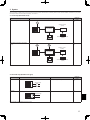
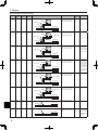
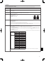
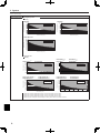
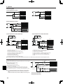
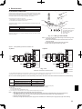


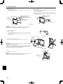
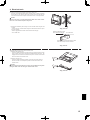
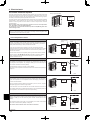
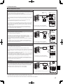
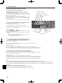
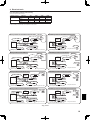

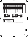

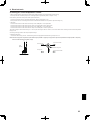
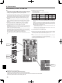
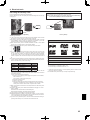


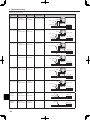


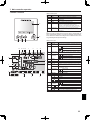
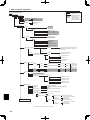

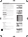

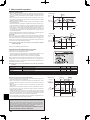


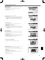

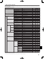
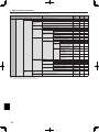
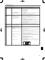
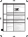

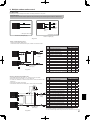
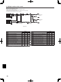

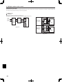
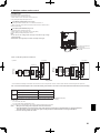
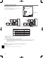
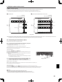
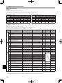

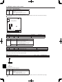

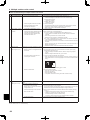

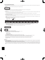


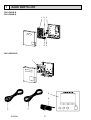
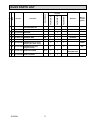


![[U4.84.02] Opérateur POST_DYNA_MODA_T](http://vs1.manualzilla.com/store/data/006361259_1-403116f6d656fa03c6cd8239831a974f-150x150.png)