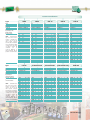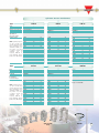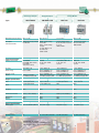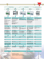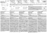
1
Carlo Gavazzi Creations:
Distinctive Features
As with all objects created by mankind, they can be
identified by qualities inspired by man, such as an
unmistakable genetic mark handed down by their creator.
Details: Every detail is conceived for providing
maximum efficiency and availability.
Performance: Skillful use of new technologies
makes a product offering more powerful and effective.
Passion: Attention to detail and meticulous work are
the distinguishing marks of people who love their
profession.
Design: For an instrument to be complete, it must
also be alluring, because beauty makes life more
exciting.
Details, performance, passion and design:
The unmistakable style of Carlo Gavazzi!
Innovation Always
WM3-96 introduces the modular
philosophy in the panel mounting
analysers.
0
0
20
year
EM4-DIN implements the modular
concept in the DIN-rail analysers and
energy meters.
year
2
0
20
WM5-96 adds to WM3 new advanced
control and data retransmission features.
year
5
0
20
CPT-DIN achieves a new dimension in the
world of 3-phase advanced power transducers.
year
6
0
20
EM24 DIN energy analyzer allows in the most
compact housing to measure up to 65A as a direct
connection. Its unique application oriented programming procedure allows an easy and fast installation.
year
6
0
20
EM26 96 with joystick and short cut display page selector
together with 2-colour back light alarm warning
revolutionises the panel mounting energy analyzer panorama.
year
7
0
20
EM21 72D the only combined meter in the market with detachable
display. One product, three installation modes: DIN-rail mounting energy
meter, panel mounting energy meter and transducer.
year
ROG400 the most integrated split-core active current sensor, represents the ideal
solution for retrofit applications.
8
0
20
What are and
Why use the Energy Management Components
Green levies, tighter operating margins and profits are
a few economic drivers forcing operators to use more
intelligent power management strategies. Real-time
measurements of electrical parameters, such as voltage
variations or distortions, can be transmitted via
networks to operators, warning of breaches in threshold
limits. And, the power quality information improves onsite efficiency and eases negotiation with utility
companies and energy authorities. For starters, several
utility meters or power analysers should be located at
the service entrance and at strategic points throughout
the site. Data can be transmitted to a host PC over a
serial link. Meanwhile, an energy management
software improves real-time data from several
networked nodes so to work out a power profile.
Large commercial or industrial electricity consumers
have to deal with fixed energy charges related to the
power demand of one or more sites as well as the charge
per unit of energy consumed. If the business exceed
4
the agreed power demand or “installed power” then it
is forced to pay extra costs. To make matters worse,
utilities can also impose higher installed power tariffs
that can often represent up to 60% of a commercial
consumer’s total utility charge. So clearly, a small
mistake that leads to a brief excess power demand
can cost many thousands of euro. Carlo Gavazzi
supplies Energy Management systems that provide
information so that operators can identify consumption
trends and take corrective actions. Analysing the power
profile operators can also aggregate loads and so
negotiate more favourable terms with the utility company.
Real time power consumption monitoring also allows a
site manager to anticipate overloads conditions that
would, for example, trip a circuit breaker. Alarm
thresholds can be set to warn managers if preset limits
are reached, and armed with the adequate system
loading and status information having time to organise
remedial actions.
Why different buses
and solutions
•
RS422-RS485 communication in a local
network: all the measurements made by single
instruments can be gathered through a standard
Modbus to a PLC or a PC in order to carry out
specific variable analysis and control (PowerSoft).
• Modem/RS232 communication: if the
measuring devices are spread in a wide area
or in different countries with the need to
collect the local data for centralised analysis,
the right answer is WM4 or PQT 90 with
external modem together with Wm4Soft or
PqtSoft software.
•
Web-server capability: if it is needed to read
the variables and download the logged data
exploiting the existing LAN, the solution is WM4
or PQT 90 with AR1060 plug-in module. It
easily displays the variables, the consumptions
and the trends in any enabled PC of the LAN,
(or connected to the internet) simply using a
browser.
•
Ethernet communication: all the data
acquired or stored by any instrument can easily
be trasmitted via Ethernet over the LAN (or
internet) to a Modbus TCP SCADA or
management software or PowerSoft. The
Ethernet port is on-board (WM5 or PQT H) or
available using an external accessory (VCP
DIN or SIU TCP).
•
Dupline communication: if the load
consumptions and alarms are to be monitored
together with a powerful building automation
system, the unique solution is called Carlo
Gavazzi Dupline installation bus. Everything
under control using only one bus system.
5
Energy Management and Dupline Field Bus . . .
making energy metering easy in very noisy plants
Du line
®
When an idea becomes a great idea …
The introduction of the Climate Change Levy (CCL) is
affecting consumers of energy in one way or another.
The basic outcome is that users who are inefficient in
their use of energy will pay more than efficient users.
There are several ways to avoid or reduce the extra
costs of the CCL but most of them involve some major
investments in plants or new technologies such as CHP,
wind power or other renewable energy sources. The
easiest way to offset these extra costs is to control your
consumption of energy.
The fundamental questions you have to ask
in order to find a solution to save energy
and money
• How much energy is consumed?
• Is there any energy waste?
… and the answers?
• Find an easy way to measure it
• For sure, there are loads that are running even
if it is not necessary. For instance, lights and
extractor fans when the building is empty.
Therefore a smart system to automatically turn
the loads ON and OFF is needed.
Fieldbus
The unlimited efficient solution possibilities
provided by the Dupline Field Bus
• Light control, switching ON/OFF and dimming lights.
• Temperature control, detecting signals from infrared
•
•
•
•
•
remote controls or PIR sensors and acting on heating
elements and/or valves.
Ventilation control, measure of room and outdoor
temperature.
Monitoring of doors, locks and windows.
Monitoring of fire alarms from smoke detectors.
Water leakage detection using proper sensors.
And many others …
Main application advantages
• Free topology for a fast, flexible
•
•
•
•
•
6
Installationbus
and easy to build
step-by-step installation; the system can be easily
adapted to new unexpected requirements.
User friendly: easy to code addresses and test, easily
accessible data from a PC/PLC.
High electrical noise immunity; no shielded cables
are needed, therefore existing cable/conduit/pipe
can be exploited.
Data communication up to 10 km; no signal repeaters
are needed.
Integration of the metering system with the Dupline
door-light-intrusion-remote controls and load switching.
Cost-effective solution when compared with the
ordinary systems.
Energy Management
The other Fieldbus
compatible instruments:
DIN-rail mounting: EM10, EM11,
EM3, EM4, EM21, EM23,
EM24, WM14, WM22,
CPT, PQT
Panel mounting:
EM21, EM26, WM3,
WM4, WM5, WM14.
The main Bus devices
Individual counter
G 4420 74014 inputs for: 4*kWh meters
2*kWh + 2*kvarh meters; reset feature;
data retention in case of power failure.
Master channel generator
G 3890 0014 G 3800 0015 Power supply:
115V, 230VAC or 10 to 30VDC.
The data acquisition system
Dupline DDE Server: to
acquire the information from
the Energy meters through
the Dupline field Bus system.
Displays and accessories
LCD text display, LED display,
coding units, repeater.
Bus-Powered Sensors
Inductive-magnetic proximity switches,
PIR-sensors, temperature sensors.
Analogue I/O Modules
1or 4*20mA/10VDC inputs,
1or 4*20mA/10VDC outputs.
Digital I/O Modules
1 to 8 contact inputs, 1 to 8
outputs, combined I/O modules.
Gateways and Interfaces
Profibus-DP, Devicenet, LonWork,
Interbus-S, ModBus.
PLC direct interfaces, Modem.
The new Dupline-Online M2M solution offers a complete
HW and SW package for automatic monitoring and
control of remote facilities via Internet or GSM.
7
The Energy Management components for . . .
Commercial Buildings:
Shopping Malls, Resorts,
Supermarkets, Restaurants
Lighting
Heating
Services and Infrastructures:
Conditioning
Alarms
Schools, Hospitals,
Stadiums
Billing
The Dupline
Solution
Commercial Buildings
8
In many commercial buildings as a matter of fact the need to
control and measure the energy consumption by single user
is becoming more and more important because of the need
to save money or issue the energy bill when needed.
Since the criterion is “the higher the energy consumption the
lower the price” instead of having a supply contract for
every shop/owner with a low consumption (higher energy
cost), there is only one contract with high consumption (lower
energy cost) whose sub-metering can be easily carried out
using our energy meters and power analysers.
Moreover the intelligent installationsbus Dupline can be
common to our energy metering system and our Building
Automation system. It allows, using proper Dupline sensors
(temperature, light) and I/O modules, to manage the lighting
system as well as the heating and air conditioning system so
to achieve further energy cost savings.
In the services and infrastructures, in addition to the building
automation system already mentioned above, there is also
the need to have a full electrical parameters control. In those
places the reliability of power supply and therefore the
safety conditions are of vital importance. Dupline can be
exploited to gather and manage the alarms coming from our
power analysers so to notify abnormal conditions in order to
let the maintenance personnel act in a due time.
Services and Infrastructures
Production Facilities:
Lighting
Cost Allocation
Heating
Ventilation
Light and Medium Industry:
Load Control
Cost
The Dupline
Solution
Since the cost pressure on
production is becoming higher
and higher, the energy
consumption measured by
type of production allows to
allocate and control the costs
in a proper and more accurate
way.
Our
Building
Automation
system based on Dupline bus
and relevant modules in
combination with our energy
metering system allows to
manage the lighting system as
well as other loads so to
achieve further energy cost
savings.
Production Facility
Light and Medium Industry
In the past just simple
measuring systems like currentvoltage-power and power
factor were available to keep
the mains under control. More
complex
solutions
were
available as well but in many
cases
requesting
higher
investments. Nowadays more
and
more
sophisticated
machines and loads like
computers,
switching-mode
power supplies and drives are
used in the production facilities
thus increasing significantly
the complexity of loads and of
problems. Carlo Gavazzi is
capable to provide different
levels of solution:
• WM12, a powerful
and
compact
unit
replacing the ordinary
set of three ammeters,
one voltmeter and one
rotary-switch.
• A more advanced
system which includes in addition to the power analysers
also a powerful supervision software with the aim to build-up
an installation and load history so to prevent with a planned
maintenance scheme load failures and production stops.
9
The Energy Management components for . . .
Big and Heavy Industry:
Steel, Shipyards, Mines,
Wood, Car Plants
Lighting
Heating
Transportation:
Ventilation
Airports
Alarms
The Dupline
Solution
In the big and heavy industry as well as in the airports it is
of fundamental importance to have a powerful control of the
mains since medium voltage systems and very high currents
are involved. Because of the type of loads, a low content of
harmonics is crucial to let the installation work in a proper
and reliable way. Stops of productions are not allowed at all
because they will significantly impact in the finance of the
company or service. Two levels of solutions can be provided:
• Power analysers with integrated harmonics analysis and a
supervision software with the aim to build-up an installation
and load history so to prevent with planned maintenance
load failures and production stops.
• Our intelligent installationsbus Dupline that, using proper
sensors (temperature, light) and I/O modules, can manage
the lighting system as well as the heating and air
conditioning system so to achieve energy cost savings. The
same bus is also used to gather and manage alarms coming
from our power analysers so to notify abnormal conditions
and react in a proper way.
10
Big and Heavy Industry / Transports
Water:
Drinkable Water Plants, Water Distribution
Plants
Pump
Level
Flow
Telecom:
Telecommunications
Alarms
The Dupline
Solution
A water treatment and
distribution system is very
hard to manage, because of
the dimensions of plants,
distances among the various
pumping
stations
and
parameters to be involved.
The Carlo Gavazzi Dupline
installationsbus with its up to
10 km transmission distance,
its free topology and the
variety of analogue and
digital
I/O
modules
is
capable to gather all the level,
flow and alarm signals and
the pumps start and stop in
order to manage the whole
system in a reliable and cost
effective way.
Last but not least, the
monitoring of mains and
working of pumps with local
power analysers and fully
integrated
data
logging
system is crucial to grant a
continuous load control that
with GSM modem and SMS
transmission capability, alerts
service staff on their mobile
phones as soon as an
abnormal condition occurs.
Water treatment and Distribution
Everybody knows how important
the mobile telecommunication is
nowadays and will be even
more in the future.
The relevant antennas are
installed in the field and have
to grant the communication
without problems.
Since field telecommunication
systems are not attended at
all, it is needed to provide to
the mobile phone company
information related to the
voltage, current, power and
in some cases also energy
consumptions.
Carlo Gavazzi is able, with
different levels of instrument
complexity, to provide the
requested electrical parameters
using, according to the
installation needs, compact or
modular power and enrgy
analysers.
Telecom
11
VMU-E
VMU-X
EM11 DIN
EM10 DIN
DC Energy Metering
AC Energy Metering
Gas and Water Metering
Multi Function Metering
Variables Analysis
Power Quality Analysis
CT connections
Direct high-current connections
Modular housing
Graphic Display
Digital Inputs
Pulse Outputs
Analogue Outputs
Alarm Outputs
Serial Communication
Profibus DP
Internet-Ethernet Communication
GSM/SMS Management
Dupline
Optical communication port
12
EM23 DIN
EM4 DIN
EM3 DIN
EM21 72D
EM24 DIN
WM12 96
WM12 DIN
EM26 96
WM10 DIN
WM22 DIN
WM14 96
WM14 DIN
WM4 96
WM3 96
CVT DIN
CPT DIN
WM5 96
PQT H
PQT 90
*
* WM5-96 only
13
The Features and Benefits for today’s and tomorrow’s demands
EM24 DIN
Tamper proof and revenue approval for billing purpose
Tamper proof capability using proper covers thus
protecting all inputs/outputs screw terminals.
Lockable programming access using a password and a
seal on the front selector.
EM24 DIN, EM26 96
PowerSoft
Easy variables scrolling
by means of the front joystick.
Time saving installation system
using self-power supply and
automatic phase detection.
Direct variable page access
by means of the front fourposition selector programmable
by the user.
The Energy Manager
Energy, gas and
water consumption
analysis, also by
multi-tariff, so to
have a statistical
basis either to
renegotiate
the
contract or to
choose a cheaper supplier. All meter-variables
control and anomaly logging by activating also
hardware alarms and sending out e-mails to
automatically alert the maintenance staff. LAN or
Internet variables information spread simply using
the standard browser of any PC.
Application oriented programming structure
Selection of eight different applications like:
Basic domestic - Shopping malls - Advanced domestic
- Multi domestic (also camping and marinas) - Solar Industrial - Advanced industrial - Advanced industrial
for power generation, providing only the needed
programming parameters and the display variables
thus simplifying the installation and the display
readout.
EM11 DIN
Power analyzer features into an ultra
compact energy meter
New solution providing a full
parameters control, saving also
space in the small switch panels.
Relay output to switch OFF a non
priority load thus preventing a
line overload condition.
14
AR1060 Module
Web-server capability on board
of WM4 and PQT 90
Module to easily read
through the LAN or the
WEB the instantaneous
variables, energy, water
and gas being measured.
Logged variables downloadable and displayable
to evaluate parameters, consumption trends and
related costs helping the users to plan a proper
maintenance and to achieve cost reductions where
possible.
EM24 DIN, EM3 DIN, EM4 DIN, WM22 DIN
VMU-E, VMU-X
65A and 100A available
Connections for cables
with cross-section area
from 6 to 35mm2 instead
of
passing-by
types
assuring a “contactor
type”
wiring
and
connection protection.
Modular DC energy analyzer with
built-in 6 digit display. The
analyzer is the combination of
two modules where VMU-E is
the metering unit while VMU-X
is the universal power supply
unit, according to the model
can become also a digital
output or an RS485 port.
WM22 DIN
EM21 72D
All information available at a glance
Example of variables
displayed with serial
communication
diagnostics: r.t (Rx/Tx).
One product, 3 different installation modes
Detachable display to carry out up to 3 installation
modes from the same instrument: DIN-rail, panel
mounting or transducer.
DIN-rail mounting
Example of 7 1/2 digit
energy displaying.
Transducer
1 +1 = 3
Panel
Mounting
WM5 96
Easy infrared communication
Front optical port for an
easy
and
fast
communication with a PC
or a laptop without the
need to open the switchgear where the instrument is installed, granting the
highest safety level for the user. Availability of
additional functions through the optical port like
the instrument programming, the measured data
and logged events reading.
Software as programming tools
for CPT, PQT, WM4, WM5, WM14, EM21, EM24 and EM26
Tools allowing the user to
configure the instruments
using the PC and the
RS485, the RS232, or the
optical (WM5 and PQT
H only) ports, making the
programming job easier
and faster.
15
A new concept of Modularity
In addition to the obvious need to improve the
performances of the measuring instruments in order to
keep them up-to-date with the state-of-the-art
technology, it is more and more important to offer userfriendly instruments being easily and quickly
adaptable to the applications and management needs
of the customers.
These needs resulted in a new and modern range of
instruments which, according to various criteria of
signal processing and displaying, can be
turned into:
• transducers (only 96 series)
• indicators
• controllers
16
Technical Advantages
and Cost Benefits
•
•
•
•
PLUG and PLAY modules common to all models;
maximum in-field flexibility.
Possibility to expand the number and the kind of
outputs according to new application needs without
replacement of the instruments in-field.
Small number of models in-house, with a high offer
of possible combinations at the same time.
Investments in the instrumentation only limited to
the present needs with the possibility to expand it
in the future for any additional requirements.
17
Communication Adaptor
Types
Description
SIU-PC2
RS422/RS485 to RS232
converter
Front: 100x67mm
RS232
9-pole, female
1-DCD, 2-TxD, 3-RxD, 4-DSR
5-GND, 6-DTR, 7-CTS, 8-RTS
RS422, RS485
2-wire and 4-wire
communication
SIU-PC3
SIU-TCP
VCP-DIN
RS422/RS485 to USB
converter
Front: 60x37,5mm
USB type A
Ethernet to RS232/485
Modbus Gateway
Front: 100x67mm
Ethernet, 10/100Mbps
RJ45
Ethernet serial device
server
Front: 100x67mm
Ethernet, 10/100Mbps
RJ45
RS422, RS485
2-wire communication
RS232, RS485
2-wire communication
RS232, RS422, RS485
2-wire communication (with
automatic data directional
control)
NO
NO
Screw terminal block
(with adapter)
Max 921.6 kBaud
Port 1/Port 2
Power-on, Tx, Rx
NO
NO
9 pole, male
Max 230.4 kBaud
LAN/serial
Power on, link, ready
NO
NO
9 pole, female
Max 230.4 kBaud
LAN/serial
Power on, link, ready
Port1/Port2: 2kV (option I)
Port1/Port2 and
power supply: 2kV (option I)
-20 to +60 °C
(R.H. 90% to 95% N.C.)
-20 to +85 °C
(R.H. 90% to 95% N.C.)
DIN-rail mounting kit, wiring
diagrams
Port1/Porta: not insulated
LAN/serial: 1.5kV
LAN/serial: 1.5kV
0 to +55 °C
(R.H. 5% to 95% N.C.)
-20 to +70 °C
(R.H. 5% to 95% N.C.)
screw/ 9-pole connector
adapter
0 to +55 °C
(R.H. 90% to 95% N.C.)
-20 to +85 °C
(R.H. 90% to 95% N.C.)
DIN-rail mounting kit,
9-pole serial cable, power
supply adapter, software,
quick guide
Other characteristics
ESD protection for serial
signals: 15kV;
power reverse protection;
wall mountable;
reverse conversion capability
Self power supply from USB.
ESD protection for serial
signals: 15kV.
ESD protection for serial
signals: 15kV;
wall mountable;
reverse conversion capability
UK and US versions available
0 to +55 °C
(R.H. 90% to 95% N.C.)
-20 to +85 °C
(R.H. 90% to 95% N.C.)
DIN-rail mounting kit,
9-pole serial cable, power
supply adaptor, null modem
9-pole adaptor, software,
quick guide
ESD protection for serial
signals: 15kV;
wall mountable;
reverse conversion capability
UK and US versions available
Power supply input
12 to 30 VDC
Suggested adapter:
SPD12-101 (120 to 240VAC/DC)
CE, FCC
IP30
9 to 30 VDC. VAC adapter
included (100 to 240 VAC).
US, Euro plugs incl.
CE, cULus, TÜV
IP30
9 to 30 VDC
VAC adapter included
230VAC (115VAC US vers.)
CE, UL, FCC
IP30
Housing
Port 1
Connections
PIN assignement
Port 2
RS485 working mode
Line Bias
Line termination
Connections
Baud rate
Protection
Indication
(by means of LEDs)
Insulation
Operating temperature
Storage temperature
Included set
Approvals
Protection degree
18
NO
NO
Screw terminal block
Max 230.4 kBaud
Port 1/Port 2/Power supply
Power-on, Tx, Rx
CE, FCC
IP30
EM10 DIN EM11 DIN
EM10 DIN is a simple energy meter while EM11 DIN is an
ultra compact Energy Analyzer for one-phase systems
which introduces, first in the market, the basic features of a
power analyzer into an energy meter for one-phase
applications.
Certifications on request:
• EC Type examination, Annex B of MID (option"P")
• MID Annex B+F (option "PF") for legal metrology
Housing (H x W x D)
Display type Var. on display
Instantaneous variables
Energy variables
Accuracy
Temp. drift Refresh rate
System type
Voltage inputs (Un)
Current inputs (Ib/Imax)
Digital inputs
Primary of CT/ VT
Measurements:
EM10 Variables
EM11 Variables
Harmonic distortion
Outputs:
Pulse
Alarm
Analogue
Serial
Digital filter
Other characteristics
Approvals
Power supply
Protection degree
90x18x67mm (1-DIN module)
LCD, h: 7mm YES
4 DGT (only EM11-DIN)
5 + 1 DGTs
W-PF:±(1% RDG+2DGT)
var:±(2% RDG+2DGT)
VLN-A:±(0.5% RDG+2DGT)
Class 1 (kWh) EN62053-21
Class B (kWh) EN50470-3
Class 2 (kvarh) EN62053-23
≤200ppm/°C 1.5 times / s
1-phase
230VAC
Ib: 5A, Imax: 32AAC
N.A.
N.A.
TRMS method.
kWh
VLN, A, Hz, W, Wdmd, var, PF, kWh, kvarh
N.A.
1 (open collector), 1000imp/kWh
1 (relay) only EM11-DIN
N.A.
N.A.
N.A.
Load controller (on kW) in case of
over power or other alarm to be set on
any available variable
Start-up current: 20mAACCE,
CE, MID certification on request
Self power supply
IP40
The main advantages
• Better variable readability thanks to a wide LCD display.
Only EM11-DIN:
• Not only the usual active and reactive energy
consumption information but also the status of the power
supply giving to the user an overview of all the electrical
parameters.
• Active power alarm notifying an overload condition by
means of an internal buzzer.
• Variable control with alarm activation on any available
variable
• Switching off a non priority load (with a relay output) thus
preventing an overload condition and avoiding the trip of
the overload protection downstream the official watt-hour
meter.
The best to suit your needs!
MID certified for
legal metrology
(on request)
Performances
Energy meter EM10 DIN
Energy Analyzer EM11 DIN
Hardware
Functions
In-Out
Comm
19
EM3 DIN
EM3 DIN is an energy meter that has been developed to
meet the requirements of those applications where a very
simple and reliable instrument is needed.
The main advantages
• Electromechanical display allowing the user to read the
consumed energy even when the load or the meter is not
power supplied.
Housing (H x W x D)
Display type
Variables on display
Instantaneous variables
Energy variables
Accuracy
Temperature drift
Refresh Rate
System type
Voltage inputs (Un)
Current inputs (Ib/Imax)
Digital inputs
Primary of CT/VT
Measurements:
Variables
Harmonic distortion
Outputs:
Pulse
Alarm
Analogue
Serial
Digital filter
Other characteristics
Power supply
Approvals
Protection degree
90x162.5x63mm (9-DIN modules)
Mechanical
YES
N.A.
6+1 DGT
Class 2 (EN61036)
Class 3 (EN61268)
≤250ppm/°C
N.A.
Unbalanced: 3-phase
120/208VAC, 230/400VAC, 380/660VAC
Ib: 20A, Imax: 100AAC
N.A.
N.A.
TRMS method
kWh or kvarh (selectable)
N.A.
2 (open collector type)
N.A.
N.A.
N.A.
N.A.
Start-up current: 80mAAC
Self power supply, 115VAC, 230VAC
CE
IP40
• Easy installation avoiding any programming set-up.
• Self power supply making the installation easier and
quicker.
• Direct connection up to 100A allowing the user to save
the costs of external current transformers and of
relevant wiring.
• Dual pulse output transmitting to a PLC or other
equipment
the
active
and
reactive
energy
simultaneously.
• Wall mounting avoiding any other protection enclosure.
The best to suit your needs!
connection
100A direct
available.
Performances
Modular Energy Meter EM3 DIN
100A
Hardware
20
Functions
In-Out
Comm
EM4 DIN
EM4 DIN is an advanced utility meter capable to measure not
only the usual consumed energies but also gas and water by
means of the optional dual contact inputs module.
The main advantages
• High accuracy and resolution for a fine cost calculation.
• Simultaneous indication of both active and reactive energy
allowing the user to read the variables at a glance.
Housing (H x W x D)
Display type
Variables on display
Instantaneous variables
Energy variables
Accuracy
Temperature drift
Refresh rate
System type
Voltage inputs (Un)
Current inputs (In/Ib/Imax)
Digital inputs
Primary of CT/VT
Measurements:
Variables
Harmonic distortion
Outputs:
Pulse
Alarm
Analogue
Serial
Dupline
Digital filter
Other characteristics
Power supply
Approvals
Protection degree
90x162.5x63 (9-DIN modules)
LCD (back lighted), h: 8.5mm
YES
3 /2 DGTs
8 DGTs + 7 /2 DGTs
Class 1 (EN61036)
Class 2 (EN61268)
VLN-A:±(0.5% RDG+2DGT)
≤200ppm°/C
2 times/s
Unbalanced: 3-phase
57/100V, 120/208V, 230/400V,
380/660VAC
In: 5A, Imax: 10AAC
Ib: 20A, Imax: 100AAC
2 independent (H2O/gas counter or
4-time period selection)
Prog: CT up to 5,000A; VT up to 200kV
TRMS method
Total: kWh, kvarh, H2O, gas;
t1-t2-t3-t4:
kWh, kvarh;
t1-t2: gas; WL1, WL2,WL3, Wdmd
N.A.
2 (open collector type)
1 (open collector or relay)
N.A.
RS422/485 (Modbus)
kWh and kvarh data transmission,
water (hot - cold) and gas inputs and
relevant data transmission
N.A.
Modular concept, plug-in modules
Self power supply, 24, 48, 115, 230VAC;
18 to 60VDC, 73 to 143VDC
CE
IP40
1
1
• Displaying of the active power demand with manual or
external synchronisation. The fixed power supply costs are
calculated with the same system used by the electricity
board.
• Management of the pulses from gas and water meters
based on single or dual tariff calculation and energy multitariff management (by means of two selection contact
inputs) giving more flexibility and meeting the application needs.
• Metering of energy, water and gas in the same instrument
allowing the data transmission by means of the same
communication port. Now available also via Dupline.
• Effective control of phase sequence, serial communication
and wrong connection of the current inputs statuts making
the instrument installation: easy, fast and free of wiring errors.
• Self power supply working even in case of one phase
line failure granting continuous metering of energy.
The best to suit your needs!
connection
100A direct
available.
Performances
Modular Utility Meter EM4 DIN
100A
Hardware
Functions
In-Out
Comm
21
EM21 72D
EM21-72D is an innovative, cost-effective and compact
energy meter: it is the first on the market to have a
detachable display allowing it to be mounted either on a
panel with just 72x72 mm or on a DIN-rail in only 4
modules with neither any adaptor or external accessory.
Certifications on request:
• EC Type examination, Annex B of MID (option"P")
• MID Annex B+F (option "PF") for legal metrology
DIN-rail mounting
Transducer
1 +1 = 3
Panel
Mounting
Energy Meter EM21 72D
72x72x65mm (4-DIN modules)
2 lines LCD, h: 7mm
YES
3x3 DGTs
6+1 DGTs
Class 1 (kWh) EN62053-21
Class B (kWh) EN50470-3
Class 2 (kvarh) EN62053-23
VLN-A:±(0.5% RDG+2DGT)
Temperature drift
Refresh rate
System type
Voltage inputs (Un)
Current inputs (In/Imax)
≤200ppm/°C
1s
3-phase + neutral
120/230VAC, 400VAC
In: 5AAC;
Imax: 6AAC
N.A.
Digital inputs
Primary of CT/VT
Measurements:
Variables
Prog: CT up to 60k; VT up to 6.00k
TRMS method
Sys: W, var, PF, Phase-sequence, Hz. kWh, kvarh.
Single-phase: VLL, VLN, A, PF.
Harmonic distortion
Outputs:
Pulse
Alarm
Analogue
Serial
Digital filter
Other characteristics
Power supply
Approvals
Protection degree
N.A.
1 (static opto-mosfet)
N.A.
N.A.
RS485 (2-wire, Modbus)
N.A.
Phase sequence indication and control
Self power supply
CE, cULus, MID certification on request
IP50
22
The best to suit your needs!
MID certified for
legal metrology
(on request)
Performances
Housing (H x W x D)
Display type
Variables on display
Instantaneous variables
Energy variables
Accuracy
The main advantages:
• Detachable display allowing three installation modes:
DIN-rail energy meter, panel mounting energy meter and
transducer.
• Space saving on panel boards by means of its compact
housing.
• Energy measurement fulfilling both the new European
standard EN50470-3 and the international standards
IEC62053-21 and IEC62053-23.
• Time saving installation system exploiting self-power
supply, automatic phase detection and application
oriented programming procedure.
• Pulsing output for easy and quick data transmission to
PC/PLC for full load control.
• RS485 communication port for full BMS integration.
Hardware
Functions
In-Out
Comm
EM23 DIN
EM23-DIN is a very simple, compact and easy-to-install
energy meter, the most compact on the market allowing a
3-phase direct connection up to 65A.
Energy Meter EM23 DIN
Housing (H x W x D)
Display type
Variables on display
Instantaneous variables
Energy variables
Accuracy
71x90x65mm (4-DIN modules)
LCD, h: 9mm
YES
2 lines 1x7 DGTs; 3x3 DGTs
6+1 DGTs
Class 1 (kWh) EN62053-21
Class B (kWh) EN50470-3
Class 2 (kvarh) EN62053-23
VLN-A:±(0.5% RDG+2DGT)
Temperature drift
Refresh rate
System type
Voltage inputs (Un)
Current inputs (Ib/Imax)
Digital inputs
≤200ppm/°C
750 ms
3-phase
400VAC
Ib: 10A, Imax: 65AAC
N.A.
Primary of CT/VT
Measurements:
Variables
N.A.
TRMS method
Sys: W, var;
single-phase: A
kWh, kvarh
Harmonic distortion
Outputs:
Pulse
Alarm
Analogue
Serial
Digital filter
Other characteristics
Power supply
Approvals
Protection degree
N.A.
1 (open collector)
N.A.
N.A.
N.A.
N.A.
Phase sequence indication
Self power supply
CE, MID certification on request
IP50
Some benefits are:
• Compact size, only 4-DIN modules, for space saving
also in panel boards.
• Direct connection up to 65 A to save the cost of three
external current transformers.
• Energy measurement fulfilling both the new European
standard EN50470-3 and the international standards
IEC62053-21 and IEC62053-23.
• Displaying of the system active and reactive power and
single phase currents for an immediate consumption
analysis.
• No programming required and warning message in case
of reverse phase sequence, for an easy and fast
installation.
• Pulsing output for an easy and quick energy
retransmission to a PLC for a load priority management
program.
The best to suit your needs!
MID certified for
legal metrology
(on request)
Performances
Certifications on request:
• EC Type examination, Annex B of MID (option"P")
• MID Annex B+F (option "PF") for legal metrology
Hardware
Functions
In-Out
Comm
23
EM24 DIN
Certifications on request:
• EC Type examination, Annex B of MID (option"P")
• MID Annex B+F (option "PF") for legal metrology
Energy Analyzer EM24 DIN
Housing (H x W x D)
Display type
Variables on display
Instantaneous variables
Energy variables
Accuracy
Temperature drift
Refresh rate
System type
Voltage inputs (Un)
Current inputs (In/Ib/Imax)
Digital inputs
Primary of CT/VT
Measurements:
Variables
Harmonic distortion
Outputs:
Pulse
Alarm
Analogue
Serial
Dupline
Digital filter
Other characteristics
Power supply
Approvals
Protection degree
24
90x71x65mm (4-DIN modules)
LCD (STN technology), h: 7mm
YES
3x4 DGTs
8 DGTs
W-VA-PF:±(1% RDG+2DGT)
var:±(2% RDG+2DGT)
VLN-A:±(0.5% RDG+1DGT)
VLL:±(1% RDG+1DGT)
Class 1 (kWh) EN62053-21/B EN50470-3
Class 2 (kvarh) EN62053-23
≤200ppm/°C
1.5 times / s
Unbalanced: 2-3-phase; bal.:1-3-ph.
120/208VAC, 400VAC
In: 1/5A, Imax: 10AAC;
Ib: 10A, Imax: 65AAC
3 independent (H2O/gas counter or
4-time period selection)
Prog: CT up to 60k; VT up to 6000
TRMS method
Sys: VLL, VLN, Admd max, var, VA, Wdmd, Wdmd max,
VAdmd, VAdmd max, Hz. kWh, kvarh, h.
Single-phase: VLL, VLN, A, W, var, VA, PF,
kWh, kvarh
N.A.
2 (open collector or relay)
2 (open collector or relay)
N.A.
RS485 (2-wire, Modbus)
6 counters, 8 instantaneous variables,
2 alarms, 1 digital input
Action: on variables and outputs
Phase sequence indication and control
Self power sup., 18 to 60VAC/DC,
115/230VAC according to the model
CE, MID certification on request
IP40
EM24 DIN can also be panel
mounted by means of the front
adaptor “4DIN96 Adapter”.
The main advantages:
• Space saving on panel boards by means of its compact
housing.
• Wide angle variable readability by means of a sharp LCD
display (STN technology).
• Energy measurements fulfilling both the new European
standards EN50470-3 and the international standard
IEC62053-23.
• Gas, hot-water, cold-water and remote heating
measurements thanks to its three digital inputs.
• Extended energy measurements using total/partial or
total/multi-tariff metering.
• Money saving by means of the integrated current
transformers allowing to measure currents up to 65A.
• Extended alarm control on any available variable by
means of up to two digital outputs.
• Time saving installation system using self-power supply,
automatic phase detection and application oriented
programming structure.
• Easy variable scrolling by means of the front joystick.
• Wide interfacing capability using up to 2 pulse outputs or
the RS485 communication port.
The best to suit your needs!
MID certified for
legal metrology
(on request)
Performances
EM24 DIN is a compact Energy Analyzer for three phase
unbalanced systems. This new meter is capable to
measure in the most compact housing not only the
traditional active and reactive energies but also gas, hotwater, cold-water and remote heating consumptions.
Hardware
Functions
In-Out
Comm
EM26 96
Certifications on request:
• EC Type examination, Annex B of MID (option"P")
• MID Annex B+F (option "PF") for legal metrology
Energy Analyzer EM26 96
Housing (H x W x D)
Display type
Variables on display
Instantaneous variables
Energy variables
Accuracy
Temperature drift
Refresh rate
System type
Voltage inputs (Un)
Current inputs (In/Imax)
Digital inputs
Primary of CT/VT
Measurements:
Variables
Harmonic distortion
Outputs:
Pulse
Alarm
Analogue
Serial
Digital filter
Other characteristics
Power supply
Approvals
Protection degree
96x96x61.4mm
LCD (2-colour with back light STN
technology), h: 9.5mm
YES
3x4 DGTs
8 DGTs
W-VA-PF: ±(1% RDG+2DGT)
var: ±(2% RDG+2DGT)
VLN-A: ±(0.5% RDG+1DGT)
VLL: ±(1.5% RDG+1DGT)
THD: ±(2% RDG+1DGT)
Class 1 (kWh) EN62053-21/B EN50470-3
Class 2 (kvarh) EN62053-23
≤200ppm/°C
1.5 times/s
Unbalanced: 2-3-phase; bal.:1-3-ph.
120/208VAC, 400/660VAC
In: 1/5A, Imax: 10AAC
3 independent (H2O/gas counter or
4-time period selection)
Prog: CT up to 60k; VT up to 6000
TRMS method
Sys: VLL, VLN, An, Admd max, var, VA, Wdmd,
Wdmd max, VAdmd, VAdmd max, Hz. kWh, kvarh, h.
Single-phase: VLL, VLN, A, W, var, VA, PF,
%THD-V, %THD-A, kWh, kvarh
THD up to 15th H (V and A)
3-open collector or 2-relay
3-open collector or 2-relay
N.A.
RS485 (2-wire, Modbus)
Action: on variables and outputs
Phase sequence indication and control
18 to 60VAC/DC, 90 to 260VAC/DC
CE, cULus, MID certification on request
IP50
The main advantages:
• Suitable to be mounted on any switch or control-gear by
means of only 46 mm housing behind the panel.
• Wide angle variable readability by means of a sharp and
two colour back lighted LCD display (STN technology).
• Better and more reliable energy measurements fulfilling
both the new European standards EN50470-3 and
EN62053-23.
• Gas, hot-water, cold-water and remote heating
measurements thanks to its three digital inputs.
• Extended energy measurements using total/partial or
total/multi-tariff metering.
• Extended alarm control on any available variable by
means of up to three digital outputs with display warning
based on back light colour changing.
• Load failure prevention thanks to the harmonic analysis
and control.
• Easy programming using the application oriented
programming structure.
• Easy variable scrolling by means of the front joystick.
• Wide interfacing capability using up to 3 pulse outputs or
the RS485 communication port.
The best to suit your needs!
MID certified for
legal metrology
(on request)
Performances
EM26 96 is a panel mounting Energy Analyzer for three
phase unbalanced systems capable to perform not only an
extended consumption analysis but also keeping under
control all the electrical parameters, Harmonics included.
Hardware
Functions
In-Out
Comm
25
WM10 DIN
WM10-DIN is a 3-phase multifunction meter simple, easyto-install and extremely compact, allowing a direct
connection up to 65A in only 4-DIN modules. It measures
and monitors all the parameters of an electrical installation,
line or load.
Housing (H x W x D)
Display type
Variables on display
Instantaneous variables
Energy variables
Accuracy
Temperature drift
Refresh rate
System type
Voltage inputs (Un)
Current inputs (Ib/Imax)
Digital inputs
Primary of CT/VT
Measurements:
Variables
Harmonic distortion
Outputs:
Pulse
Alarm
Analogue
Serial
Digital filter
Other characteristics
Power supply
Approvals
Protection degree
71x90x65mm (4-DIN modules)
LCD, h: 9mm
YES
2 lines, 3x3 DGTs
N.A.
0.5% RDG (voltage/current)
≤200ppm/°C
750 ms
3-phase
400VAC
Ib: 10A, Imax: 65AAC
N.A.
N.A.
TRMS method
Sys: W, var, PF, Hz.
Single-phase: A, VLN, VLL, W, var.
N.A.
N.A.
N.A.
N.A.
N.A.
N.A.
Phase sequence indication
Self power supply
CE
IP50
The main advantages:
• Space saving on panel boards.
• The three external current transformers are not needed
because of the high-current direct connection.
• Measurement of the main system and single phase
variables to perform a full load control.
• Time saving installation system (just connect it, and it
measures) and no programming required.
The best to suit your needs!
Performances
Multifunction meter WM10 DIN
Hardware
26
Functions
In-Out
Comm
WM12 96
WM12 DIN
WM12 DIN and WM12 96 are general purpose multi
function meters that allow to monitor all the mains
parameters of an electrical line or load. The compact
housings combined with a complete selection of
measurements allow the instruments to be mounted in all
the switch and control gears as local indicators, instead of
the classical single function analogue or digital panel
meters.
Multifunction Meters WM12 DIN WM12 96
Display type
Variables on display
Instantaneous variables
Energy variables
Accuracy
Temperature drift
Refresh rate
System type
Voltage inputs (Un)
Current inputs (In)
Primary of CT/VT
Measurements:
Variables
Harmonic distortion
Outputs:
Pulse
Alarm
Analogue
Serial
Digital filter
Other characteristics
Power supply
Approvals
Protection degree
90x107.5x64.5mm (6-DIN mod.) (WM12 DIN)
96x96x61.5mm (WM12 96)
LED, h: 14mm
YES
3 DGTs
N.A.
W-VA:±(1% F.S.+1DGT)
var:±(2% F.S. +1DGT)
VLL: ±(1.5% F.S. +1DGT)
VLN-A:±(0.5% F.S. +1DGT)
≤200ppm/°C
1.5 times / s
Unbalanced: 1-2-3-phase
100/208VAC, 400/660VAC
5AAC
Shunts (not insulated inputs)
Prog.: CT up to 5,000A; VT up to 10kV
TRMS method
Sys: VLL, An, W, var, VA, Wdmd, Wdmd peak, VAdmd, Hz
Single-phase: VLL, VLN, A, W, var, VA, PF
N.A.
N.A.
N.A.
N.A.
RS422/485 (Modbus)
Action: on variables and outputs
Over neutral current and under/over
voltage indication (warning signal)
24, 48,115, 230VAC; 18 to 60VDC
CE, cURus, cCSAus (only WM12 96)
IP40 (WM12 DIN); IP65 (WM12 96)
NEMA4x, NEMA12
The unit is provided with some unique installation visual
status functions like:
• The window control of the mains 3-phase voltage
notifying the user, at a glance, if the mains is supplied
out of the requested power supply tolerance.
• The neutral current control showing immediately any load
or installation anomaly, due to high harmonic distortion
or load insulation loss (high earth leakage current).
The best to suit your needs!
Performances
Housing (H x W x D)
(Virtual)
96
DIN
Hardware
Functions
In-Out
Comm
27
WM14 96
WM14 DIN
WM14 DIN and WM14 96 available as Basic and Advanced
power analyzers can be used in all the applications where it
is needed to measure and control the main electrical
parameters and to transmit them by pulses, by serial
communication or Profibus DP to a PLC or a PC. WM14 is
compact and is available either for panel mounting or DINrail mounting.
Power Analyzers WM14 DIN WM14 96
Basic and Advanced functions
Housing (H x W x D)
Display type
Variables on display
Instantaneous variables
Energy variables
Hours
Accuracy
Temperature drift
Refresh rate
System type
Voltage inputs (Un)
Current inputs (In)
Primary of CT/VT
Measurements:
Variables
Harmonic distortion
Outputs:
Pulse
Alarm
Analogue
Serial
Digital filter
Other characteristics
Power supply
Approvals
Protection degree
90x107.5x64.5mm (WM14 DIN) (6-DIN mod.)
96x96x61.5mm (WM14 96)
LED, h: 14mm
YES
3 DGTs
8+1 DGTs
5+2 DGTs
W-VA:±(1% F.S.+1DGT)
var:±(2% F.S. +1DGT)
VLL: ±(1.5% F.S. +1DGT)
VLN-A:±(0.5% F.S. +1DGT)
kWh: cl. 1(Adv), 2(Bas); kvarh: cl. 2(Adv), 3(Bas)
≤200ppm/°C
1.5 times/s
Unbalanced: 2-3-phase; bal.: 1-3-ph.
100/208VAC; 400/660VAC
5AAC; Basic: shunts or CT’s depending
on the model. Advanced: shunts
Prog.: CT up to 5,000A; VT up to 10kV
TRMS method
Sys: VLL, An, W, var, VA, Wdmd,Wdmd max, VAdmd, Hz
Wh, varh, h. Single-phase: VLL, VLN, A,
W, var, VA, PF, Admd, Admd max
THD up to the 16th harmonics (V and A)
2 (open collector)
16 with OR/AND function (2 relays)
N.A.
RS422/485 (Modbus), Profibus DP V0
Action: on variables and outputs
Basic version: with Profibus on request
Adv. vers.: with pulses or alarms on req.
Basic: 24, 48,115, 230VAC;
Adv.: 18 to 60VAC/DC, 90 to 260VAC/DC
CE, cURus, cCSAus
IP40 (WM14 DIN); IP65 (WM14 96)
NEMA4x, NEMA12
multi function meter providing the following additional
features and benefits:
• Metering of both total and partial active and reactive
energies with pulse outputs in order to survey not only
the typical load parameters but also the consumptions.
• Measurement of the thermal current, by single phase,
and recording of the maximum demands. This
information will let the maintenance people know if the
over current protections (fuses, automatic switches,
etc.) are adequately preset and in case of trip which is
their real current.
• Hour counter meter function. On board of a machine or
a generating-set, the instrument shows how long those
machines are being used saving also the cost of an
external classical hour counter meter. A proper
“machine usage” cost and/or mechanical maintenance
can be estimated and planned.
• OR/AND control of up to 16 selected variables so to grant
an extended load or line control through 2 digital outputs.
The best to suit your needs!
Performances
WM14 is the natural evolution of WM12. It maintains the
same advantages and measurement capabilities of the
• Basic version only
• Insulated current inputs
• Universal AC/DC power supply.
OR
AND
16
96
DIN
Hardware
Functions
In-Out
Comm
The histogram is related to the “Advanced” version.
28
WM22 DIN
WM22 DIN is a modular power analyzer that allows to
monitor all the mains parameters of an electrical line or
load and to control one of them. The amazing design of the
housing combined with outstanding performances makes
WM22 DIN an instrument to be used in all the applications
up to 5000A and up to 200kVLL.
The remarkable features of WM22 DIN
• Direct measurement of up to 100A: no external current
transformer needed.
Housing (H x W x D)
Display type
Variables on display
Instantaneous variables
Energy variables
Accuracy
Temperature drift
Refresh rate
System type
Voltage inputs (Un)
Current inputs (In/Ib/Imax)
Digital inputs
Primary of CT/VT
Measurements:
Variables
Harmonic distortion
Outputs:
Pulse
Alarm
Analogue
Serial
Dupline
Digital filter
Other characteristics
Power supply
Approvals
Protection degree
90x162.5x63mm (9-DIN modules)
LCD (back lighted), h: 8.5mm
YES
4x3 /2 DGTs
7 /2 DGTs
V -A:±(0.5 RDG+1DGT)
W-VA:±(1% RDG+1DGT)
Class 1 (EN61036)
Class 2 (EN61268)
≤200ppm/°C
2 times/s
Unbalanced: 3-phase
57/100VAC, 120/208VAC,
230/400VAC, 380/660VAC
In: 5A, Imax: 10AAC
Ib: 20A, Imax 100AAC
N.A.
Prog.: CT up to 5,000A; VT up to 200kV
TRMS method
Sys: VLL, W, var, VA, Wdmd, VAdmd, PF, Hz, total
Wh, total varh, partial Wh, partial varh.
Single-phase: VLN, A, W, var, VA, PF, THD.
THD up to the 7th H (V and A)
2 (open collector)
1 (open collector or relay)
1 (20mADC, 10VDC)
RS422/485 (Modbus)
kWh and kvarh data transmission,
water and gas inputs and relevant
data transmission
Action: on variables and outputs
Modular concept, plug-in modules,
phase asymmetry control
Self power supply, 24, 48, 115, 230VAC;
18 to 60 VDC, 73 to 143 VDC
CE
IP40
1
1
LN
• Simultaneous display of four variables: information
available at a glance.
• A full range of measurements available: everything
under control.
• Plug and play output modules: easy interfacing to
external devices.
The main advantages
• Total harmonic analysis of both current and voltage
notifying potential load failures.
• Phase asymmetry control notifying line failures.
• Dual pulse output, analogue output, RS485 or Dupline port
providing the communication to PLC’s, to PC’s and to
Dupline building automation system.
• Serial communication and wrong connection of the current
input status indications making the instrument installation
easy, fast and out of wiring errors.
• Self power supply working even in case of one phase line
failure granting the measurement of all the variables all
the time.
The best to suit your needs!
connection
100A direct
available.
Performances
Modular Power Analyzer WM22 DIN
100A
Hardware
Functions
In-Out
Comm
29
WM3 96
WM3 96 is a modular analyzer of power quality that,
thanks to a 32-bit μ-Processor, allows the operator to
continuously and completely monitor the mains. All
measurements with a direct connection up to 830VAC
(phase-phase), up to 600kV (VT connection) and up to
30kA (CT connection) allow the operator to use WM3 96 in
any kind of installation. WM3 96 is a flexible and a
powerful instrument that can be used in every situation,
thanks to its mechanical and electrical features, such as for
Modular Power Quality Analyzer WM3 96
Temperature drift
Refresh rate
System type
Voltage inputs (Un)
Current inputs (In)
Digital inputs
Primary of CT/VT
Measurements:
Variables
Harmonic distortion
Outputs:
Pulse
Alarm
Analogue
Serial
Digital filter
Other characteristics
Power supply
Approvals
Protection degree
30
96x96x124mm
Graphic, back lighted LCD
YES
Sel: 4x3 /2 DGTs or 4x4 DGTs
4x9 DGTs (total), 4x6 DGTs (partial)
V -A:±(0.5 RDG+1DGT)
Hz:±0.1% F.S. THD: ±1% F.S.
Class 1 (EN61036)
Class 2 (EN61268)
≤200ppm/°C
10 times/s
Bal.: 1-3 phase; Unbal.: 3-phase
Autoranging 240/415VAC, 400/690VAC
Autoranging 1/5AAC
3 for Wdmd and VAdmd synchronization
Prog.: CT up to 30,000A; VT up to 600kV
TRMS method
Sys: VLN, VLL, An, W, var, VA, PF, Hz, Wdmd,
VAdmd, Andmd, PFdmd, Wh, varh.
Single-phase: VLN, VLL, A, W, var, VA, PF, THD.
THD and single H up to the 50th H (V, A)
Up to 4 (open collector or relay)
Up to 4 (open collector or relay)
Up to 4 (5mA, 10mA, 20mA, 1V, 5V, 10V DC)
RS485, RS232 (Modbus)
Action: on variables and outputs
Real time clock with alarms and
Min/Max variable recording, W, VA, PF
and An integration time programming,
energy time period management.
18 to 60VAC/DC, 90 to 260VAC/DC
CE, cURus, CSA
IP65, NEMA4x, NEMA12
1
LN
The already powerful performances of
WM3 96 and becomes outstanding
with the addition of the RS232+RTC
module.
The best to suit your needs!
Performances
Housing (H x W x D)
Display type
Variables on display
Instantaneous variables
Energy variables
Accuracy
instance: 0.5 accuracy class, 10
samplings/second, FFT analysis up to
the 50th harmonic, tariff management
and automatic logging of the alarms
together with the availability of any
kind of input/output interfaces.
Hardware
Functions
In-Out
Comm
Analysis of the power quality and control of the electrical parameters
The problems that more frequently occur in electrical systems with:
• inverters and power converters;
• switching power supplies for computer and communication
system applications;
are the following:
• failures on compensation capacitors;
• blowing of capacitor fuses;
• overheating of power supply transformers with a load
current below the rated value;
• overheating of motors and frequent failures;
• high neutral conductor currents;
• problems on electronic motor controls.
They are mainly due to the harmonic contents of currents
and voltages.
The best solution is WM3 96 that allows to continuously
monitor the harmonic contents of currents and voltages
together with all other electrical parameters. The control of
more than one electrical parameter by means of alarm setpoints and the automatic recording of events allow the
operator to monitor any anomaly of the installation and of
the loads in real time, so as to promptly decide and plan
any maintenance actions, thus avoiding possible damages
to the loads and/or expensive stopping of the machinery.
Variables that can be monitored and displayed
Main variables
System
Single ph
Average
(dmd)
Max
Min
Alarm Out
RS485
Pulse
Analogue out
V ,V
V asymmetry
A
An
Hz
VA
var
W
PF
+kWh (*)
-kWh (*)
+kvarh (*)
-kvarh (*)
THD (A-V)
THD even (A-V)
THD odd (A-V)
Single harmonic
LL
LN
(*) Total and time-period energies
•
•
•
•
Histogram displaying of the harmonic contents relating to every single phase for A and V
Complete harmonic analysis up to the 50th harmonic
Numerical displaying as an absolute and percentage value of the single harmonic
Four-quadrant displaying of the harmonic phase with source detection (generated
harmonics and imported harmonics)
• Energy consumption storage. The RS232+RTC module allows the storage of the energy
consumption of the previous two months.
• It is possible to record up to 480 events that can be the combination of alarms, diagnostics,
minimum and maximum values, with reference to: date, time and variable being controlled.
31
WM4 96
PQT 90
WM4 96 is an Universal Utility meter and Power Quality
Analyzer and PQT 90 is a transducer having the same feature. These high-tech instruments have been developed to
meet the most advanced application needs. WM4 96 and
PQT 90 offer to the user many advantages and solutions
that can be summarised in:
• Quick assembly and maintenance using Plug and Play
modules.
• Load failure prevention: harmonic analysis (A/V) with
Modular Universal Utility Meter WM4 96
Modular Universal Utility Transducer PQT 90
Digital filter
Other characteristics
Power supply
Approvals
Protection degree
32
et ca p abi
By AR1060 WEB ser ver module (page 36)
90
The best to suit your needs!
90
PQ
T
e
rn
PQ
T
Harmonic distortion
Outputs:
Pulse
Alarm
Analogue
Serial
RS232 serial communication port
provided with a 2Mb data memory.
y
Primary of CT/VT
Measurements:
Variables
•
LN
l it
Temperature drift
Refresh rate
System type
Voltage inputs (Un)
Current inputs (In)
Digital inputs
•
•
1
Performances
Energy variables
Accuracy
•
96x96x124mm (WM4); 90x90x140 (PQT)
Graphic, LCD back lighted (WM4 only)
YES (WM4); NO (PQT)
WM4: Sel: 4x3 /2 DGTs or 4x4 DGTs
PQT: 4 DGTs format
4x9 DGTs (total), 4x6 DGTs (partial)
V -A: ±(0.5 RDG+1DGT)
Hz: ±0.1% F.S. THD: ±1% F.S.
Class 1 (EN61036), Class 2 (EN61268)
≤200ppm/°C
10 times/s
Bal.: 1-3 phase; Unbal.: 3-phase
Autoranging 240/415VAC, 400/690VAC
Autoranging 1/5AAC
Up to 6 independent for time period
synchronization, Gas and H2O meters
Prog.: CT up to 30,000A; VT up to 600kV
TRMS method
Sys: VLN, VLL, An, W, var, VA, PF, Wdmd, vardmd,
VAdmd, PFdmd, Hz, Wh, varh, gas, H2O.
Single-phase: VLN, VLL, A, W, var, VA, PF, THD.
THD and single H up to the 50th H (V, A)
Up to 4 (open collector or relay)
Up to 4 (open collector or relay)
Up to 4 (5, 10, 10mA; 1, 5, 10VDC) PQT only
RS485 and RS232. (Modbus); Ethernet
(WEB-server); Modem-GSM management
Action: on variables and outputs
Real time clock with alarms and variable
recording (2Mb memory); Min/Avg/Max
recording (PQT only) energy time period,
gas and H2O management; official watthour meter interface.
18 to 60VAC/DC, 90 to 260VAC/DC
CE, cURus, CSA
WM4: IP65, NEMA4x, NEMA12. PQT: IP20
Et h
Housing (H x W x D)
Display type
Variables on display
Instantaneous variables
source detection and control; up to 4 alarms for a
powerful variable control; alarms logging and data
stamping.
Remote control facilities: up to 4 pulse outputs, RS485
port and RS232 port (Modbus RTU), WEB-server
module.
Load profile to keep supply costs under control.
Energy cost allocation with independent import/export
and multi-tariff active/reactive energy meters.
Water and gas metering and communication using the
same instrument.
Hardware
Functions
In-Out
Comm
Variables that can be monitored and displayed (Displayed only by WM4 96)
Main variables
System
Single ph
Average
(dmd)
Max
Min
Alarm Out
RS485
Pulse
Analogue Out
PQT 90 Only
V ,V
V asymmetry
A
An
Hz
VA
var
W
PF
+kWh (*)
-kWh (*)
+kvarh (*)
-kvarh (*)
GAS (*)
H2O
THD (A-V)
THD even (A-V)
THD odd (A-V)
Single harmonic
LL
LN
(*) Total and time-period energies, daily and night gas.
The 3 interfacing methods of WM4 96 and PQT 90 with the official watt-hour meter are:
• Direct measurement for the power quality analysis (LV or MV/HV connection).
• Indirect energy and power measurements by means of official Watt-hour meters
(LV or MV/HV connection).
• Direct measurements of the instantaneous variables (LV connection) and indirect
measurements of the energy variables (LV or MV/HV connection).
Powerful variable analysis and great communication capabilities: this is the strength of WM4 96 and PQT 90
• Energies-water-gas and instantaneous variables readable on the display of any GSM mobile
phone giving maximum control freedom, saving time and money.
• Alarms transmitted as soon as they occur via GSM or analogue modem notifying the plant
abnormal conditions.
• Data logging and stamping of up to 8 programmable instantaneous variables for a time duration
up to 90 weeks with date and time references to build up the history of the electrical installation.
• Wm4Soft Network/PqtSoft Network communication software to download, manually or
automatically (via RS485-analogue modem-GSM modem), up to 2Mb data stored in
WM4 96 or PQT 90. This information can be simply plotted in an Excel spreadsheet.
• Continuous data stamping and communication: RS232, RS485, modem, GSM, or Ethernet/Internet
port (for web-server module).
• Powerful data acquisition by means of Wm4Soft or PQT 90 and mobile phones wherever you are.
Mains quality analysis because
the harmonics are cause of
load failures and production
stop.
Load profile display with
alarms to keep the energy consumption and power cost
under full control.
33
WM5 96
PQT H
WM5 96 is a Smart Power Quality Analyzer, while PQT H is
its corresponding transducer version. Both of them are
powered with ARM technology which improves
significantly the signal processing and the communication
speed compared to any other standard analyzer. The
superior features of these new meters are the right answer
to those applications where performances and high
accuracy are a MUST. Both WM5 96 and PQT H are
modular and flexible so to be suitable to the most
Modular Smart Power Quality Analyzer WM5 96
Modular Smart Power Quality Transducer PQT H
Power supply
Approvals
Protection degree
By AR1061 module (Modbus over TCP/IP)
The best to suit your needs!
WM5 96: Revenue Approval n° AE-1507
Performances
LL
Measurement Canada
An Agency of Industry Canada
34
et ca p abi
dmd
LN
Harmonic distortion
Outputs:
Pulse
Alarm
Analogue
Serial
Digital filter
Other characteristics
rn
y
dmd
e
LN
l it
Temperature drift
Refresh rate
System type
Voltage inputs (Un)
Current inputs (In)
Digital inputs
Primary of CT/VT
Measurements:
Variables
96x96x129 (WM5); 90x90x140 (PQT H)
Graphic, back lighted LCD (WM5 only)
WM5 96: YES; PQT H: NO
WM5 96: 4x4 DGTs; PQT H: 4 DGTs format
4x9 DGTs
V -A:±(0.2 RDG+1DGT)
Hz:±0.1% F.S. THD: ±1% F.S.
Class 0.5 (ANSI C12.20, EN62053-22)
Class 2 (ANSI C12.1, EN62053-23)
≤200ppm/°C
10 times/s
Bal.: 1-3 phase; Unbal.: 3-phase
Autoranging 120/208VAC, 400/690VAC
Autoranging In: 1/5AAC; Imax: 10AAC
Up to 12 for W ,VA synchro. and others
Prog.: CT up to 60,000A; VT up to 600kV
TRMS method
Sys:VLN,VLL, An, W, var, VA, PF, Hz, Wh, varh,
Single-phase: V , V , A, W, var, VA, PF,
THD. All variables: min-max-dmd calcul.
THD and single H up to the 63rd H (V, A)
Up to 16 (open collector or relay)
Up to 16 (open collector or relay)
Up to 8 ( ±5mA, +20mA, +10V DC)
RS485/232 (Modbus),Ethernet 10/100 base T
Action: on variables and outputs
Real time clock with alarms, Min/Max, digital
input status, reset data stamping; dmd
integration time programming, energy time
period management (up to 12 tariffs).
18 to 60VAC/DC, 90 to 260VAC/DC
CE, cURus, CSA, Revenue Approval
WM5: IP65 NEMA4x NEMA12; PQT H: IP20
Et h
Housing (H x W x D) mm
Display type
Variables on display
Instantaneous variables
Energy variables
Accuracy
demanding applications. They offer many advantages and
solutions that can be summarised in:
• Revenue grade and revenue approval to be used also for
billing purposes thanks to their 0.2 accuracy class and the
compliance to ANSI/IEEE C12.20-1998 and CAN3-C17-M84;
• Real powerful cost control: complex and complete tariff
management (12 tariffs by 24 time periods/day);
• Extended load or line control with asymmetry, phase
sequence and phase loss functions: on up to 16 selected
variables linkable to up to 16 independent or
OR/AND/OR+AND logic controlled alarms;
• Complete interfacing capability: up to 12 digital inputs, up
to 16 pulse outputs, up to 8 analogue outputs, RS232,
RS485, or optical communication.
PQT H
THD V/A
63h
16
Optical
8
A/V
Class 0.2
EN62053-23
kvarh
t 12
12
EN62053-22
kWh
Hardware
16
Functions
In-Out
Comm
Analysis of the power quality and control of the electrical parameters
The problems that more frequently occur in electrical
systems with inverters and power converters, switching
power supplies for computer and communication system
applications are the following:
• failures on compensation capacitors;
• blowing of capacitor fuses;
• overheating of power supply transformers with a load
current below the rated value;
• overheating of motors and frequent failures;
• high neutral conductor currents;
• problems on electronic motor controls.
They are mainly due to the harmonic contents of currents
and voltages.
The best solution is WM5 96 or PQT H that allows to
continuously monitor the harmonic contents (up to the
63rd harmonics) of currents and voltages together with all
other electrical parameters.
The control of up to 16 different electrical parameters by
means of alarm set-points with a specific logic (OR/AND)
and the automatic recording of up to 10 000 events (alarm,
min, max, digital input status, reset) allow the operator to
monitor any anomaly of the installation and of the loads in
real time, so as to promptly decide and plan any
maintenance actions, thus avoiding possible damages to
the loads and/or expensive stopping of the machinery.
Easy and fast communication
A front optical communication port based on ANSI C12.18
and Modbus protocols can be used to carry out an easy and
fast communication with a PC or laptop. The proper Wm5Soft
(for WM5 96) or PqtHSoft (for PQT H) software allows the
user, through a multi level login procedure to:
• Read the measurement data and show them as a matrix on
the monitor;
• Program all the parameters to quickly and easily adapt the
instrument to the application needs;
• Download the stored events (alarm, min, max, digital input
status, reset) in a XLS format to easily build up an
installation history;
• Recalibrate the instrument, when needed, directly from a
local support;
• Upgrade the instrument firmware improving its
characteristics and therefore adding more and more value.
Variables that can be monitored and displayed
Main variables
System
Single ph
Average
(dmd)
Max
Min
Alarm Out
RS485/232
Optical
Pulse
Analogue Out
V ,V
V asymmetry
A
An
Hz
VA
var
W
PF
+kWh (*)
-kWh (*)
+kvarh (*)
-kvarh (*)
THD (A-V)
THD even (A-V)
THD odd (A-V)
Single harmonic
LL
LN
(*) Total and time-period energies
35
AR1060 WEB server
The “96 series” modular system can be equipped with an
Ethernet/Internet module with WEB server capability. This
module can be used in combination to our high-end
instruments WM4 96 and PQT 90.
AR1060 is used instead of the RS485 communication module
and improves significantly the already high communication
and data logging capability of WM4 and PQT adding the
possibility to connect those instruments to a LAN (local
area network) or, according to the needs, to the WEB.
AR1060 as a WEB server allows the single WM4 and/or
PQT to display, on every PC connected to the LAN and in a
very easy way, the instantaneous variables and energy-watergas being measured. The totalised energy-gas-water
variables as well as the instantaneous electrical parameters
are available in numerical format and shown in dedicated
tables. The same data are also available by means of
Internet through a local server so to grant a full data
protection (firewall).
Up to 8 selectable and logged variables can be
downloaded from the instruments also via WEB and are
displayed, one at a time, in a graph with zoom and cursor
features. Those parameters, together with energy-gaswater totalised consumptions which are available as 12
TXT monthly files, can be furthermore worked out in an
Excel spread sheet so to evaluate parameters,
consumption trends and related costs. That information
will help the users to plan a proper maintenance scheme
and to achieve cost reductions where possible.
WEB server software is downloadable from the WEB server
home page.
Ethernet/Internet Module AR1060
Description
Displayable variables
Downloadable variables
Protocols
WEB page memory
Connection
Approvals
Other characteristics
36
Ethernet/Internet communication module
with WEB server capability. Compatible
with WM4-96 and PQT-90
All the instantaneous single phase and
system variables of WM4 and PQT, except
for the harmonics, are displayed in
numeric format. All the 8 logged variables
are displayed one at a time, as a graph.
All the 8 logged variables of WM4 and
PQT to TXT format (Excel spread-sheet)
IP/ TCP/ HTTP/ TFTP
512kbyte
RJ45, 10 Base T
CE, cURus, CSA
The module firmware can be upgraded
by LAN or point to point connection
Examples of instantaneous and energy
variables displayed by
AR1060 WEB server.
CPT DIN
Compact Power Transducer CPT DIN
Basic and Advanced functions
Housing (H x W x D)
Variables on display
Instantaneous variables
Energy variables
Hours
Accuracy
Temperature drift
Refresh rate
System type
Voltage inputs (Un)
Current inputs (In)
Digital inputs
Primary of CT/VT
Measurements:
Variables
Harmonic distortion
Outputs:
Pulse
Alarm
Analogue
Serial
Digital filter
Other characteristics
Power supply
Approvals
Protection degree
83.5 x 45 x 98.5 mm
N.A.
4 DGTs format
8+1 DGTs format
5+2 DGTs format
W-VA:±(1% F.S.+1DGT)
var:±(2% F.S. +1DGT)
VLL: ±(1.5% F.S. +1DGT)
VLN-A:±(0.5% F.S. +1DGT)
kWh: class 1
kvarh: class 2
≤200ppm/°C
1.5 times/s
Unbalanced: 2-3-phase; bal.: 1-3-ph
100/208VAC, 400/660VAC
1/5AAC
N.A.
Prog.: CT up to 300kA; VT up to 600kV
TRMS method
Sys: VLN,An,W, var,VA,Wdmd,Wdmd max,VAdmd, Hz
Wh, varh, h. Single-phase: VLL, VLN, A,
Admd, Admd max, W, var, VA, PF.
N.A.
2 (open collector or relay)
16 with OR/AND function (2 relays)
Up to 3 (20mA, 10V DC)
RS422/485, RS232 (Modbus)
Action: on variables and outputs
Diagnostic function on available
outputs with dual colour LED indication
18 to 60VAC/DC, 90 to 260VAC/DC
CE; cURus, CSA
IP20
The most important benefits in the advanced version are:
• Integrated and extended AC and DC power supply for
full application coverage.
• Metering of both total and partial active and reactive
energies in order to survey both load parameters and
consumptions.
• Hour counter function for machine maintenance planning.
• RS485 communication port (with iFIX SCADA
compatibility) for data transmission to PC, or pulse or
analogue outputs to PLC. All of them for remote
monitoring and control of the variables.
• Dupline bus compatibility for full Building automation
integration.
• OR, AND, OR+AND control of up to 16 selected
variables to grant together with the asymmetry, phase
sequence and phase loss functions an extended load or
line control by means of 2 digital outputs.
• Combination of RS485 port and 1 digital output
CptASoft, CptBSoft:
programming and reading
tools, see page 42.
The best to suit your needs!
OR
AND
Performances
CPT DIN is a compact transducer available as a Basic
version for measurement and data retransmission and as
an Advanced version with many kinds of outputs and PLC
type control functions suitable to be used also for critical
applications. This unit for 3-phase and single-phase
systems is recommended for the measurements of both
main electrical variables in electrical distribution systems
and on board of machines as working survey equipment.
Moreover it represents an excellent compromise among
price, value and features.
16
3
Hardware
Functions
In-Out
Comm
The histogram is related to the Advanced version.
37
WM14 A204 and ROG400
ROG400 is a split core AC TRMS current sensor whose
"4 to 20mADC" output signal is proportional to the current
being measured. The sensor has to be fixed directly
around the main cable. WM14 A204 is a 4-channel
ammeter which requires "4 to 20mADC" input signals.
WM14 is capable to measure and display, for each channel
(3 phases and neutral), the instantaneous and thermal
currents and the relevant peak values. It is equipped with 2
relay outputs: the first is connected to an AND
combination
of
programmable
setpoints on each channel; the
second one is a diagnostic alarm
providing overrange or damagedsensor warnings.
WM14 A204 and ROG400 are the
ideal
solution
for
retro-fit
applications.
4-Channel Ammeter WM14 A204
90x107.5x64.5mm (6-DIN modules)
LED, h: 14mm
YES
2x 3 DGTs
N.A.
A:±(0.5% FS+1DGT)
≤200ppm/°C
1.5 times / s
Unbalanced: 3-phase.
N.A.
4-20mADC
N.A.
single-phase: A, Admd, Amax, Admd max,
N.A.
N.A.
2 (relay)
N.A.
N.A.
Action: on variables and outputs
90 to 260 VAC/DC
CE
IP40
Housing (H x W x D)
Cable size
Accuracy Class
Primary
Output
Power supply
The best to suit your needs!
Hardware
38
54x29x17mm
40mm max
1% FS
0 to 400 AAC
4 to 20 mADC
10 to 30 VDC
Performances
Housing (H x W x D)
Display type
Variables on display
Instantaneous variables
Energy variables
Accuracy
Temperature drift
Refresh rate
System type
Voltage inputs (Un)
Current inputs
Digital inputs
Measurements:
Variables
Harmonic distortion
Outputs:
Pulse
Alarm
Analogue
Serial
Digital filter
Power supply
Approvals
Protection degree
Split Core Current Sensor ROG 400
Functions
In-Out
Comm
VMU-E and VMU-X
DC Energy Analyzer VMU-E, VMU-X
Housing (H x W x D)
Display type Var. on display
Instantaneous variables
Energy variable
Accuracy
90x18x67mm (1-DIN module)
LCD, h: 7mm YES
4 DGT
6 DGTs
A-V: ±0.5 RDG
Class 1 (kWh)
Temp. drift Sampling time
System type
≤200ppm/°C ≤150s
1-phase
Voltage inputs
Current inputs
Shunt input
Digital inputs
Measurements:
Harmonic distortion
Outputs:
Pulse
Alarm
Analogue
Serial
Digital filter
Other characteristics
0 to 400VDC
0 to 20ADC (direct)
0 to 120mVDC (1000A with external shunt)
N.A.
V, A, W, kWh
N.A.
1 (opto-mosfet)
1 (opto-mosfet)
N.A.
RS 485
N.A.
Scaling of external shunt
Approvals
Power supply
Protection degree
CE
38 to 265 VAC/DC (VMU-X)
IP40
communication port or a digital output. The output works
as a pulse retransmission output proportional to the energy
being measured or an alarm output.
The main advantages
• Compact size: 1+1 DIN module.
• Measurement of direct current up to 20A; or by means of an
external shunt up to 1000A.
• Universal AC/DC power supply.
• Easy to be connected to a PLC or local alarm by means of
digital output.
• Quick data transmission to remote acquisition system by
means of the RS485 port.
• Local variable control by means of the alarm digital output.
The best to suit your needs!
Performances
This energy analyzer is a modular combination of two
modules VMU-E and VNU-X for DC V, A, W and kWh
metering.
VMU-E is provided with a 6 digit LCD display and one front
push-button for easy parameters programming.
VMU-X is the power supply unit which provides to the
VMU-E unit, according to the module, either a RS485 serial
Hardware
Functions
In-Out
Comm
39
PowerSoft Energy Manager
PowerSoft is an analysis platform suitable for Win 98, 98SE, XP and Vista, which has been
specifically developed to interface, by means of the Modbus protocol (RTU and TCP/IP),
with the Carlo Gavazzi products for Energy Management. Consisting of a main core and of a
series of optional plug-in modules, it allows to correctly and efficiently manage an electrical
distribution system, mainly considering the cost reduction point of view. This aim is
achieved monitoring the consumptions, checking the demanded power peaks and adopting
accurate analysis and data processing tools.
Interactive synoptics
A fully customisable set of animated interactive synoptics allows to browse the
monitored electrical distribution system and to see any alarm condition at a glance. A
series of links allows to access the real time data of each instrument or to pass on to
other synoptics.
Real time display
Each instrument has a 4-page section where its real time data can be
examined in different ways: as analogue indicators; analytically in a
complete table including all the variables and the utility meters; by means
of a Fresnell diagram. It is possible to check the status of the digital inputs
and check or switch the digital output for test purposes or to remotely act
on an external device. A table which displays at the same time all the data
from up to 5 instruments per page is available, allowing the user to carry
out a simple and immediate data comparison.
monday, october
Trends
A selectable set of variables (different from instrument to instrument) can be stored in
the PowerSoft database with a selectable time interval so to build-up a history of the
installation. All the data can be analysed later on in both graphical and analytical
format and exported in various formats (wmf, csv, xls). Up to 4 variables (from the
same or from different instruments) can be displayed and compared at the same time.
With simple and intuitive procedures it is also possible to zoom the graph or analyse it
in detail with a cursor, freely choosing the time period to be displayed.
The Waves module
Through this new module PowerSoft can display the measured signal (VL1-n, VL2-n,
VL3-n, I1, I2, I3) and graphically represent the relative waveforms (up to 10 cycles
before the trigger signal), Powersoft also represents the harmonic spectrum (up to the
63th harmonic) of every cycle and moreover it makes available the graphic
representation of the harmonic in the 10 analyzed cycles. This function allows a more
thorough analysis of the event that generated the trigger command. This new analysis
module is able to “to capture” and to display the 10 previous cycles under the trigger
command that is determined automatically (if there is a preset alarm on the
instrument) or in a manual way (if there is a directed command of the operator); a third
option is also available and it actives the display of the waveforms in continuous
mode carrying out a simil-oscilloscope function and displaying the waveform of the
analysed signal in real time. All the graphically represented data are saved and can be
recalled at any time the user wants. The Waves module can be used only with the
WM5 power quality analyzer, when the serial communication is via the Ethernet port
on the AR1061 module.
40
Costs estimation
According to the utility contract parameters, the software allows
to estimate the costs, relevant to a selected period, due to the
energy, water and gas consumption. This is useful to perform the
cost allocation among the monitored lines, to display the daily
trend of the consumption or to identify the reasons of any penalty.
The above features are structured to manage a complex multitariff contract. The different tariffs during the day and the
distribution of the typical-days among the year can be set
according to the supplier tariff regulations in a very easy and
extremely flexible way. Up to 12 tariffs, 24 tariff changes per day,
365 different typical-days per year can be simply configured.
Statistical analysis
PowerSoft carries out statistical analysis on the power trends and energy
consumption by extrapolating the demand of each day of the week, the week-based
consumption trends and the estimation of the ideal installed power for each tariff,
calculated with a selectable confidence level. All this information is aimed to build-up
an optimised load profile so to negotiate a better contract with the utility supplier. To
improve the reliability of the analysis, any data with abnormal consumptions due to
external events can be filtered and removed, as well as the weekends and the
holidays.
Alarms and events
An active alarms window (that automatically pops up in any case of alarm) advises the
user if a setpoint has been exceeded or if a communication error is present; it allows
the qualified users to acknowledge the selected alarm. A proper database allows to
access the list of the events (login, logout, startup, alarm acknowledgment, etc.) and
of the alarms (setpoints, communication errors, missing data storage, etc.) and to
carry out filter-based searches. The setpoint alarms can be associated to both an up
and a down threshold on all the variables measured by all the instruments of the
network. The alarm can be software, being displayed in the Active alarms windows
and stored in the Alarms and events log, or hardware-based, being stored as above
and switching the digital output of the instrument that are pointing out the anomaly.
This powerful tool allows the operator to monitor any anomaly of the installation and
of the loads in real time, so as promptly decide and plan any maintenance actions,
thus avoiding possible damages to the loads and/or expensive stopping of the
machinery.
Internet connectivity
PowerSoft can manage an automatic e-mailing module, able to
notify the electrical system status to one or more e-mail
addresses. The e-mailing can be carried out on regular basis
and/or as a consequence of a defined alarm or event.
In cost-sharing applications, the energy/utility bill of each final
user can be sent to his e-mail box, while the administrator can
receive the consumptions summary of all the customers.
The web-server module allows to remotely access PowerSoft,
using a standard browser without additional licenses, in order to
access all the realtime information and historical data from
wherever you are.
41
Specific instrument Software
CptBSoft, CptASoft, Wm14ASoft, Em21Soft,
Em2426Soft, Wm4Soft, PqtSoft, Wm5Soft, PqtHSoft
These user friendly specific instrument software are also a guidance to set-up the relevant power analyzers or transducers in
a quick and reliable way. All the available parameters can be saved into a proper configuration file so to be easily
downloadable from the PC to the instrument/transducer or to be up-loadable from the instrument/transducer to the PC. Such
a procedure, as a cost effective solution, can also be used to build up an instrument set up archive where every single file, if
needed, can be sent as an e-mail attachment to whoever is in field for installation or maintenance purpose making the job
easier and faster.
CptBSoft and CptASoft have been developed to program the
parameters and read in real-time mode the variables of the
compact power transducer (Basic and Advanced version
respectively). The CPT transducers are equipped with an auxiliary
serial port (RJ12 connection) in order to easily configure all the
models.
Wm14ASoft, Em21Soft and Em2426Soft, connected via
RS485 to a WM14 Advanced, an EM24-DIN, an EM21-72D, or an
EM26-96, allow to fully configure the instruments and to read the
realtime data acquired by all the meters of the connected
network.
42
Wm4Soft Remote and PqtSoft Remote allow to configure the instrument, to choose the SMS alarms and to select the
8 variables to be logged in the 2Mb memory. A real-time table showing all the variables is available too. The PC where the
software runs can be connected to the instrument by RS232, RS485 (also multi-drop), analogue or GSM modems.
Instrument configuration
All the working parameters of the instrument can be uploaded
according to its module composition and to the system to be
monitored.
SMS setting
Up to 8 different SMS can be sent from the instrument to up to 5 phone numbers in
case of alarm activation or deactivation.
Wm4Soft Network and PqtSoft Network allow the manual or automatic data download from the 2Mb memory module
plugged in the instrument and the selection of the alarm SMS. A real-time table showing all the variables is available too.
The PC where the software runs can be connected to the instrument by RS232, RS485 (also multi-drop), analogue or GSM
modems. A phone book is available to call up to 100 instruments located in different places.
Data download
It is possible to manually or automatically download the logged data from up to
100 remote networks composed by maximum 10 WM4 96 or 255 PQT 90 each.
The time period between two consecutive automatic downloads is fully
configurable from 1 day to 1 month. The downloaded data are available for the
users in a TXT format so to be used in an Excel spread-sheet for a full analysis.
Real-time variables
The real-time function allows the display of all the instantaneous
variables measured by the instrument and of the total and partial
energy, gas and water.
43
Current Transformers
Types
Class
Bus-bar size/Cable diam.
Dimensions (H x W x D)
Standards
Accuracy class
depending on the
burden output
Accuracy class
NOTE:
Cable/Bus–bar
type AC current transformers; operating frequency: 48 to 62 Hz;
max system volta ge:
0.72 kV; rated insulation
level: 3kV/1min @ 50Hz;
security factor: ≤5; rated
secondary current: 5A
standard
(1A
on
request); DIN–rail or
panel mounting. All the
products are CE marked.
TADK
0.5
115.5x75x44 mm
IEC60185 / EN60185
Burden (VA)
Class
1A
5A
60A
10A
15A
25A
40A
Types
Class
Bus-bar size/Cable diam.
Dimensions (H x W x D)
Standards
Accuracy class
depending on
the burden output
Primary current at
rated output
current of 1A/5A
NOTE:
Cable/Bus–bar
type AC current transformers; operating frequency: 48 to 62 Hz;
max system volta ge:
0.72 kV; rated insulation
level: 3kV/1min @ 50Hz;
security factor: ≤5; rated
secondar y current: 5A
standard
(1A
on
request); DIN–rail or
panel mounting. All the
products are CE marked.
44
0.5
10
10
10
10
10
10
10
CTD-4X
TADK2
0.5
25X5 mm
115.5x75x44 mm
IEC60185 / EN60185
Burden (VA)
0.5
max ∅ 23 mm
65x44x44 mm
EN 60044-1
Burden (VA)
Class 0.5
1A
10
5A
10
60A
10
10A
10
15A
10
25A
10
40A
10
50A
10
60A
10
80A
10
100A 10
150A 10
200A 10
250A 10
Class
50A
60A
70A
75A
80A
100A
120A
125A
150A
160A
200A
250A
300A
CTD-8V CTD-8H
0.5
max 64x20mm; ∅ 51mm
113x90x42 mm
EN 60044-1
Burden (VA)
0.5
81x31mm
132.9x87x60 mm
EN 60044-1
Burden (VA)
Class
150A
200A
250A
300A
400A
500A
600A
700A
750A
800A
1000A
1200A
1250A
1500A
1600A
Class 0.5
150A
200A
250A
300A
400A 3
500A 5
600A 6
700A 6
750A 8
800A 8
1000A 0
1200A 2
1250A 2
1500A 5
1600A 5
2000A 20
2500A 25
0.5
2.5
3
6
10
11
12.5
13
14
17.5
20
20
27.5
27.5
1 5P5
2.5 Cl3 5
3.25 Cl3 6
4.5 2
4
3
9
3
12.5 4
13.5 4
15
5
15.5 5
16.5 5
20
6
22.5 6
22.5 6
30
8
30
8
CTD-1X
1
2
5
7
0
0
2
2
5
5
5
20
20
25
30
0.5
1
1.25
1.5
1.75
2
2.25
2.5
3
4.5
5
1
1
1
1.5
1.25
1.5
1.75
2
2.25
2.5
2.75
3.25
4.75
5.5
3
1.25
1.25
1.75
1.75
2
2.25
2.5
2.75
3
3.25
3.75
5.25
6
CTD-9V CTD-9H
0.5
126x36 mm
177.9x91.7x60 mm
EN 60044-1
Burden (VA)
3
2
4
5
6
8
0
2
2
5
5
20
20
20
25
25
30
40
Class
400A
500A
600A
700A
750A
800A
1000A
1200A
1250A
1500A
1600A
2000A
2500A
3000A
3200A
4000A
0.5
2
4
4
4
4
6
8
8
10
10
15
20
25
25
25
1
3
4
6
8
8
8
10
12
12
15
15
20
25
30
30
30
CTD-2X
CTD-3X
0.5
max 32x5mm; ∅ 24mm
86x56x42 mm
EN 60044-1
Burden (VA)
0.5
max 51x15mm; ∅ 41mm
109x77x42 mm
EN 60044-1
Burden (VA)
Class 0.5
1
3
40A
1.25
50A
1.5
60A
2
70A
2.5
75A
1.75 2.5
80A
2 2.75
100A
2.5 3
120A
2.75 3.75
125A 2 2.75 3.75
150A 3
4
5
160A 3
4
5
200A 4
5 6.5
250A 5.5
7
8
300A 7
8.5 9.5
400A 12 13.5 14.5
500A 14 15.5 16.5
600A 17.5 19 20
Class
50A
60A
70A
75A
80A
100A
120A
125A
150A
160A
200A
250A
300A
400A
500A
600A
700A
750A
800A
1000A
1200A
CTD-10V CTD-10H
0.5
126x51 mm
177.9x106.7x60 mm
EN 60044-1
Burden (VA)
3
6
8
10
10
10
10
Class
400A
500A
600A
700A
750A
800A
1000A
1200A
1250A
1500A
1600A
2000A
2500A
3000A
3200A
4000A
0.5
1
3
5
8
10
10
12
15
15
20
20
25
30
30
30
30
1
7
10
12
15
15
15
20
25
25
30
30
40
50
50
50
50
0.5
1
2
2.25
2.5
2.25 3
2.5 3.5
3
4.5
3.5 6.5
7
10
9
14
14 18
17 21
22 26
24 28
25 29
35 39
40 44
3
1.75
2
2.5
3
3
3.5
4
4.5
6
6.5
8.5
10.5
13
17
21
24
29
31
32
42
47
TACO 200
0.5
max ∅ 200 mm
295x280x45 mm
IEC60185 / EN60185
Burden (VA)
3
10
14
17
20
20
20
25
30
30
40
40
50
60
60
60
60
Class
1000A
1500A
2000A
2500A
3000A
4000A
5000A
6000A
0.5
15
15
15
40
40
50
50
50
1 5P10
30 10
30 10
30 10
80 10
80 10
100 10
100 10
100 10
CTD and TAD series
Split Core Current Transformers
Types
Class
Bus-bar size
Dimensions (H x W x D)
Standards
Accuracy class
depending on
the burden output
Primary current
NOTE: operating frequency: 48 to 62 Hz; max
system voltage: 0.72 kV;
ra ted insula tion level:
3kV/1min @ 50Hz; security factor: ≤5; rated
secondary current: 5A
standard
(1A
on
request); DIN–rail or
panel mounting. All the
products are CE marked.
Class
100A
125A
150A
200A
250A
300A
400A
NOTE: operating frequency: 48 to 62 Hz; max
system voltage: 0.72 kV;
ra ted insula tion level:
3kV/1min @ 50Hz; security factor: ≤5; rated
secondar y current: 5A
standard
(1A
on
request); DIN–rail or
panel mounting. All the
products are CE marked.
1
1.5
1.5
1.5
1.5
2.5
5
3
1.5
1.5
2.5
5
5
7.5
10
Class
150A
200A
250A
300A
400A
500A
600A
700A
750A
800A
1000A
CTD-9S
1
81x31 mm
132.9x87x60 mm
EN60044-1
Burden (VA)
1
1.5
1.5
1.5
2.5
5
7.5
7.5
7.5
10
10
3
1.5
2
3.75
5
5
10
15
15
15
15
15
2
4
4
4
4
6
8
8
10
10
15
20
25
25
25
1
3
5
6
6
8
8
10
12
12
15
15
20
25
3
3
4
6
8
8
8
10
12
12
15
15
20
25
30
30
30
Class
400A
500A
600A
700A
750A
800A
1000A
1200A
1250A
1500A
1600A
2000A
2500A
3000A
3200A
4000A
Split core CTD
series
1
1
3
5
8
10
10
12
15
15
20
20
25
30
30
30
30
3
1.5
1.5
2
2
5
7
10
10
12
12
15
15
15
20
20
25
30
ROG400
1
126x51 mm
177.9x106.7x60 mm
EN60044-1
Burden (VA)
1
Class
150A
200A
250A
300A
400A
500A
600A
700A
750A
800A
1000A
1200A
1250A
1500A
1600A
2000A
2500A
CTD-10S
1
126x36 mm
177.9x91.7x60 mm
EN60044-1
Burden (VA)
Class
400A
500A
600A
700A
750A
800A
1000A
1200A
1250A
1500A
1600A
2000A
2500A
3000A
3200A
4000A
CTD-8S
1
52x51mm
113.9x107x60 mm
EN60044-1
Burden (VA)
1
27x32 mm
93.9x83x60 mm
EN60044-1
Burden (VA)
Types
Class
Bus-bar size
Dimensions (H x W x D)
Standards
Accuracy class
depending on
the burden output
Primary current
CTD-6S
CTD-5S
1% FS
40mm max
54x29x17mm
Power supply: 10 to 30 VDC.
3
7
10
12
15
15
15
20
25
25
30
30
40
50
50
50
50
Primary current: 0 to 400 ADC.
Output: 4 to 20 mADC
ROG400
45
DC Energy Analyzer
Energy Analyzers
VMU-E/VMU-X
EM10/EM11 DIN
Types
90 x 18 x 67
Energy Meters
EM21 72D
72 x 72 x 65
EM23 DIN
Dimensions (mm) H x W x D
90 x 18 x 67
90 x 71 x 65
Description
and measurements
Modular DC energy analyzer EM10: 1-phase energy
V, A, W, kWh
meter kWh
EM11: 1-phase energy
analyzer
VLN, A, Hz, W, Wdmd, var,
PF, kWh, kvarh
TRMS method
3-phase energy meter
3-phase energy meter
W, var, PF, Phase-sequence, W, var, A, kWh, kvarh
VLL, VLN, A
TRMS method
TRMS method
Voltages and currents
0 to 400VDC
0 to 20ADC (0 to 120mV/
0 to 1000A
with external shunt)
230VAC
Ib: 5A, Imax: 32AAC;
1-phase
120/230VAC, 400VL-LAC
In: 5A, Imax: 6A;
3-phase
400VL-LAC
Ib: 10A, Imax: 65AAC
3-phase
Accuracy
Active energy
±0.5 RDG (V, A)
Class 1 (kWh)
4 DGTs (inst. variable)
5+1 DGTs (energie) LCD
±0.5% RDG (V, A)
Class 1 (EN62053-21)
Class B (EN50470-3)
Class 2 (EN62053-23)
4 DGTs (inst. var. EM11 only)
5+1 DGTs (energies) LCD
±0.5% RDG (V, A)
Class 1 (EN62053-21)
Class B (EN50470-3)
Class 2 (EN62053-23)
3 x 3 DGTs (inst. variables)
6+1 DGTs (energies) LCD
±0.5% RDG (A)
Class 1 (EN62053-21)
Class B (EN50470-3)
Class 2 (EN62053-23)
3 x 3 DGTs (inst. variables)
6+1 DGTs (energies) LCD
Pulse
1 static opto-mosfet
1-open collector
1 static opto-mosfet
1-open collector
Alarm
1 static opto-mosfet
1-relay (EM11 only)
None
None
Analogue
None
None
None
None
Serial communication
RS485 (2-wire, Modbus)
None
RS485 (2-wire, Modbus)
None
Digital input
Dupline
None
None
None
None
None
None
None
None
Power supply
38 to 265 VAC/DC (VMU-X)
Self power supply
Self power supply
Self power supply
Approvals/Marks
CE
CE, cULus, MID certification*
CE, MID certification*
CE, MID certification*
Input Specifications
Reactive energy
Display
Output Specifications
General Specifications
46
*Certifications on request:
EC Type examination, Annex B of MID (option"P")
MID Annex B+F (option "PF") for legal metrology
Energy Analyzers
EM24 DIN
Multifunction Meter
Energy Meters
EM26 96
EM3 DIN
EM4 DIN
90 x 162.5 x 63
WM10 DIN
90 x 71 x 65
96 x 96 x 61.5
90 x 162.5 x 63
90 x 71 x 65
3-phase energy analyzer
System:
VLL, VLN, , var, VA,
Wdmd, W, VAdmd, Hz, kWh, kvarh,
hour counter.
Max: Admd, Wdmd, VAdmd.
Single-phase:
VLL, VLN, A, W, var, VA,
PF, Admd, kWh, kvarh.
TRMS method
3-phase energy analyzer
System: VLL, VLN, An, var, VA, W
Wdmd, VAdmd, VA, Hz, %THD-V,
%THD-A, kWh, kvarh,
hour counter.
Max: Admd, Wdmd, VAdmd.
Single-phase: VLL, VLN, A, W, var,
VA, PF, Admd. kWh, kvarh;
TRMS method
MODULAR
MODULAR
3-phase multifunction meter
3-phase energy meter
3-phase utility meter
W, var, PF, Hz, A, VLN, VLL
Direct connection up to 100 A Direct connection up to 100A. TRMS method
Measurement of system and
single-phase variables,
energy by timeperiods,
m3 H2O and m3 GAS
120/208VL-L, 400VL-L
In: 1/5A, Imax: 10AAC;
Ib: 10A, Imax: 65AAC;
3-phase unbalanced load
120/208VL-L, 400/660VL-L
In: 1/5A, Imax: 10AAC
3-phase unbalanced load
208VL-L, 220VL-L,
400VL-L,
660VL-L/ Ib: 20A, Imax: 100AAC.
3-phase unbalanced
load
±0.5% RDG (V, A)
Class 1 (EN62053-21)
Class B (EN50470-3)
Class 2 (EN62053-23)
3 x 4 DGTs (inst. variables)
8 DGTs (energies) LCD
400VL-LAC
Ib: 10A, Imax: 65AAC
3-phase
±0.5% RDG (V, A)
Class 1 (EN62053-21)
Class B (EN50470-3)
Class 2 (EN62053-23)
3 x 4 DGTs (inst. variables)
8 DGTs (energies) LCD
100VL-L, 208VL-L, 400VL-L,
660VL-L / In: 5A, Imax: 10AAC;
208VL-L , 220VL-L, 400VL-L,
660VL-L / Ib: 20A, Imax:
100AAC
±0.5% RDG (V, A)
Class 2 (EN61036)
Class 1 (EN61036)
Class B (EN50470-3)
Class B (EN50470-3)
Class 3 (EN61268)
Class 2 (EN61268)
Electromechanical 6+1 DGTs 31/2 DGTs backlighted LCD
8 DGTs (energy)
2-open collector
2-open collector
2-open collector module
2-open collector module
None
2-relay
2-relay
None
1-open collector or relay
module
None
None
None
None
None
None
RS485 (2-wire)
RS485 (2-wire)
None
RS422/485 module
None
3 (Wdmd sync. tariff selec.)
6 counter, 8 inst. variables,
2 alarms, 1 digital input
3 (Wdmd sync. tariff selec.)
None
None
None
2 (Wdmd sync., tariff selec.)
Active and reactive energies
None
None
Self power supply.
Auxiliary power supply:
18 to 60VAC/DC,
115/230VAC according to
the model
18 to 60VAC/DC
90 to 260VAC/DC
Self power supply;
Auxiliary power supply:
115VAC, 230VAC
Self power supply
CE, MID certification*
CE, cULus, MID certification* CE
Self power supply;
Auxiliary power supply:
24VAC, 48VAC, 115VAC,
230VAC
18 to 60VDC,
77 to 143VDC
CE
*Certifications on request:
EC Type examination, Annex B of MID (option"P")
MID Annex B+F (option "PF") for legal metrology
±0.5% RDG (V, A)
3 x 3 DGTs (inst. variables)
LCD
CE
47
Multifunction Meter
WM12 DIN/96
Types
Power Analyzers
WM14 DIN/96 Basic & Advanced
90 x 107,8 x 64,5 (DIN)
96 x 96 x 61.5 (96)
3-phase multifunction
meter
System:
VLL, An, W, var,
VA, Wdmd, VAdmd, PF, Hz.
Max: A, Wdmd.
Single phase:
VLL, VLN, A, W, var, VA, PF
90 x 107,8 x 64,5 (DIN)
96 x 96 x 61.5 (96)
3-phase power analyzer
System:
VLL, VLN, An, PF, W,
var, VA, Wdmd, VAdmd, Hz,
kWh, kvarh, hour counter;
Max: Wdmd, VAdmd.
Single phase:
VLL, VLN, A, Admd, PF, W, var,
VA, %THD-V, %THD-A;
Max: VLN, A, Admd, W. Min: VLN,
A, PF
Voltage and currents
100/208VL-L/5(6)AAC
400/660VL-L/5(6)AAC
100/208VL-L/5(6)AAC
400/660VL-L/5(6)AAC
Accuracy
Active energy
Reactive energy
Display
±0.5% FS (V, A)
±0.5% FS (V, A)
Class 1 (Advanced only)
Class 2 (Advanced only)
3 x 3 DGTs,
8+1 DGTs (energy), LED
Dimensions (mm) H x W x D
Description
and measurements
WM22
WM3 96
90 x 162.5 x 63
96 x 96 x 124
MODULAR
3-phase power analyzer
Direct connection up to 100A
System:
VLL, W, var, VA, Wdmd,
VAdmd, PF, Hz, total Wh, total
varh, partial Wh, partial
varh.
Single-phase:
VLN, A, W, var, VA, PF,
%THD-V, %THD-A.
MODULAR
3-phase power quality
analyzer
System: VLN, VLL, An, W, var,
VA, PF, Hz, Wdmd, VAdmd, Andmd,
PFdmd, Wh, varh
Single-phase: VLN, VLL, A, W,
var, VA, PF, THD-V, THD-A.
Max: up to 12 variables
Min: up to 8 variables
100VL-L, 208VL-L,
400VL-L,660VL-L/ In: 5A,
Imax: 10AAC; 208VL-L,
400VL-L, 220VL-L
660VL-L/ Ib: 20A, Imax: 100AAC
±0.5% RDG (V, A)
Class 1 (EN61036)
Class 2 (EN61268)
4 x 31/2 DGTs istant. var.
71/2 DGTs energies var.
240/415VL-L-1/5 AAC
400/690VL-L-1/5 AAC
Input Specifications
3 x 3 DGTs
LED
±0.5% RDG (V, A)
Class 1 (EN61036)
Class 2 (EN61268)
4 x 4 DGTs backlighted graph LCD
4 x 9 DGTs (energies).
Output Specifications
Pulse
None
2-open collector (Basic and
Advanced)
2-open collector
Alarm
None
1-open collector or relay
module
Analogue
None
2-relay (PLC-type, AND/OR
control function on 16
variables) (Advanced only)
None
Serial communication
RS485
RS422/485
RS422/485 module
Digital input
Dupline
None
None
None
None
None
Active and reactive energies
Up to 3 (Wdmd sync.)
None
Power supply
24 VAC
48 VAC
115 VAC
230 VAC
18 to 60 VDC
CE, cURus. cCSAus (WM12 96)
Self power supply;
Auxiliary power supply:
24VAC, 48VAC,115VAC,
230VAC,
18 to 60VDC,
77 to 143VDC
CE
18 to 60 VAC/DC
90 to 260 VAC/DC
Approvals/Marks
18 to 60VAC/DC, (Advanced)
90 to 260VAC/DC (Advanced)
24 VAC (Basic)
48 VAC (Basic)
115 VAC, 230 VAC (Basic)
18 to 60 VDC (Basic)
CE, cURus, cCSAus
20mADC or 10VDC module
Up to 4, made by: single,
dual or quadruple open
collector or relay modules
Up to 4, made by: single,
dual or quadruple open
collector or relay modules
Up to 4, made by single/dual
(mA/V) output modules
RS422/485 module
RS232 + RTC module
General Specifications
48
CE, cURus, CSA
Power Analyzers
WM4 96
96 x 96 x 124
MODULAR
Universal utility meter
and power analyzer.
Load profile indication.
Alarm outputs,
SMS messages (with
external GSM terminal).
Measurement of all
istantaneous variables (like
WM3). Energy, water and
gas metering.
WM5 96/PQT H
96 x 96 x 124 (WM5);
90 x 90 x 140 (PQT H)
MODULAR
Smart power quality
analyzer (WM5) / transducer
(PQT H).
System: VLN, VLL, An, W, var,
VA, PF, Hz, kWh, kvarh.
Single-phase: VLN, VLL, A, W,
var, VA, PF, THD-V, THD-A.
THD and single H up to the
63rd H (V, A)
Transducer
Power Transducers
PQT 90
CPT DIN Basic & Advanced
CVT DIN
90 x 90 x 140
83.5 x 45 x 98.5
89 x 71.5 x 58.5
MODULAR
3-phase power quality
transducer. Alarm
outputs, SMS messages
(with external GSM terminal).
Measurement of all
istantaneous variables (like
WM3). Energy, water and
gas metering. 2MB memory
+ Real time clock (on
request).
Compact Basic power
Single phase transducer
transducer and Advanced
1-phase AC, DC
power transducer
Measurements V, A, Hz
Sys:VLL,VLN, An, PF, W, var,VA,
Wdmd,VAdmd, Hz, kWh, kvarh, hour;
Max:Wdmd, VAdmd. Sing. ph:VLL,
VLN, A, Admd, PF, W, var,VA,THD
(A,V); Max: VLN, A, Admd, W.
Min: VLN, A, PF, hour counter.
Note: the characteristics are
referred to the “Adv” version.
240/415VL-L-1/5 AAC
400/690VL-L-1/5 AAC
120/208VL-L,
400/690VL-L
In: 1/5A, Imax: 10AAC
240/415 VL-L-1/5 AAC
400/690 VL-L-1/5 AAC
120/208VL-L
400/690VL-L
1AAC and 5AAC
1A/100VAC; 60mVDC/10VDC
5A/100VAC; 5A/500VAC
200VDC/1ADC; 45 to 55Hz
55 to 65Hz; 350 to 450Hz
±0.5% RDG (V, A)
Class 1 (EN61036)
Class 2 (EN61260)
4 x 4 DGTs backlighted graph LCD
4 x 9 DGTs (energies)
±0.2% RDG (V, A)
Class 0.5 (EN62053-21)
Class 2 (EN62053-23)
4 x 4 DGTs backlighted LCD (WM5)
4 x 9 DGTs (energy) (WM5)
±0.5% RDG (V, A)
Class 1 (EN61036)
Class 2 (EN61260)
None
±0.5% RDG (V, A)
Class 1
Class 2
None
±0.5% FS (V, A)
Up to 16, made by: single,
dual or quadruple open
collector or relay modules
Up to 16, made by: single
dual or quadruple open
collector or relay modules
Up to 8, made by single/dual
(mA/V) output modules
RS 422/485 module, RS232 RS422/485 module
+ RTC + 2MB data module; RS232+RTC module
Optical port (ANSI C12.18/
Internet/Ethernet
Modbus), Ethernet port
communication with WEB
server capability module
10/100 base T
Up to 6 (Wdmd sync., tariff selec.) Up to 12 (Wdmd ,VAdmd sync.)
None
None
Up to 4, made by: single,
dual or quadruple open
collector or relay modules
Up to 4, made by: single,
dual or quadruple open
collector or relay modules
Up to 4, made by single/dual
(mA/V) output modules
RS 422/485 module, RS232
+ RTC+2MB data module;
Internet/Ethernet
communication with WEB
server capability module
Up to 6 (Wdmd sync., tariff selec.)
None
2-open collector
None
2-relay (PLC-type, AND/OR
control function on 16
variables)
Up to 3: 20mADC or
10VDC
RS422/485,
RS232
None
None
None
None
None
18 to 60 VAC/DC
90 to 260 VAC/DC
18 to 60VAC/DC,
90 to 260VAC/DC
18 to 60 VAC/DC
90 to 260 VAC/DC
18 to 60VAC/DC,
90 to 260VAC/DC
24 VAC
48 VAC
115 VAC
230 VAC
CE, cURus, CSA
CE, cURus, CSA
CE, cURus, CSA
CE, cURus, CSA
CE
Up to 4, made by: single,
dual or quadruple open
collector or relay modules
Up to 4, made by: single,
dual or quadruple open
collector or relay modules
None
None
0 to 20 mA; 4 to 20 mA
0 to 10 V; ±1 VDC
None
49
List of modules: Modular Panel Mounting
Description
WM3-96 base
WM4-96 base
PQT-90 base
WM5-96 base with optical port
WM5-96 base without optical port
PQT H base
240/415V-1/5AAC input for WM3/4, PQT-90
400/690V-1/5AAC input for WM3/4, PQT-90
240/415V-1/5AAC (10A) input for WM5, PQT H
120/208V-1/5AAC (10A) input for WM5, PQT H
18-60VAC/DC power supply
90-260VAC/DC power supply
20mADC analogue output
10VDC analogue output
±5mADC analogue output
±10mADC analogue output
±20mADC analogue output
±1VDC analogue output
±5VDC analogue output
±10VDC analogue output
20mADC analogue output
10VDC analogue output
±5mADC analogue output
±10mADC analogue output
±20mADC analogue output
±1VDC analogue output
±5VDC analogue output
±10VDC analogue output
20mADC analogue output
10VDC analogue output
±5mADC analogue output
RS485 port
RS485 port 115.2 kbps
Relay output (pulse/alarm)
Relay output (pulse/alarm)
Open collector output (pulse/alarm)
Open collector output (pulse/alarm)
Open collector output (pulse/alarm)
Digital inputs
Digital inputs + Aux
RS232 port + RTC
RS232 port + RTC + 2MB data memory
WEB server
Internet/Ethernet port
(*) Only for alarm purpose
50
Channel
WM3
96
•
WM4
96
PQT
90
WM5
96
PQT
H
•
•
•
•
•
•
•
1
1
1
1
1
1
1
1
2
2
2
2
2
2
2
2
2
2
2
1
1
1
2
1
2
4
3
3
1
1
1
1
•
•
•
•
•
•
•
•
•
•
•
•
•
•
•
•
•
•
•
•
•
•
•
•
•
•
•
•
•
•
•
•
•
•
•
•
•
•
•
•
•
•
•
•
•
•
•
•
•
•
•
•
•
•
•
•
•
•
•
•
•
•
•
•
•
•
•
•
•
•
•
•
•
•
•
•
•
•
•
•
•
•
•
•
•
•
•
•
•
•
•
•
•
•
•
•
•
•
•
•
•
•
•
•
•
•
Part
Number
AD1016H
AD1040
AD1047
AD2001
AD2000
AD2020
AQ1018
AQ1019
AQ2030
AQ2031
AP1021
AP1020
AO1050
AO1051
AO1052
AO1053
AO1054
AO1055
AO1056
AO1057
AO1026
AO1027
AO1028
AO1029
AO1030
AO1031
AO1032
AO1033
AO2050
AO2051
AO2052
AR1034
AR2040
AO1058
AO1035
AO1059
AO1036
AO1037
AQ1038
AQ1042
AR1039
AR1041
AR1060
AR1061
Accuracy of the main variables
Standard-compliant energy metering
Housing front protection degree
List of modules: Modular DIN-rail Mounting
Description
EM3-DIN 400VL-L / 20(100)AAC
EM3-DIN 208VL-L / 20(100)AAC
EM3-DIN 660VL-L / 20(100)AAC
EM3-DIN 660VL-L / 20(100)AAC
EM4-DIN 400VL-L / 20(100)AAC
EM4-DIN 208VL-L / 20(100)AAC
EM4-DIN 400VL-L / 20(100)AAC
EM4-DIN 208VL-L / 20(100)AAC
EM4-DIN 660VL-L / 20(100)AAC
EM4-DIN 400VL-L / 20(100)AAC
EM4-DIN 208VL-L / 20(100)AAC
EM4-DIN 660VL-L / 20(100)AAC
EM4-DIN 400VL-L / 5(10)AAC
EM4-DIN 208VL-L / 5(10)AAC
EM4-DIN 660VL-L / 5(10)AAC
EM4-DIN 400VL-L / 5(10)AAC
EM4-DIN 208VL-L / 5(10)AAC
EM4-DIN 660VL-L / 5(10)AAC
EM4-DIN 100VL-L / 5(10)AAC
EM4-DIN 100VL-L / 5(10)AAC
EM4-DIN 400VL-L / 20(100)AAC
EM4-DIN 400VL-L / 5(10)AAC
EM4-DIN 100VL-L / 5(10)AAC
WM22-DIN 400VL-L / 20(100)AAC
WM22-DIN 208VL-L / 20(100)AAC
WM22-DIN 400VL-L / 20(100)AAC
WM22-DIN 208VL-L / 20(100)AAC
WM22-DIN 660VL-L / 20(100)AAC
WM22-DIN 400VL-L / 20(100)AAC
WM22-DIN 208VL-L / 20(100)AAC
WM22-DIN 660VL-L / 20(100)AAC
WM22-DIN 400VL-L / 5(10)AAC
WM22-DIN 208VL-L / 5(10)AAC
WM22-DIN 660VL-L / 5(10)AAC
WM22-DIN 400VL-L / 5(10)AAC
WM22-DIN 208VL-L / 5(10)AAC
WM22-DIN 660VL-L / 5(10)AAC
WM22-DIN 100VL-L / 5(10)AAC
WM22-DIN 100VL-L / 5(10)AAC
WM22-DIN 400VL-L / 20(100)AAC
WM22-DIN 400VL-L / 5(10)AAC
WM22-DIN 100VL-L / 5(10)AAC
0-20mADC analogue output
0-10VDC analogue output
Open collector output (pulse/ alarm)
One relay+one o. collector (pulse/al.)
Digital inputs + AUX
RS485 port
Power Supply
Ch.
Self power supply
Self power supply
115VAC -15+10%
230VAC -15+10%
Self power supply
Self power supply
230VAC, 50-60Hz
230VAC, 50-60Hz
230VAC, 50-60Hz
115VAC, 50-60Hz
115VAC, 50-60Hz
115VAC, 50-60Hz
230VAC, 50-60Hz
230VAC, 50-60Hz
230VAC, 50-60Hz
115VAC, 50-60Hz
115VAC, 50-60Hz
115VAC, 50-60Hz
230VAC, 50-60Hz
115VAC, 50-60Hz
18-60VDC
18-60VDC
18-60VDC
Self power supply
Self power supply
230VAC, 50-60Hz
230VAC, 50-60Hz
230VAC, 50-60Hz
115VAC, 50-60Hz
115VAC, 50-60Hz
115VAC, 50-60Hz
230VAC, 50-60Hz
230VAC, 50-60Hz
230VAC, 50-60Hz
115VAC, 50-60Hz
115VAC, 50-60Hz
115VAC, 50-60Hz
230VAC, 50-60Hz
115VDC, 50-60Hz
18-60VDC
18-60VDC
18-60VDC
EM3
DIN
EM4 WM22
DIN DIN
•
•
•
•
•
•
•
•
•
•
•
•
•
•
•
•
•
•
•
•
•
•
•
1
1
2
2
2
1
•
•
•
•
•
•
•
•
•
•
•
•
•
•
•
•
•
•
•
•
•
•
•
•
•
•
•
•
•
•
Part
Number
AE2000
AE2001
AE2002
AE2003
AG2200
AG2201
AG2202
AG2203
AG2204
AG2205
AG2206
AG2207
AG2214
AG2215
AG2216
AG2217
AG2218
AG2219
AG2226
AG2227
AG2230
AG2233
AG2236
AF2100
AF2101
AF2102
AF2103
AF2104
AF2105
AF2106
AF2107
AF2114
AF2115
AF2116
AF2117
AF2118
AF2119
AF2126
AF2127
AF2130
AF2133
AF2136
AO2920
AO2921
AO2900
AO2910
AQ2940
AR2950
Max measured current in case of
direct connection
100A
Display digit-number
Harmonic analysis
Asymmetry control
Max and/or minimum signal
detection and storage
Data logging
Internal clock
Energy metering by time period
Load profile displaying and recording
Digital filter with action on display
and signals output
Energy, gas, water metering,
hour counter
Instantaneous variables
metering
Thermal current
Digital inputs for gas/water metering
or Wdmd synchronisation
Pulse outputs for energy
retransmission
Analogue outputs for variable
retransmission
Alarm outputs for variable control
Communication port
Management of external analogue
modem
Management of external GSM
modem and SMS messages
Logic control on alarms
OR
AND
OUR SALES NETWORK IN EUROPE
FRANCE - Carlo Gavazzi Sarl
Zac de Paris Nord II, 69, rue de la Belle
Etoile, F-95956 Roissy CDG Cedex
Tel: +33 1 49 38 98 60
Fax: +33 1 48 63 27 43
[email protected]
AUSTRIA - Carlo Gavazzi GmbH
Ketzergasse 374, A-1230 Wien
Tel: +43 1 888 4112
Fax: +43 1 889 10 53
[email protected]
BELGIUM - Carlo Gavazzi NV/SA
Schaarbeeklei 213/3, B-1800 Vilvoorde
Tel: +32 2 257 4120
Fax: +32 2 257 41 25
[email protected]
DENMARK - Carlo Gavazzi Handel A/S
Over Hadstenvej 38, DK-8370 Hadsten
Tel: +45 89 60 6100
Fax: +45 86 98 15 30
[email protected]
FINLAND - Carlo Gavazzi OY AB
Petaksentie 2-4, FI-00661 Helsinki
Tel: +358 9 756 2000
Fax: +358 9 756 20010
[email protected]
GERMANY - Carlo Gavazzi GmbH
Rudolf-Diesel-Strasse 23,
D-64331 Weiterstadt
Tel: +49 6151 81000
Fax: +49 6151 81 00 41
[email protected]
GREAT BRITAIN - Carlo Gavazzi UK Ltd
7 Springlakes Industrial Estate,
Deadbrook Lane, Hants GU12 4UH,
GB-Aldershot
Tel: +44 1 252 339600
Fax: +44 1 252 326 799
[email protected]
ITALY - Carlo Gavazzi SpA
Via Milano 13, I-20020 Lainate
Tel: +39 02 931 761
Fax: +39 02 931 763 01
[email protected]
NETHERLANDS - Carlo Gavazzi BV
Wijkermeerweg 23,
NL-1948 NT Beverwijk
Tel: +31 251 22 9345
Fax: +31 251 22 60 55
[email protected]
NORWAY - Carlo Gavazzi AS
Melkeveien 13, N-3919 Porsgrunn
Tel: +47 35 93 0800
Fax: +47 35 93 08 01
[email protected]
PORTUGAL - Carlo Gavazzi Lda
Rua dos Jerónimos 38-B,
P-1400-212 Lisboa
Tel: +351 21 361 7060
Fax: +351 21 362 13 73
[email protected]
SPAIN - Carlo Gavazzi SA
Avda. Iparraguirre, 80-82,
E-48940 Leioa (Bizkaia)
Tel: +34 94 480 4037
Fax: +34 94 480 10 61
[email protected]
SWEDEN - Carlo Gavazzi AB
V:a Kyrkogatan 1,
S-652 24 Karlstad
Tel: +46 54 85 1125
Fax: +46 54 85 11 77
[email protected]
SWITZERLAND - Carlo Gavazzi AG
Verkauf Schweiz/Vente Suisse
Sumpfstrasse 32,
CH-6312 Steinhausen
Tel: +41 41 747 4535
Fax: +41 41 740 45 40
[email protected]
OUR SALES NETWORK IN NORTH AMERICA
USA - Carlo Gavazzi Inc.
750 Hastings Lane,
USA-Buffalo Grove, IL 60089,
Tel: +1 847 465 6100
Fax: +1 847 465 7373
[email protected]
CANADA - Carlo Gavazzi Inc.
2660 Meadowvale Boulevard,
CDN-Mississauga Ontario L5N 6M6,
Tel: +1 905 542 0979
Fax: +1 905 542 22 48
[email protected]
CANADA - Carlo Gavazzi LTEE
3777 Boulevard du Tricentenaire
Montreal, Quebec H1B 5W3
Tel: +1 514 644 2544
Fax: +1 514 644 2808
[email protected]
SINGAPORE - Carlo Gavazzi Automation
Singapore Pte. Ltd.
61 Tai Seng Avenue #05-06
UE Print Media Hub
Singapore 534167
Tel: +65 67 466 990
Fax: +65 67 461 980
MALAYSIA - Carlo Gavazzi Automation
(M) SDN. BHD.
D12-06-G, Block D12,
Pusat Perdagangan Dana 1,
Jalan PJU 1A/46, 47301 Petaling Jaya,
Selangor, Malaysia.
Tel: +60 3 7842 7299
Fax: +60 3 7842 7399
CHINA - Carlo Gavazzi Automation
(China) Co. Ltd.
Rm. 2308 - 2310, 23/F.,
News Building, Block 1,
1002 Shennan Zhong Road,
Shenzhen, China
Tel: +86 755 83699500
Fax: +86 755 83699300
HONG KONG - Carlo Gavazzi
Automation Hong Kong Ltd.
Unit 3 12/F Crown Industrial Bldg.,
106 How Ming St., Kowloon,
Hong Kong
Tel: +852 23041228
Fax: +852 23443689
Carlo Gavazzi Controls SpA
Belluno - ITALY
Uab Carlo Gavazzi Industri Kaunas
Kaunas - LITHUANIA
OUR COMPETENCE CENTRES & PRODUCTION SITES
Carlo Gavazzi Industri A/S
Hadsten - DENMARK
Carlo Gavazzi Ltd
Zejtun - MALTA
Carlo Gavazzi Automation
(Kunshan) Co., Ltd.
Kunshan - CHINA
HEADQUARTERS
Carlo Gavazzi Automation SpA
Via Milano, 13 - I-20020
Lainate (MI) - ITALY
Tel: +39 02 931 761
[email protected]
CARLO GAVAZZI
Automation
Components
Further information on
www.GavazziOnline.com
8028157 BRO EM ENG 06-2009
OUR SALES NETWORK IN ASIA AND PACIFIC