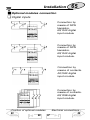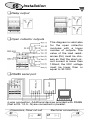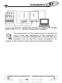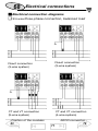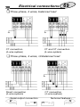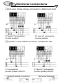
1
CARLO GAVAZZI
ING
CH
WM4-96: Modular Universal Utility
Meter and Power Analyzer
Harmonic analysis; Energy meters;
Load profile; Plug and play module
system; SMS reception and transmission. These are only a few among
many other functions performed by
your WM4-96. What’s more, Carlo
Gavazzi means ISO9001 certification,
a working experience of many
decades and a widespread presence
all over the world. All this because
we want our customers to have the
top service and the top products.
Welcome in the Carlo Gavazzi world
and compliments for your smart
choice. Visit our website and
evaluate our range of products:
CARLO GAVAZZI
C o m p o n e n t s
OOS
A u t o m a t i o n
A
K
To
p
TH
N
pe
r
YO
U
fo
rm
FO
an
R
ce
s
by
www.carlogavazzi.com
2
Index
WM4-96 Instruction manual: INDEX
CARLO GAVAZZI
WM4-96, 32-bit µ-processor based modular universal utility meter and power analyzer
FW rev.C.01
TO BEGIN WITH . . . . . . . . . . . . . . . . . . . . . . . . . . . . . . .5
■ Front panel description . . . . . . . . . . . . . . . . . . . . .7
■ Display adjustment . . . . . . . . . . . . . . . . . . . . . . . .7
DISPLAYING OF THE VARIABLES . . . . . . . . . . . . . . . . .8
■ Page “00”, starting page . . . . . . . . . . . . . . . . . . . .8
■ How to scroll the display pages . . . . . . . . . . . . . . .9
■ How the F key changes function depending on . . . .
the display page . . . . . . . . . . . . . . . . . . . . . . . . . . .9
❏ Pages from “00” to “13”: displaying of the . . . .
variables . . . . . . . . . . . . . . . . . . . . . . . . . . . . .9
❏ Pages from “14” to “18”: displaying of the . . . .
MIN and MAX values . . . . . . . . . . . . . . . . . . .9
❏ Pages from “19” to “24”: displaying of the . . . .
harmonic analysis . . . . . . . . . . . . . . . . . . . . .10
❏ Displaying of the Energy Meters . . . . . . . . . .11
❏ Page “25”: displaying of the total energy . . . . .
meters . . . . . . . . . . . . . . . . . . . . . . . . . . . . .11
❏ Page “26”: displaying of partial energies . . . .10
❏ Page “27”: displaying of GAS and . . . . . . . . . . .
WATER meters . . . . . . . . . . . . . . . . . . . . . . .12
❏ Page “28” displaying of the instrument’s . . . . . .
configuration . . . . . . . . . . . . . . . . . . . . . . . . .12
❏ Displaying of the load profiles . . . . . . . . . . . .12
❏ Displaying with “pass code” access . . . . . . . .14
❏ Pass “1000”: displaying of recorded events . .14
❏ Pass “999”: storage of the consumed energy .15
❏ Pass “998”: displaying of recorded var dmd 16
4
▲
▲
Index
4
Index
3
❏ Pass “997”: reset of data memory . . . . . . . . .16
❏ Pass “996”: reset of load profiles . . . . . . . . . .16
LET’S START . . . . . . . . . . . . . . . . . . . . . . . . . . . . . . . .17
■ Main menu . . . . . . . . . . . . . . . . . . . . . . . . . . . . . .17
■ Change password . . . . . . . . . . . . . . . . . . . . . . . .18
■ Inputs . . . . . . . . . . . . . . . . . . . . . . . . . . . . . . . . .18
❏ Analogue measuring input module . . . . . . . . . .
installed . . . . . . . . . . . . . . . . . . . . . . . . . . . . .18
❏ Analogue measuring input module . . . . . . . . . . .
not installed . . . . . . . . . . . . . . . . . . . . . . . . .21
❏ Enabling the tariffs’ remote control . . . . . . . .22
■ System . . . . . . . . . . . . . . . . . . . . . . . . . . . . . . . .25
■ CT ratio . . . . . . . . . . . . . . . . . . . . . . . . . . . . . . . .26
■ VT ratio . . . . . . . . . . . . . . . . . . . . . . . . . . . . . . . .26
■ Display page . . . . . . . . . . . . . . . . . . . . . . . . . . . .27
■ MIN MAX values . . . . . . . . . . . . . . . . . . . . . . . . .28
■ Selecting the events . . . . . . . . . . . . . . . . . . . . . . .29
■ Data storage . . . . . . . . . . . . . . . . . . . . . . . . . . . .30
■ Average values calculation . . . . . . . . . . . . . . . . . .31
ENERGY METERS MANAGEMENT . . . . . . . . . . . . . .34
■ Access to the management menu of the energy meters 34
❏ Single tariff management . . . . . . . . . . . . . . . .34
❏ Dual tariff management: whole year . . . . . . . .34
❏ Programming of the holidays period . . . . . . . .37
❏ Multi-tariff management of the energy meters 39
❏ Installed power . . . . . . . . . . . . . . . . . . . . . . .41
❏ Reset of the energy meters . . . . . . . . . . . . . .42
❏ Reset of the GAS meters . . . . . . . . . . . . . . . .43
❏ Reset of the WATER meters . . . . . . . . . . . . .43
OUTPUTS / OTHER SETTINGS . . . . . . . . . . . . . . . . . .44
■ Displaying of the harmonics . . . . . . . . . . . . . . . . .44
■ Setting of date/hour . . . . . . . . . . . . . . . . . . . . . . .44
■ Digital outputs . . . . . . . . . . . . . . . . . . . . . . . . . . .45
❏ Pulse output . . . . . . . . . . . . . . . . . . . . . . . . .46
2
4
▲
▲
Front panel
7
4
Index
❏ Alarms . . . . . . . . . . . . . . . . . . . . . . . . . . . . . .47
❏ Diagnostics . . . . . . . . . . . . . . . . . . . . . . . . . .48
❏ Remote control . . . . . . . . . . . . . . . . . . . . . . .49
■ Serial port . . . . . . . . . . . . . . . . . . . . . . . . . . . . . .49
❏ RS232 . . . . . . . . . . . . . . . . . . . . . . . . . . . . . .49
❏ Modem . . . . . . . . . . . . . . . . . . . . . . . . . . . . .50
❏ GSM . . . . . . . . . . . . . . . . . . . . . . . . . . . . . . .51
❏ How to use the SMS . . . . . . . . . . . . . . . . . . .52
❏ RS485 . . . . . . . . . . . . . . . . . . . . . . . . . . . . . .54
■ Digital filter . . . . . . . . . . . . . . . . . . . . . . . . . . . . . .54
■ Language . . . . . . . . . . . . . . . . . . . . . . . . . . . . . . .55
USEFUL INFORMATION . . . . . . . . . . . . . . . . . . . . . . . .56
■ What is ASY . . . . . . . . . . . . . . . . . . . . . . . . . . . . .57
INSTALLATION . . . . . . . . . . . . . . . . . . . . . . . . . . . . . . .59
■ Operations preliminary to the installation . . . . . . .59
■ Getting started . . . . . . . . . . . . . . . . . . . . . . . . . . .59
■ Front panel cut-out . . . . . . . . . . . . . . . . . . . . . . .61
■ Mounting the instrument . . . . . . . . . . . . . . . . . . .61
■ Position of slots and relevant modules . . . . . . . . .62
■ Available modules . . . . . . . . . . . . . . . . . . . . . . . .62
❏ Digital outputs module . . . . . . . . . . . . . . . . . .62
❏ Digital inputs / serial output modules . . . . . .64
❏ Power supply modules . . . . . . . . . . . . . . . . . .64
■ Optional modules connection . . . . . . . . . . . . . . .65
❏ Digital inputs . . . . . . . . . . . . . . . . . . . . . . . . .65
❏ Relay output . . . . . . . . . . . . . . . . . . . . . . . . .66
❏ Open collector output . . . . . . . . . . . . . . . . . .66
❏ RS485 Serial port . . . . . . . . . . . . . . . . . . . . . .66
ELECTRICAL DIAGRAMS . . . . . . . . . . . . . . . . . . . . . .68
❏ 3-phase connection, balanced load . . . . . . . .68
❏ 3-phase, 4-wire connection, unbalanced load 69
❏ 3-phase, 3-wire ARON connections . . . . . . . .70
❏ Single phase connection . . . . . . . . . . . . . . . .71
TECHNICAL FEATURES . . . . . . . . . . . . . . . . . . . . . . . .72
2
▲
▲
The connecting instrument
6
To begin with
5
HOW TO USE THE SYMBOLS
Go to the page where the previous main subject
is described.
▲
Go to the page where the next main subject is
described.
▲
Go to the page where the subject written on the
top of the current page starts.
Go to the page where the subject written on the
top of the current page ends.
This symbol indicates a particularly important subject or information.
This symbol indicates that more details are given
on the current subject.
We suggest you to keep the original packing in case
it is necessary to return the instrument to our
Technical Service Department. In order to achieve
the best results with your instrument, we recommend you to read this instruction manual carefully.
■
WM4-96 PHILOSOPHY (IMPORTANT)
WM4-96 is able to meet all the requirements in the
field of energy management and of power quality analysis.
WM4-96 can work, according to the needs, in three different operating modes, obtained by means of hardware and
software configurations.
- direct measurements for monitoring the network quality
and energy metering (LV or MT/HV connection).
Index
▲
How to scroll the pages
7
▲
3
9
6
To begin with
-
indirect power energy measurements by interfacing the meter
of the energy supplier (LV or MV/HV connection);
- direct measurements for the instantaneous variables (LV
connection) and indirect measurements for the energy
variables (LV or MV/HV).
In all operating modes it’s possible to add the management of water
and gas meters and the tariff management of the energies both from the
instrument and from external inferfacings. The easy management and
flexibility of WM4-96 is possible thanks to the plug and play modular
technology by Carlo Gavazzi and to a powerful 32-bit µProcessor. Also
the analogue measuring input module can be adapted to the users’
needs: the instrument acknowledges its presence adapting its electric
features and its operating mode accordingly. The following icons will help
the user to identify the instrument’s modifications.
The menu, without
measuring input module, is no more available
The menu, being without
measuring input module,
is modified.
The manual describes the modification of the menu
in case the measuring inputs module is not installed.
■
WM4-96: the connecting instrument.
WM4-96 “enjoys communicating”:
• through the wide graphic display and the easily readable
graphs such as the LOAD PROFILES or the harmonic distortion hystograms;
• through sending and receiving SMS messages by means
of the GSM mobile network. For example, by sending an
SMS message to a pre-defined mobile phone number,
WM496 informs the user that an alarm has been enabled
or disabled; the user himself can ask the instrument, by
an SMS, information about the measured variables.
5
7
▲
▲
Page 00
8
To begin with
7
■ Front panel description
Exit from the menu
and cancel the
choice you have
made.
It allows the user to
access some functions relating to the
displayed variables.
Access to programming or
settings’ confirmation.
Scroll to
the next
page
Scroll to the
previous page
Alphanumeric indication by means of a 7-segment
graphic LCD (128x64 dpi):
• of the measured variables;
• total number of energy meters: 4 (9 digits);
partial: 48 (6 digits);
• time periods: 4 programmable within 24 hours;
• programmable seasons: 3 within 12 months.
■ Display contrast adjustment
In order to get the best readability of the display, hold the
keys ▲ and ▼ pressed simultaneously, until the desired
readability is reached; the adjustment is cyclical.
The contrast can be adjusted only during the
measuring phase (from page 00 to page 28).
Energy meters
5
▲
▲
WM4-96 philosophy
5
11
8
Displaying of the variables
■ Page “00”, Starting page
When the instrument is swtched on, the main page of variable
displaying is shown. The first page, called page “00”, is the only one
configurable by the user who can choose the variables to be displayed in the 4 displaying areas. In all the other pages the type of
variables displayed in the four displaying areas is automatically
selected and cannot be changed. In the table on page 59 you can
see the contents of all the pages that can be displayed by WM4-96.
Measured variables
Clock
Number of
the displayed
page
The bottom part of the display, where the status of the digital
output is indicated in 4 specific sections, is common to all the
pages. If the outputs are not present, only an empty black rectangular frame is shown, if the outputs are present, the display will
show a letter followed by a number. Four different letters may
appear:
“P” indicates a pulse output
"A" indicates an alarm output. In this case the letter can be white in
a black background to indicate that the output is in alarm, or
black in a white background to indicate that the output is not in
alarm.
"D" indicates a diagnostic output. This is a particular type of alarm
that is activated when the neutral wire connection is missing.
The alarm is active when the background is black, while the
alarm is not active when the background is white.
“R” Remote control is activated (see Remote Control on page 49)
The NUMBER that follows the letter is the progressive number of
the output (from 1 to 4).
Index
▲
Harmonic analysis
16
▲
3
10
Displaying of the variables
■
9
How to scroll the various pages
To scroll the various pages, use the ▲ and ▼ keys.
Pressing the S key in any one of the display pages,
you access to the programming phase. The F key,
on the contrary, has various functions depending on the
selected page.
■
How the F key changes function depending
on the display page.
❑ Pages from "00" to "13" (00 only without measuring input module). Displaying of the variables
F key enabled if the alarm latch function is activated,
access to the reset of the latch alarms. To reset the latch
alarm press the F key; after that the instrument will display: “ WILL YOU RESET THE LATCH ALARMS?”; If you
choose S you will enable the reset procedure, if you
choose F there won’t be any reset. The reset of the latch
alarm is only available if the alarm event is finished.
❑
Pages from "14" to "18" (from 01 to 02 without
measuring input module). Displaying of the “MIN”
and “MAX” values.
The F key is active, that means you have access to
the reset function of the “MIN” and “MAX” values. To reset
the “MIN/MAX” recording, proceed as follows: enter the
function by pressing the F key, after that a message will
appear: “WILL YOU RESET MIN/MAX VALUES? WILL YOU
CONTINUE?"; if you choose F there won’t be any reset,
if you choose S the reset will not be made. The ▲ and
▼ keys allow you to select the range/value that you want
to reset; to confirm the reset press the S key again. To exit
the function press the F key again.
Front panel
▲
Load profiles
8
16
▲
7
13
10
Displaying of the variables
❑ Pages from "19" to "24" (from 10 to 11 in single
phase mode) Displaying of the harmonic analysis
When the instrument is supplied, these pages are
not enabled, see page 44 to enable them. The F
key is active: access to the detailed analysis of the
harmonics. After pressing the F key, a pointer appears
along the horizontal axis (see figures below). To display the
data relating to the single harmonics move along the histogram using the ▲ (moves from left to right) and ▼
(moves from right to left) keys. For each harmonic the instrument measures the % value with reference to the fundamental and the single harmonic angle between the “V” harmonic and the “A” harmonic of the same order.
SIMPLE ANALYSIS:
Line phase being measured
and relevant voltage or current value (L1-L2-L3).
Total harmonic distortion and
relevant value in percentage
F
F
DETAILED ANALYSIS:
Harmonic order (h1 to h50),
of the phase being measured
(L1-L2-L3) and relevant
absolute current or voltage
value of the harmonic.
Harmonic order (h1 to h50),
relevant conventional sign
(- or +) and value of the harmonic given in percentage.
The pointer
shows which
harmonic is
being measured
Phase angle between the voltage and current harmonic
of the same order: a phase angle between 0° and 90° and
between 270° and 360° corresponds to a generated harmonic; an angle between 90° and 180° and between 180°
and 270° corresponds to an imported harmonic.
Display of Gas Water meters
8
16
▲
▲
WM4-96 philosophy
5
12
11
Displaying of the variables
0°
Generated
270°
90°
Imported
180°
Harmonics:
This angle is displayed only if the measurements
are taken in a three-phase system with neutral
❑
❑
Pages relating to the energy meters
Page "25" (3 without measuring input module)
Displaying of the total energy meters
F
key disabled.
❑ Page "26" (4 without measuring input module)
Displaying of partial energies
F key is active; modification of tariff/displayed period.
By pressing the F key for the first time, the range relating
to the season is highlighted. By using the ▼ and ▲ keys,
it’s possible to change the season displayed in that page.
Pressing the F key once again, the range relating to the
period is highlighted. Using the ▼ and ▲ keys, it’s possible to change the tariff period within the displayed season.
Pressing the F key for the third time, you go back to the
measuring page.
The changes of season and tariff period only refer to the displaying of the values stored in the corresponding season
and period.
The changes carried out in this page do not have any
influence on the method of tariff management of the
instrument; they are only valid for display purposes.
8
Pass 999
16
▲
▲
Displaying of min/max values
9
15
12
Displaying of the variables
❑ Page "27" (5 without measuring input module)
Display of Gas and Water meters
F keys disabled. Depending on the setting, the instrument may display one only of the following meter combinations: Gas; Gas with Gas in night tariff; Gas and Water. The
water and gas meters are managed by the digital inputs.
❑ Page “28” (6 without measuring input module)
Displaying of instrument configuration
F key disabled. Page 28 shows the configuration of
the main input (IN) and output (OUT).
Alarms
(A1-A2-A3-A4).
Diagnostic
(D1-D2-D3-D4).
Puse outputs
(P1-P2-P3-P4).
Digital inputs.
The letters and numbers between parenthesis are referred to
the relevant slots, while the text on their right shows the variable referred to the output. With reference to the digital inputs
(DIG.INP.), the ON/OFF status of each one of them is shown.
❑ Displaying of load profiles
The load profiles are a simple graphic representation useful to highlight the trend of the load consumption (integrated
power) with reference to the installed power (as per contract).
This function needs the serial module AR1041 to be installed.
The instrument calculates and displays the load profiles
Front panel
▲
Pass 1000
8
16
▲
7
14
Displaying of the variables
13
Load profile of the
installed power divided
into hour time periods
Wdmd of the last integration
period
Time of the last integration
Installed power
Example: the consumed power integrated
in 15 minutes exceeds
the installed power
Graphic representation
of the consumptions
F
Pressing F , the instrument
will display in detail the data indicated by the arrow that will
appear on the abscissae axis.
To scroll the single data use the
F
F
keys. To exit the detailed
display mode press F .
Daily graph:
15-minute resolution,
total time: 24 hours.
Weekly graph:
2-hour resolution,
total time: 7 days.
Monthly graph:
12-hour resolution,
max. total time: 31 days.
depending on the acquired data, dividing them into: daily,
weekly and monthly graph, as simplified by the figures shown
above. Press the F key: you can display the single integration periods and the details relevant to the installed power
8
Access to the main menu
16
▲
▲
Displ. of partial energies
11
17
14
Displaying of the variables
programmed for that hour time period, the storage time of the
Wdmd sample and the relevant value. The data can be
scrolled by means of the ▲ and ▼ keys and are relevant to
the indication of the arrow that appears on the ascissae axis.
To go back to the normal display, press the
F
key again.
If the instrument has not acquired enough data to
cover the resolution of the graphs (day: at least 15
minutes; week: at least 2 hours; month: at least 12
hours) the latter are not displayed and the message: “NOT
AVAILABLE” appears. When the data are enough for the grahph to be displayed, wait a few seconds for the acquired data
to be processed.
❑ Displaying with access to the Pass Code
❑ Pass "1000": Displaying of recorded events
(Only if the RS232 + RTC module + data memory is present)
Press the S key in any of the measuring page (excluded the “load profiles”) when the instrument asks for
, set the value “1000” and confirm with
S ; the instrument shows you the page where the events
are displayed and where the instrument stores, in a chronological order, the alarms that have occurred until that
moment. To go back to the variable page press the F key.
The last event has always the number 1 while the number
corresponding to the first event varies, depending on the
number of events that have been previously stored. The figure on the following page explains you the meaning of the
displayed information.
8
Pass 997
16
▲
▲
Measuring pages: 00 to 13
9
16
Displaying of the variables
15
Only for alarms and diagnostics: detection of the
abnormal condition (ON) or
return to the normal condition (OFF)
Control type:
alarm (e.g.: A2),
diagnostics (e.g.: D1),
maximum value (MAX),
minimum value (MIN).
Variable being
controlled.
Alarms: value of
the ON alarm;
Max and Min logging: maximum
and minimum
measured values.
Time of the
event.
Date of the
event.
To reset all the events press the S key, to continue the
reset procedure press the S key again: to exit from the
reset procedure press the F key.
❑ Pass "999": display of energy consumption storage
(Only if the RS232+RTC is present)
The RS232+RTC module allows the user to display the storage
of the energy consumption of the previous two months. To enter
this function, press the S key in any one of the measuring page
(excluded the “load profiles”),
when the instrument asks for the
pass code
,
set the value “999”: the instrument shows you the page where
the energy values are stored.
Use the ▲ and ▼ keys to display the partial values;
press the
F
key to exit.
Load profile
▲
Input programming
8
16
▲
13
19
16
Displaying of the variables
❑ Pass "998": display of the stored dmd variables
(Only if the RS232 + RTC module is present)
The stored dmd variables can be displayed by pressing
the S key in any one of the measuring page (excluded the
“load profile” pages): when the instrument asks for the
, enter the value “998”: the instrument will
display the values of the stored variables, the time (hoursminutes-seconds) and the date (day-month) of storage.
Use the ▲ and ▼ keys to scroll
all the values; to exit press the F
key. If the value has not been
stored, the instrument displays
“NOT AVAILABLE VALUE”.
❑ Pass "997": Reset of the Data Memory (only if the
RS232+RTC module is available)
It’s possible to reset all the information stored in the data memory. To enter this function press the S key in any one of the
measuring pages (excluded the “load profile” pages), when the
instrument asks for
, enter the value “997” and
confirm with S , then press S to confirm the reset; press F
not to execute the reset.
❑
Pass "996": Reset of the load profiles
It’s possible to reset all the information relating to the
load profiles. To enter this function, press the S key in any
one of the measuring pages (excluded the “load profile
pages”), when the instrument asks for
enter the value “996” and confirm with S , then press S again
to confirm the reset, press F not to execute the reset.
Inputs
8
▲
▲
Energy Meters pages
11
18
Programming
17
It is very important to verify that, every time the
configuration of the instrument (modules and/or
associated variables, electrical systems, etc.)
changes, the setting of the parameters is
according to the new configuration.
■ Access to the main menu
S
F
Press the S key to access
to the programming menus from
the measuring and displaying
phase (you cannot access the
main menu if the instrument is in
the displaying pages of the load
profiles); when the instrument
asks for the password, enter its
correct value by means of the
▲ and ▲ keys; then confirm
S
▲
1.2..
..2.1
▼
F
it by pressing the S key again.
If the password is correct (the
default password is 0) you are
allowed to access to the main
menu of the programming
phase. To reset your choice and
go back to the measuring mode,
press F .
MENU title
Scroll bar
Menù
Instrument’s revision
Serial number
Pass 999
▲
Digital inputs progr.
33
▲
15
21
18
Programming
■ Change Password
This function allows you to
choose the desired password
value (from 0 to 500).
S
Press the S key and when the
new password value is required,
enter the desired value by means
F
of the ▲ and ▼ keys; then
S
▲
1.2..
..2.1
▼
press the S key to confirm the
new value.
The instrument goes back to the
main menu, as shown in the figure on the left. To reset your
choices and go back to the main
Measure
F
menu press F .
■ Inputs
Depending on the hardware
configuration being used, the
instrument works in two different
operating modes:
S
❑ With installed analogue measuring input module (AQ1018AQ1019).
F
S
F
The instrument carries out all
the measures of: instantaneous,
power, THD variables and energy metering. It’s also possible to
select the gas and water metering, as well as gas and night tarLoad profiles
▲
A3-C3 Inputs
17
33
▲
13
20
Programming
19
iff gas metering: to do this the
AQ1042 digital inputs + aux module must be installed in slot A.
Choose the “INPUTS” function by
S
F
means of the ▲ and ▼ keys
S
▲
and press S to enter in the submenu. Choose the “MEASURE”
▼
F
function by means of the ▲ and
S
▲
S
▲
▼ keys; press S to select the
relevant operating mode and enter
the relevant sub-menu where you
can select the digital inputs (if present in slot A) connected to the gas,
water and energy meters.
1- Choose the A1 INPUT (gas or
▼
1.2..
..2.1
▼
kWh- meter) by means of the ▲
and ▼ keys (the description of
the selected input function and the
weight of the connected pulse can
be seen under the scroll window);
S
▲ ▼
press S to confirm.
2- Once the ON/OFF window is
displayed, choose “OFF” by
F
S
▲
1.2..
..2.1
means of the ▲ and ▼ keys to
disable the metering and confirm
▼
with S ; choose “ON” to enable the metering: the following
window appears: selection between H2O/GAS and kWh- (generated Kwh) “ENERGY METER”; choose the desired type of
counter by means of ▲ and ▼ , confirm with S (if you
choose the kWh- metering, also the A2 input for counting the
17
List of digital inputs
33
▲
▲
Access to the main menu
17
23
20
Programming
kvarh- will be enabled).
3- Once the desired type of meter is confirmed, the instrument asks for the number of pulses to be associated to the
unit increase (e.g. if you type the value 10 you will need 10
input pulses in order to make the instrument display 1 m3).
4- A2 INPUT, enabling function of the water metering or of
the kvarh- meter (generated kvarh); ENERGY METER” follow the operations described on paragraphs 1 and 2. If the
H2O/GAS meter is selected, the window for the selection of
the night gas tariff appears: GAS TARIFF or WATER METER
for the water meter. Choose the desired option by means
of the ▲ and ▼ keys and confirm with S . By choosing “WATER METER” or kvarh- meter (when the kvarh is
chosen, automatically also the A1 input is enabled to count
kWh-) the instrument shows the box where the increase
pulses to be associated with the unit increase are to be
entered (e.g. if you enter the value 10 you will need 10 input
pulses for the instrument to display 1m3). Press F to go
back to the previous menus.
- A3 and C3 INPUTS: see “Enabling the remote control of
the tariffs” on page 22.
- C1 and C2 INPUTS: not available.
Inputs A1 and A2 must both count either energies
or m3 (GAS/H2O); if for example you choose A1
as Wh- meter and then you select A2 as H2O
meter, WM4 automatically changes the A1 input
as GAS meter.
17
Tariffs remote control
33
▲
▲
Display of consumed energy
15
22
21
Programming
❑ Analogue measuring
input
module
NOT
installed
(AQ1018 - AQ1019).
The instrument carries out
only the following measures: W,
var, Wdmd, vardmd, PFdmd using only
the pulses acquired through the
digital inputs. The “VA” power is
always 0. It’s possible to count
and display the measurements of:
water and gas, gas and gas night
tariff, or Wh- and varh meter. In
order to make the instrument carry
out the above mentioned measures, it’s necessary that both digital input modules are mounted
(AQ1042+AQ1038 or 2x AQ1042).
Choose the INPUT function by
S
F
S
F
S
F
pressing the ▲ and ▼ keys,
then press S to enter the relevant sub-menu. Choose the
PULSE function by means of the
S
F
▲ and ▼ keys and press the
S key to select the operating
mode and enter the relevant submenu where you can select the
digital inputs associated with the
gas / water and kWh/kvarh meters. You can also enable the
two digital inputs relevant to the remote selection of the tariffs. To select the water / gas metering or Wh- varh- metering, follow steps 1 to 4 on page 19 and 20. Please note the
description of the selected input function and the weight of
the associated pulse under the relevant window. To enable
▲
1.2..
..2.1
▼
Digital input prog.
System
17
33
▲
19
▲
S
25
22
Programming
the counting of the “W” and “var” energies proceed as follows:
5- Choose the C1 INPUT function by the ▲ and ▼ keys
(see the description of the selected input function and the
weight of the associated pulse under the scrolling window);
press S to confirm.
6- Once the ON/OFF window appears, choose “OFF” by the
▲ and ▼ keys to disable the counting of kWh’s and confirm with S ; choose “ON” to enable the counting of kWh’s
and confirm with S .
7- The instrument asks the user to enter the number of pulses to be associated to the unit increase (pulse/ kWh, ex.:
entering the value 10 the instrument will need 10 input pulses to display 1kWh on the counter).
8- For the C2 INPUT, enabling function of the “kvarh” counting, follow steps 5 to 7. To go back to the previous menus,
press F .
❑ Enabling the tariffs
remote control
S
This function enables the
control of the tariff phases of the
energy counters by means of
external pulses and not by
means of the instrument’s clock.
From the PULSE sub-menu
select and enable the “A3
INPUT” and “C3 INPUT”. Select
them one at a time by means of
F
S
F
S
▲
1.2..
..2.1
▼
17
Tariff table
33
▲
▲
Entering the main menu
17
24
Programming
the ▲
23
▼ keys, confirm with S . When the ON/OFF win-
dow appears select ON by means of the ▲ ▼ keys to
enable the INPUT or OFF to disable it, then confirm your
choice by means of the S key. Press F to go back to
the previous menus.
WM4-96 is able to recognize the presence of the
analogue measuring input module (AQ1018AQ1019). If you try to enter the MEASURING menu
when the measuring input module is not installed,
the instrument displays NOT AVAILABLE. There’s a lower
quantity of display pages in the configuration without measuring inputs, since there’s a lower number of data that can be
measured. On the contrary the digital inputs are not recognized automatically by the instrument and it is therefore important to program them correctly: ON if they are
to be used and OFF if they are not to be used, so as to
avoid any wrong measures. If WM4-96 is used in the
PULSE operating mode, it needs a full scale to be set: therefore if the measuring module is not installed, the value to be
set is in the SYSTEM menu (see SYSTEM on page 24). To
sum up, here is the list of parameters to be set depending on
the requirements (# Not available when analogue measuring
input module is installed (AQ1018 or AQ1019):
A1 INPUT
A2 INPUT
A3 INPUT
C1 INPUT#
C2 INPUT#
C3 INPUT
(channel 1 slot A): enables gas counter.
(channel 2 slot A): enables water counter or
gas night tariff.
(channel 3 slot A): enables management of
energy meters time periods
(channel 1 slot C): enables kWh meter.
(channel 2 slot C): enables kvarh meter.
(channel 3 slot C): enables management of
energy meters time periods.
Display page
17
33
▲
▲
Digital input prog.
21
27
24
Programming
TIME PERIODS SELECTION MODE
CHANNEL 3 SLOT A CHANNEL 3 SLOT C ACTION
Open
Open
Tariff 4
Open
Close
2 Winter / 3 Summer *
Close
Open
1 Winter / 2 Summer**
Close
Close
Tariff 4
CHANNEL 2 SLOT A (if A2 enabled as GAS): Close = day-time
tariff GAS is selected. Open = night-tariff GAS is selected.
*
WM4-96 associates to the meter tariff 2 in Winter and
tariff 3 in Summer.
** WM4-96 associates to the meter tariff 1 in Winter and
tariff 2 in Summer.
When the tariff mode managed by the digital inputs (A3 and
C3 enabled “ON”) is selected, the user can no longer select
the tariffs in the energy meters menus, but only the seasons.
Example 1: measure of all the instantaneous variables,
energies and gas + night gas. Proceed as follows: install the
analogue measuring module (AQ1018 or AQ1019), select
MEASURE in the INPUTS menu and enable the AQ1042 digital inputs module (that must be installed) by setting A1 ON,
A2 ON (GAS TARIFF), A3 OFF.
Example 2: measure of energies, powers dmd and PF’s
dmd, as well as remote management of the tariff periods from
the digital inputs. The instrument is to be equipped with 2 digital input modules (AQ1042 slot A and AQ1038 slot C or 2x
AQ1042 slot A and C), while the analogue measuring module is
not necessary; to enable the 2 modules, set the instrument as
follows: A1 OFF, A2 OFF, A3 ON, C1 ON, C2 ON, C3 ON. Then,
set the full scale in the SYSTEM menu according to your plant.
Every modification to the measuring mode will
reset the meters.
17
VT-CT ratio
33
▲
▲
Digital inputs programming
19
26
Programming
25
■ System
S
▲
▼
F
S
▲
This function allows the
user to select the type of
electrical
system
by
choosing among single phase (1phase), balanced three-phase plus
neutral (3+N phases bal.), unbalanced three-phase plus neutral (3+N
phases unbal.), three phase balanced (3 phases bal) and threephase unbalanced (3 phases unbal).
Choose the SYSTEM function by
means of the
▼
▲ and ▼ keys,
press S to confirm, then select the
desired system by means of the ▲
and ▼ keys and confirm with S .
To reset your choice and go back to
S
▲
▼
F
the main menu, press the F key.
If the measuring input
module is not present, the
menu is to be modified by
displaying the selectable full scale
powers. Select the required full scale
power by means of the
▲ and
▼ keys and confirm with
S . To
reset your choice and go back to the
▲
main menu, press the F key.
▼
Any modification to the system settings will make
the MIN/MAX values, the events and the energy
meters reset.
List of digital inputs
Events selection
17
33
▲
23
▲
S
29
26
Programming
■ CT ratio
S
▲
This function allows you to
select the value of the CT
ratio. Example: if the primary of the CT (current transformer) being connected is 300A
and the secondary is 5A, the CT
ratio corresponds to 60 (obtained
from the calculation: 300/5).
Choose the function CT RATIO by
▼
F
means of the ▲ and ▼ keys;
S
▲
1.2..
..2.1
▼
press S to confirm then select
the desired value by means of the
▲
and ▼ keys and confirm
with S . To reset your choice and
go back to the main menu, press
F .
If the CT ratio is modified, then all the MIN/MAX values and the partial energy meters are reset.
■ VT-PT ratio
▲
S
This function allows the
user to select the multiplier
value of the VT. Example: if
the primary of the VT (voltage
transformer) being connected is
20kV and the secondary is 100V,
the VT ratio will be 200 (given by
20000/100). If there is no VT, the
ratio will be “1.0”.
▼
F
Min/Max values
17
33
▲
▲
Digital inputs prog.
21
28
Programming
27
Choose the function VT-PT RATIO
by means of ▲ and ▼ ; to confirm press
S ; then select the
desired value by the ▲ and ▼
S
▲
1.2..
..2.1
▼
keys and confirm with S . To
reset your choice and go back to
the main menu, press F .
Changing the VT ratio, all the MIN/MAX values, all
events and partial energy meters are reset.
■ Display page
S
▲
This function allows you to
select the variables to be
displayed on page 00.
Choose the DISPLAY PAGE func-
▼
F
tion by means of the ▲ and ▼
keys; press S to confirm, then
select the desired section of the
display using the ▲ and ▼
▲
keys; Press S ; then select the
variable to be displayed by means
▼
of the ▲ and ▼ keys and confirm it with S . To reset your
choices and go back to the main
menu press F .
System
Average calculation
17
33
▲
25
▲
S
31
28
Programming
■ MIN MAX VALUES
▲
S
This function allows the user
to associate some variables
to the automatic recording
of maximum values (from MAX1 to
MAX12) and minimum values (from
MIN1 to MIN8). To use this function,
proceed as follows: select the MIN
MAX VALUES function from the
▼
F
main menu using the ▲ and ▼
keys and confirm it with S .
A new window will appear showing
you the list of the available memory
locations: scroll the locations using
the ▲ and ▼ keys, starting
from MAX1 for the maximum values and MIN1 for the minimm val-
▲
S
ues. Press S to open the secondary menu with the list of the
available variables to be selected.
Scroll the list of the variables using
▼
F
the ▲ and ▼ keys; once you
have selected the desired variable,
confirm it using S . To reset your
choices and go back to the main
▲
S
▼
menu, press F .
Once you have confirmed the selection, the following
message will appear: “YOUR CHOICE WILL RESET
THE VARIABLE, WILL YOU CONTINUE? YES/NO”.
Note: to enable the MIN/MAX recording function, read
carefully the following paragraph, SELECTING THE
EVENTS.
Data Logging
17
33
▲
▲
List of digital inputs
23
30
Programming
29
■ EVENTS SELEC.
S
▲
This function allows the
user to enable the events
for data logging:
• MAX (logging of up to 12 different variables MAX1 to MAX12), see
also: MIN MAX VALUES;
▼
F
• MIN (logging of up to 8 different variables MIN1 to MIN8), see also MIN MAX
VALUES;
• D "diagnostics" (logging of up to 4 alarms:
from D1 to D4), see also: DIAGNOSTIC DIGITAL OUTPUTS
• R "remote control" (up to 4 remotely controllable outputs: from R1 to R4), see also:
REMOTE CONTROL DIGITAL OUTPUTS;
• A "alarms" (logging of up to 4 alarms:
from A1 to A4), see also: ALARM DIGITAL
OUTPUTS;
To use this function, select “EVENTS
SELEC.” from the main menu using the
▲ and ▼ keys and confirm it pressing
S . Use the ▲ and ▼ keys to select
where you want to enable the event (ON) or
disable it (OFF). The function of the S ONOFF-ON key is cyclical. To go back to the
main menu press F .
S
▲
▼
When the measuring input module (AQ1018AQ1019) is not present, the user can select only up
to 8 events (even though the menu remains
unchanged): from MAX 1 to MAX 4 and from MIN 1
to MIN 4. To select them, proceed as described above.
Display page
▲
Avg calculation, graphs
17
33
▲
27
33
30
Programming
■ Data logging
▲
S
This function enables the logging
of the required variables in the data
logging.
1) Choose the function DATA LOG-
▼
F
▲
S
GING by means of the ▲ and ▼
keys, press S to confirm;
2) select “DMD VARIABLES” by
▼
F
▲
S
means of the ▲ and ▼ keys and
confirm with S ;
3) the display shows the window with
the list of the available DMD variables:
select the required available (ON) vari-
▼
F
able by means of the ▲ and ▼
keys and confirm with
▲
S
▼
F
▲
S
S . To go
back to the main menu press F .
To select the integration time
reapeat step 1; then select TIME
INTERVAL by means of the ▲
▼
and ▼ keys and confirm with S : the display shows the window for the selection of the TIME INTERVAL.; select the value (in
minutes) with the ▲ and ▼ keys and then confirm with S .
To go back to the main menu press F .
During the measurement the instrument takes a sample of the selected variables every 200ms approx.;
When the selected time (from 1 to 60 min.) expires,
the instrument will calculate the average of the samples and carry out the data logging. The historical
data will therefore be guaranteed to be highly accurate.
System
▲
Synchronization
17
33
▲
25
32
Programming
31
■ DMD/AVG calcul.
S
▲
This function allows you to
select the calculation
method of W-VA-PF. To
enter these functions, select
“DMD/AVG CALCUL” from the
▼
F
S
▲
main menu using the ▲ and ▼
keys and confirm the selection with
▼
S . You can thus enter the
DMD/AVG CALCUL. method:
choose between the FIXED or
F
S
▲
1.2..
..2.1
▼
FLOAT method using the ▲ and
F
S
▲
▼ keys and confirm your choice
with S . The display will show the
window for setting the time in min-
▼
F
S
▲
1.2..
..2.1
utes, use the ▲ and ▼ keys to
set the desired value, confirm with
S . To reset your choices and go
back to the main menu press F .
▼
The FLOAT selection is not available without the
measuring input module.
FIXED selection: if for example you select the value
15 minutes, the instrument calculates the average
and updates the value every 15 minutes.
FLOAT selection: if for example you select the value
“15 minutes”, the instrument calculates the average and
Events selec.
▲
Dual-time prog. meter
17
33
▲
29
35
32
Programming
updates its value at first after 15 minutes and afterwards
every minute generating a window whose width corresponds to “15 minutes” and shifts by units of 1 minute.
On the following page you can see the diagram that shows
the two operating methods.
SYNCHRONIZATION OF THE FIXED OR FLOAT CALCULATION
The synchronization of the FIXED or FLOAT calculation can
be carried out in three different ways:
• without DIGITAL INPUTS and RS232+RTC modules:
the reset and the start of the synchronization is carried out
when the instrument is switched on;
• with the DIGITAL INPUTS module installed:
the synchronization begins when the A3 and C3 digital
input modules change state (from ON to OFF or from OFF
to ON). Any following change of state will make the synchronization reset and start all over again;
• with the RS232+RTC module: the synchronization begins
at the exact hour that follows the “switch on” of the instrument (E.g.: if WM4-96 is switched on at 10:25, the synchronization will begin at 11:00).
In case both modules are installed (that is digital
inputs and RS232+RTC) the priority will be given to
the digital inputs.
Display page
▲
Energy meters
17
33
▲
27
32
Programming
33
FIXED AVERAGE CALCULATION
Where:
Pmax is the maximum measured power,
Pc is the contractual power,
t1 is the selected average period
FLOAT AVERAGE CALCULATION
17
Holidays period
▲
▲
DMD/AVG calculation
31
37
34
Counters Management
■
Access to the Counters
menu
▲
S
This function allows you to
choose the type of management
of the energy meters. Select
“COUNTERS” from the main
▼
F
menu by means of the ▲ and
▼ keys; confirm with S to
enter the specific sub-menu.
❑
SINGLE TARIFF Counters
Management
▲
S
This function allows you to
choose the energy meters according
to a single tariff which is the same for
the whole year. Select SINGLE TARIFF
▼
by means of the ▲ and ▼ keys
and confirm your choice with S .
When you change the type of management, and
after the choice is confirmed, the instrument resets
the meters and a buzzer sounds.
❑ DUAL TARIFF counters management: Whole year
This selection manages the energy meters with two different tariffs per day and two periods per year. Select DUAL
TARIFF from the COUNTERS menu by means of the ▲
and ▼ keys and confirm your choice with
S . Select
WHOLE YEAR and confirm with S to enter the relevant
menu; now you can enter the programming of the daily period as follows:
Tariffs examples
43
▲
▲
Events Selection
29
36
Counters Management
35
1-press S : the first box (trf=tariff) is highlighted;
S
▲
2-press S again: the TARIFF box
will appear on the lower part of the
display; now you can choose the
tariff (from 1 to 4), e.g.: “1” by means
▼
F
S
▲
of the ▲ and ▼ keys;
▼
F
3-press the S key once more,
the “end tariff” hour is highlighted;
4-press the S key once more; the
HOURS box will appear on the
lower part of the display; now you
can choose the hours - e.g. 8 - by
S
S
▲
1.2..
..2.1
means of the ▲ and ▼ keys.
▼
5-press the S key again; the “end
tariff” minutes will be highlighted;
S
S
▲
1.2..
..2.1
▼
6-press the S key again: the MINUTES box will appear on the lower
part of the display; now you can set
the desired minutes - e.g. 10 - by
S
S
▲
▼
S
▲ F ▼
1.2..
..2.1
means of the ▲ and ▼ keys.
7-after the confirmation of the last
setting, press S and you are back
to the selection of the first “trf”
parameter you have highlighted.
The “starting hour” of the following
line becomes equal to the “end
hour” you have just selected. Only
when the “trf” parameter is highlighted, you can scroll the parameters and modify them: use the
Proceed with the
same principle for
the following rows.
To exit any item
always use F .
S key to access to the parame-
Multitariff counters
34
43
▲
▲
Graphs, AVG calcul.
33
39
36
Counters Management
ters; use the ▲ key to move from the left to the right and the
▼ key to move from the right to the left.
8- press F to exit the programming of the parameters of
the relevant row (no boxes are to be highlighted);
9-press ▲ and ▼ to select one of the other programming
lines; the pointer on the right shows the line where the user
can modify the parameters (steps from 1 to 7);
a) the day can be divided into up to 8 different periods connected to up to 4 different tariffs according
to the following working principle:
20
22
24
2
trf1
4
18
+ kWh
- kWh
+ kvarh
- kvarh
6
16
8
14
12
10
1
Imported active energy
Exported active energy
Imported reactive energy
Exported reactive energy
The measured energy (partial energy) is placed in TARIFF 1
when the time period is from midnight to 8:00, in TARIFF 2 when
the time period is from 8:00 a.m. to 8:00 p.m. and again in TARIFF1 when the time period is from 08:00 p.m. to midnight. The
total measured energy is the result of the sum of all the partial
measures as shown in the figure below:
trf1
20
22
24
2
trf1
4
18
+ kWh
- kWh
+ kvarh
- kvarh
1
16
+ kWh
- kWh
+ kvarh
- kvarh
8
14
12
10
trf2
T
+ kWh
- kWh
+ kvarh
- kvarh
6
2
b) the starting point of the first time period is always 24:00
(midnight) and cannot be changed;
c) the starting point of the following period is always the end
Tariffs examples
43
▲
▲
Events selection
29
36
Counters Management
37
hour of the previous time period;
d) the daily loop is closed by setting 24:00 as last hour of the
last time period (to follow this procedure see step 4 on page
35), confirm the setting by pressing S and F to go back
to the TARIFF SELECTION menu (“COUNTERS” submenu
on page 34).
NOTE: selecting the A3 or C3 digital inputs as ON,
the DUAL TARIFF is no more available.
❑ Programming the
HOLIDAY period
S
▲
To program the HOLIDAY
period, proceed in the following
way:
10-Choose HOLIDAY in the
DUAL TARIFF menu by means of
▼
F
S
▲
▼
F
the
firm with S : the HOLIDAY window will be displayed;
1.2..
..2.1
▼
11-press ▼ : the month corresponding to the start date will be
highlighted;
1.2..
..2.1
▼
12-press S : the box where the
month can be set is enabled;
1.2..
..2.1
▼
13-use the ▲ and ▼ key to
select the desired month (from 1
to 12);
1.2..
..2.1
▼
On page.38
14-press the S key to confirm
the selection and move to the
next parameter: day setting;
Avg calculation, graphs
Multi-time Energy Counters
34
43
▲
33
S
▲
▼
S
▲
S
S
▲
S
S
▲
S
S
▲
S
▲ and ▼ keys and con-
39
38
Counters Management
15-press the S key again to open the box where the day
is to be set,
16-use the ▲ and ▼ keys to select the desired day (from
1 to 31 depending on the previously selected month);
17-press the S key to confirm the selection and move to
th next parameter.
To program the “end date” follow the same procedure
described above from step 11 to step 16. After confirming
the “end” day by means of the S key, the HOLIDAY Box is
highlighted to indicate the conclusion of the HOLIDAY period programming cycle. You can
From p. 38
To p. 38
also use the ▲ (moves from
S
F
S
S
▲
S
1.2..
..2.1
▼
right to left) and ▼ (moves from
left to right) keys to scroll along
the available parameters.
It’s possible to choose the tariff to
be associated to the HOLIDAY
period according to the following
procedure: starting from the box
on the previous page, step 10,
press the S key again: the
instrument will display the box
shown on the left. Press S : the
box relevant to the “trf” value is highlighted; press the S
key again: the instrument will display on the lower section
the box where the tariff is to be set. Select the desired tariff
(from 1 to 4) by means of the ▲ and ▼ keys and confirm
it with
S . To reset your choices and/or exit the menus,
use the F key.
Trf Holiday period
34
43
▲
▲
Average calculation
31
38
Counters Management
39
❑ MULTI TARIFF
This function allows the management of the counters
according to many periods per day and three periods per
year: WINTER, SUMMER and HOLIDAY.
S
▲
To program the parameters relating to the winter season, simply
follow the same procedure (holidays) described on page 37 from
Step 11 to Step 17. The parameters of the SUMMER season are
automatically set by the instrument as a difference between
the previous two periods of the
Year. To enable the setting of the
▼
F
S
▲
▼
F
daily time periods, press S
when the WINTER or SUMMER
seasons are highlighted. The following settings are the same as
the ones described from Step 1
to Step 9 on page 35 and 36. To
reset your choices and/or go
back to the previous menus, use
S
F
the
F
key. To program the
HOLIDAY period, follow the procedure on page 37 from
step 11 to step 17.
The WINTER and SUMMER periods are conventional seasons mainly used to manage in the best
way the different energy costs during the year.
The reminds at steps a), b), c), d) on page 36 and
37 are also valid for the MULTI TARIFF function. The next
page shows a few examples of programming the various
time periods.
Installed power
34
43
▲
▲
Dual tariff prog.
35
41
40
Counters Management
DUAL TARIFF management
trf1
20
22
24
2
trf1
4
18
6
16
8
14
12
10
WHOLE YEAR
trf start
end
1
OO:OO O8:OO
2
O8:OO 2O:OO
1
2O:OO OO:OO
1
TARIFF
trf2
As you can see on the figure above, there’s a daily division
into three periods with two different tariffs.
MULTI TARIFF management
trf1
trf4
20
22
24
2
trf1
4
6
18
trf3
16
trf2
WINTER
trf start
end
OO:OO O6:OO
1
2
O6:OO O8:OO
3
O8:OO 1O:OO
1
TARIFF
8
14
12
10
trf3
trf2
WINTER
trf start
end
1O:OO 16:OO
2
3
16:OO 18:OO
4
18:OO 21:OO
1
21:OO OO:OO
2
TARIFF
On the picture above you can see four different tariffs which
are coupled to seven different periods of the day.
34
Tariffs examples
43
▲
▲
Avg calculation, graphs
33
40
Counters Management
41
❑ Installed power
▲
S
This function allows the user
to set the maximum installed tariff power (as per contract). The
set power is associated to the
desired tariff (t1-t2-t3-t4) and it’s
displayed in the load profile
graph (see also load profiles on
page 12).
Select INSTALLED POWER from
▼
F
▲
S
the main menu by means of ▲
▼
and ▼ and confirm it with S
to enter the relevant submenu.
Then, select the required tariff
(t1-t2-t3-t4) by means of the
F
▲
▲
S
▼
and ▼ keys and confirm
with S . The full scale selection
window appears: select the
desired full scale value by means
F
of the ▲ and ▼ keys and
▲
S
confirm with S ; then, enter the
desired power value by means of
▼
the ▲ and ▼ keys and confirm with the S key.
To reset your choices and go back
to the main menu press F .
MINIMUM INSTALLED POWER: (MIN. INS. POWER) enables the
user to set the beginning of the scale of the load profiles graphs
thus optimizing its resolution. To set the value proceed as per
“installed power”.
Counters reset
34
43
▲
▲
HOLIDAY periods
37
43
42
Counters Management
❑ Reset of the Energy
Counters
▲
S
The “RESET” menu allows
you to reset the energy counters.
▼
F
Press S to enter the menu and
then use the ▲ and ▼ keys to
select the desired type of reset.
▲
S
Press S to enter the menu,
then the instrument displays the
following message:
▼
PAY ATTENTION, ALL THE METERS WILL BE RESET!! WILL
YOU CONTINUE?
To end the RESET procedure, press S ; to go back to the
TARIFF SELECTION menu (counters sub-menu), press F .
The reset procedure allows the user to choose
among the following different choices:
ALL: reset of all the energy meters
(imported/exported energies);
TOTAL + : reset of the imported energy counters
(+kWh, +kvarh);
TOTAL - : reset of the exported energy counters
(-kWh, -kvarh);
PARTIAL + : reset of the partial imported energy counters
(+kWh, +kvarh);
PARTIAL- : reset of the partial exported energy counters
(-kWh, -kvarh).
34
Counters reset
43
▲
▲
Dual time counters progr.
35
42
Counters Management
43
❑ Gas Counters Reset
S
▲
The GAS RESET menu allows
the user to reset the gas counters.
Select GAS RESET by means of
▼
the ▲ and ▼ keys and confirm with S . The instrument displays the following message: PAY ATTENTION, ALL THE GAS COUNTERS WILL BE
RESET! WILL YOU CONTINUE?
To end the RESET procedure press S ; to go back to the
TARIFF SELECTION menu (counters sub-menu), press F .
❑ Water Counter reset
S
▲
The WATER RESET menu
allows the user to reset the water
counter.
Select WATER RESET by means
▼
of the ▲ and ▼ keys and confirm with S . The instrument displays the following message:
PAY ATTENTION, THE WATER COUNTER WILL BE RESET!
WILL YOU CONTINUE? If you press
S
you end the
F
RESET procedure, if you press
you go back to the tariff selection menu (counters sub-menu).
Digital outputs
34
43
▲
▲
Multi-time counters
39
45
44
Outputs / Other settings
■ Harmonics analysis
This function enables the display
of the windows relating to
the harmonics analysis.
▲
S
Press S to enter the
HARMONICS menu: then, use
▼
F
▲
S
the ▲ and ▼ keys to select
the phase where you want the
harmonic analysis to be enabled.
▼
The
S
key allows the user to
enable (ON) or disable (OFF) the displaying (the function is
cyclical: ON-OFF-ON). To go back to the main menu, press
F .
■ Clock setting
This function enables the
user to set the data relating to
date and time. Select CLOCK
from the main menu by means of
▲
S
the ▲ and ▼ keys; then press
▼
F
S to enter the menu. Choose
the desired function by means of
the ▲ and ▼ keys; Enter the
desired sub-menu with S .
Then set the desired value by
means of the ▲ and ▼ keys
▲
S
and confirm the value with S .
To reset the choices and go back
▼
to the main menu, press F .
Pulse output
55
▲
39
▲
Multitariff counter
46
Outputs / Other settings
45
The EURO/USA function allows the user to display
the date and time according to the EUROPEAN
(EURO, date: day/month/year; time: 24 hours) or
AMERICAN (USA, date: month/day/year; time: 12
hours / AM and PM) format.
■ Digital Outputs
S
▲
This function enables the
user to connect the type of digital output to the slot at the
beginning. The instrument indicates if the module is not in the
slot with the message “NOT
AVAILABLE”; whereas if the
module is in the slot, the instrument automatically goes to the
digital output menu, where the
user can set four different types of
output: PULSE, ALARM, DIAGNOSTIC, REMOTE CONTR. To
enter these functions, choose DIGITAL OUTPUT from the main menu
▼
F
S
▲
▼
F
S
▲
▼
using the ▲ and ▼ keys, then confirm with S .
The instrument shows a window where the various slots
(OUT C0, OUT C1, etc.) and output channels (1, 2, etc.) are
shown. Select the desired slot using the ▲ and ▼ keys
and confirm with S to enter the output function menu (if
the module is not in the slot, the instrument displays NOT
AVAILABLE). To reset the choices and go back to the main
menu, press F .
Serial output
44
55
▲
▲
Counters reset
43
49
46
Outputs / Other settings
The meaning of the symbols on the display is the following:
OUT C0 (1): digital output SLOT C0, channel 1
OUT C1 (2): digital output SLOT C1, channel 2
OUT D0 (3): digital output SLOT D0, channel 3
OUT D1 (4): digital output SLOT D1, channel 4
❑
S
▲
This function allows the user
to set the parameters of the
pulse output. The output can be
connected to a specific energy
and this energy can be connected to the desired tariff. The
measured energy is re-transmitted by means of the pulse output
(the pulses/energy ratio of which
▼
F
S
S
▲
Pulse output
▼
is programmable). Use ▲ and
S
S
S
▲
▲
▲
1.2..
..2.1
▼
▼
▼ to select PULSE from the list
of available outputs; then con-
F
▼
firm with S and choose from
the submenu ENERGY TYPE the
energy to be retransmitted using
F
▲ and ▼ : consumed active
energy (kWh +), generated active
energy (kWh -), consumed reactive energy (kvarh +), generated
F
reactive energy (kvarh -), press the S key to open the
menu of energy/pulse output management. There are five
possible selections: TOTAL, output connected to the total
energy meter; TARIFF, output connected to the desired tariff
Diagnostic
44
55
▲
▲
Installed power
41
48
Outputs / Other settings
47
type. Confirm with S and go back to the digital output
menu. To reset the choices and go back to the main menu,
press
F . The multiplyer of the measuring unit (kW, MW)
automatically changes according to the CT or VT
ratio set by the user.
❑ Alarms
S
▲
This function allows the activation of a static or relay output
when an alarm condition is
detected. Select ALARM from
the DIGITAL OUTPUT menu by
▼
F
means of the ▲ and ▼ keys,
S
▲
then press S to enter the display window of all the alarm
parameters:
▼
Select the desired variable by means of the ▲ and ▼
keys, press S to confirm and enter the sub-menus dedicated to the various parameters.
•Variable: variables to be coupled to the alarm: you can
choose among all the available ones (see on page 59); scroll
the variables by means of the ▲ and ▼ keys and confirm the selection with S . The availability (or non-availability) of the variable is clearly indicated on the display. When
you select Wdmd, it’s necessary to program also
the reference tariff (t1-t2-t3-t4 or TOTAL) .
The display will show the box on the left: select
the desired resolution by means of the ▲ and ▼ keys:
press S to confirm.
GSM
44
55
▲
▲
Digital outputs
45
51
48
Outputs / Other settings
•Type: type of alarm: up alarm (MAX); down alarm (MIN); up
alarm with latch (UP L): in this case the reset of the output
can only be manual; down alarm with latch (D.L.): in this
case the reset of the output can only be manual; down
alarm with disabling at power ON (D.DO). Choose the
desired alarm type by means of the ▲ and ▼ keys and
confirm it with S .
•Set on: ON-alarm set-point. Select the value of the variable by means of the ▲ and ▼ keys and confirm it with
S .
•Set off: OFF-alarm set-point. Select the value of the vari-
able by means of the ▲ and ▼ keys and confirm it with
S .
•Out: Normally energized alarm (NE) or normally de-energized alarm (ND). Choose the desired function by means of
the ▲ and ▼ keys and confirm it with S .
•Delay: delay on alarm activation. Select the desired delay
value in seconds by means of the ▲ and ▼ keys and
confirm it with S .
❑ Diagnostic
▲
S
In a 3-phase unbalanced-load
system, this function controls the
▼
presence of the neutral connection. If the connection to the
neutral is not detected, the instrument activates an alarm.
Select “DIAGNOSTIC” by means of the ▲ and ▼ keys,
then press S to confirm it. To reset your choice and go
back to the main menu, press F .
Modem
44
55
▲
▲
Counters reset
43
50
Outputs / Other settings
49
❑ Remote control
▲
S
This function enables the control
of the digital outputs by means of
▼
the RS485/RS232 communication port instead of using the
instrument’s alarm. The outputs can be activated by a PC or
PLC by sending special commands. Select the REMOTE
CONTR. function by means of the ▲ and ▼ keys and
confirm pressing the S key: the instrument will go back to
the DIGITAL OUTPUT menu. To reset your choice and go
back to the main menu, press F .
■ Serial output
S
▲
This function enables the user
to set the parameters of the serial
output. Choose “SERIAL OUTPUT” from the main menu by
▼
means of the ▲ and ▼ keys
F
S
▲
▼
S
▲
▼
and confirm with S . Then, select
the type of serial output to be used.
❑ RS 232
Select RS232 by means of the
F
▲
and ▼ keys and confirm
with S . You enter the baudrate selection window. Use the
▲ and ▼ keys to select the
required baud rate value and
▲
confirm with S .
▼
Alarms
SMS table
44
55
▲
47
▲
S
53
50
Outputs / Other settings
❑ Modem
▲
S
The instrument communicates with a remote PC by an
analogue modem.
Select MODEM from the RS232
▼
F
▲
sub-menu by means of the
and ▼ keys and confirm with
▲
S
S . The window with the
modem settings appears:
1- PHONE NUMBER: select it
▼
F
using the ▲ and ▼ keys and
▲
S
confirm it with S . Then, select
the required quantity of pre-set
▼
phone numbers to be managed (from 1 to 5) by the ▲ and
▼ keys and confirm it with S .
2- PASSWORD: not available.
3- ALARMS: enables the user to prepare an alarm message
and send it to a remote PC, when an alarm changes status
(activation or deactivation) among the selected ones. Select
ALARMS by means of the ▲ and ▼ keys and confirm it
with S . The window with the available alarms appears:
select the alarm that is to be activated (ON) or deactivated
(OFF) by means of the ▲ and ▼ keys and confirm it with S . Selecting the modem function, the
management of the analogue modem is enabled
as “passive” mode (WM4 answers to a request from the
remote PC) or as “active” mode (WM4 signals the change of
status of one of the alarms to the remote PC). To enable the
“active” mode, it’s necessary to activate the alarms to be
transmitted and set how many phone numbers are to be
Digital outputs
▲
How to use SMS
44
55
▲
45
52
51
Outputs / Other settings
managed for each call. The subsequent calls are managed
by priority: if the first phone number is engaged, the instrument calls the second and so on; when a phone number
answers the call, then the alarm message is forwarded and
the calls are finished. The phone numbers to be dialled and
the messages coupled to the type of alarm message are
stored in the flash memory of the RTC+Data Memory module (AR1041) of WM4 by means of the WM4SOFT programme (see Technical characteristics on page 80).
❑ GSM
S
▲
The instrument sends and
receives short text messages
(SMS) to/from a mobile phone by
GSM modem. Select “GSM”
from the RS232 menu by means
▼
F
of the
S
▲
▼
▲
and ▼
keys and
number by means of the ▲ and
F
S
▲
confirm with S : the GSM setting window is displayed:
1- PHONE NUMBER: select the
▼ keys and confirm with S .
Then select the quantity of pre-set
phone numbers to be managed,
▼
from 1 to 5, by means of the ▲ and
▼ keys and confirm with S .
2- PASSWORD: it’s a 3-dgt
numeric address (0 to 255) which
is useful, in a network of instruments, to identify the WM4-96
from which the message is sent or to which the SMS are to
be sent. Select PASSWORD by means of the ▲ and ▼
Serial output
▲
Language
44
55
▲
49
55
52
Outputs / Other settings
keys and confirm it by S . Then, select the desired numeric
code by means of the ▲ and ▼ keys and confirm with S .
3- ALARMS: it enables the transmission of SMS alarm messages to GSM mobile phones when one of the selected alarms
changes status (activation or deactivation). Select ALARMS by
means of the ▲ and ▼ keys and confirm with S :
The window with the available alarms is shown on the display;
select the alarm that is to be activated (ON) or deactivated (OFF)
by means of the ▲ and ▼ keys and confirm with S .
When you select “GSM” you enable the transmission and reception of short text messages. The WM4
is to be connected to the previously configured GSM
modem. The phone numbers to be called for the
transmission of the SMS (maximum 5) and the messages coupled to the type of alarm notification (maximum 8
messages of 60 characters) are stored in the flash memory of
the RTC + Data memory module of WM4 by means of the
WM4SOFT programme. The user must enable the alarms to
be notified (in the WM4) and the phone numbers to which the
messages are to be sent (all numbers receive the messages).
❑ How to use the SMS
Once the instrument has been enabled to send and receive
messages, you can ask for the instantaneous variables, the
last available variables of the data logging, the energy meters
and the status of the alarms. In the next page, you find a
table that identifies the codes to be dialled on the mobile
phone in order to receive the required information. Generic
text to be sent for the request to the instrument:
“WM4. [instrument’s password]. [information to be requested]” confirm the message and send it (according to the
instructions of the mobile phone).
Alarm
▲
Digital Filter
44
55
▲
47
54
Outputs / Other settings
53
REQUIRED
INFORMATION
VL1, VL2, VL3, VL-NΣ
VL1-2, VL2-3, VL3-1, VLΣ
REQUEST
CODE
WM4.xxx.VN
WM4.xxx.VL
REPLY
TEXT
WM4.xxx:[info]
WM4.xxx:[info]
AL1, AL2, AL3, AΣ
WL1, WL2, WL3, WΣ
VAL1, VAL2, VAL3, VAΣ
varL1, varL2, varL3, varΣ
PFL1, PFL2, PFL3, PFΣ
Wdmd, VAdmd, vardmd, PFavg
Log1, Log2, Log3, Log4,
Log5, Log6, Log7, Log8
Total kWh+, kvarh+,
kWh-, kvarhWinter kWh+, kvarh+,
kWh-, kvarhSummer kWh+, kvarh+,
kWh-, kvarhHoliday kWh+, kvarh+,
kWh-, kvarhAlarm status
WM4.xxx.A
WM4.xxx.W
WM4.xxx.VA
WM4.xxx.VAR
WMA.xxx.PF
WM4.xxx.DMD
WM4.xxx.LOG
WM4.xxx:[info]
WM4.xxx:[info]
WM4.xxx:[info]
WM4.xxx:[info]
WM4.xxx:[info]
WM4.xxx:[info]
WM4.xxx:[info]
WM4.xxx.TOTAL WM4.xxx:[info]
WM4.xxx.
WINTER
WM4.xxx.
SUMMER
WM4.xxx.
HOLIDAY
WM4.xxx.
ALARM
WM4.xxx:[info]
WM4.xxx:[info]
WM4.xxx:[info]
WM4.xxx:[info]
“xxx”: they represent the access password for reading the
variables by means of the SMS (see PASSWORD SMS on
page 51).
“Log1...Log8”: they represent the last integrated variables
stored in the flash memory (the variables must have been
enabled and programmed to be read)
Example: you want to ask for info on the dmd variable;
message of request: WM4.255.DMD; answer message:
WM4.255: 12.45KWdmd, 16.04KVA dmd, 3.45kvar dmd,
0.79PF dmd
GSM
▲
What is ASY
44
55
▲
51
57
54
Outputs / Other settings
❑ RS 485
▲
S
Select SERIAL OUTPUT
from the main menu, then select
▼
F
RS485 by means of the ▲ and
▲
S
▼ keys and confirm with S .
Select the parameter to be set
from the available sub-menus
▼
F
with the ▲ and ▼ keys and
S
▲
▼
S
▲
▼
S
▲
1.2..
..2.1
confirm it with S . The configurable parameters are:
• ADDRESS of the instrument:
from 1 to 255.
• BAUD RATE: 1200, 2400,
4800 and 9600 bit/s.
• PARITY: no parity, even parity
and odd parity.
To exit from any of the menus or
F
▼
F
reset a choice, press F .
■ Digital Filter
Select FILTER by means of the ▲ and ▼ keys
and confirm it with S . Select the function to be set
from one of the submenus with the ▲ and ▼ keys and
confirm it with S . There are three possible choices:
• DISPLAY, to select the display of the 4-digit (max 9999) or
3 1/2-digit (max 1999) instantaneous variables.
• RANGE, to set the operating range of the digital filter. The
value is expressed as % of the full scale.
Serial Outputs
▲
Useful Info
54
55
▲
49
56
Outputs / Other settings
S
▲
55
• COEFFICIENT, to set the filtering
coefficient of the instantaneous
measurements.
Increasing the value, also the stability and the settling time of the
measurements are increased. Once
one of the three parameters has
been selected, set the desired
▼
F
value by means of the ▲ and ▼
S ▲ ▼
keys and confirm it with
S ▲
1.2..
..2.1
▼
F
S ▲
1.2..
..2.1
▼
F
S ▲ ▼
S . To
exit the “FILTER” menu, press F .
For any other info, see “Useful Info”
on page 56.
F
■ Language
Select LANGUAGE from the
main menu by means of the ▲
S
▲
and ▼ keys and confirm with
▼
F
S . Select the language to be set
from the submenu with the ▲
and
▲
keys and confirm the
selection with S . To exit from
any of the menus or cancel a
▼
selection, press F .
SMS table
List of Variables
54
▲
53
▲
S
▼
59
56
Useful Info
The variables measured by the instrument are correct
if the inputs have been connected according to the
right polarities (see figure below). Should the connecction not be conforming to the right polarities, measuring and retransmission errors may occur, both due to the
wrong direction of the current flowing in the primary/secondary
of the ammeter transformer being connected.
■ Application example of the digital filter
It’s necessary to stabilize the value of the displayed VL-N
variable, that varies between 222V and 228V, maintaining a
4-dgt indication. The parameters of the digital filter must be set
as follows:
• DISPLAY: 4 digits
• RANGE: the variable may have variations within the average
amplitude value equal to ±1.3% of the rated value of this variable which is obtained as follows: [(228-222) / 2 = ±3V, then
±3*100/231V= ±1.3% where 231V is the rated phase-neutral
value of an input at 400V)].
The “range” parameter, that is the action range of the digital filter, will be set at a value which is slightly higher than the percentage amplitude of the fluctuation: for example 1.5%.
• COEFFICIENT: if the new value acquired by the instrument is
within the action range of the filter, the new displayed value is calculated by summing (algebraically) to the previous value the variation divided by the filtering coefficient. As a consequence, a
GSM
▲
List of Variables
59
▲
51
58
57
Useful Info
higher value of this coefficient results in a higher settling time,
that means a higher stability. The best result is generally obtained
by setting the filtering coefficient at a value equal to at least 10
times the value of the range parameter. Considering the example
above: 1.5*10=15. To enhance the stability, you may also
increase the filtering coefficient (values within 1 and 255 only).
■ What is ASY
The ASY variable allows you to control the symmetry of the
star / delta voltages (for systems without neutrals) and star
voltages (for systems with neutral). The variable is calculated as follows:
where the first formula is to be applied with delta systems,
while the minimum value calculated between the two is to
be used for the star systems.
It’s very important, as a general rule, to plug in and
extract the optional modules only when the instrument is switched off.
LIST OF
1ST variable
Selectable
V L1
V L1-2
A L1
W L1
No
0
1
2
3
4
THE DISPLAYED VARIABLE PAGES
2ND variable
Selectable
V L2
V L2-3
A L2
W L2
Language
4TH variable
Selectable
V L-N Σ
VLΣ
AΣ
WΣ
▲
Dimensions, Panel cut-out
56
59
▲
55
3RD variable
Selectable
V L3
V L3-1
A L3
W L3
61
58
No
5
6
7
8
9
10
11
12
13
14
15
16
17
18
19
20
21
22
23
24
25
26
27
Useful Info
1st variable 2nd variable 3rd variable 4th variable
var L1
var L2
var L3
var Σ
VA L1
VA L2
VA L3
VA Σ
PF L1
PF L3
PF L4
PF Σ
V L1
A L1
PF L1
W L1
V L2
A L2
PF L2
W L2
V L3
A L3
PF L3
W L3
VΣ
PF Σ
var Σ
WΣ
AΣ
PF Σ
Hz
WΣ
W dmd
var dmd
PF avg
VA dmd
MAX1
MAX2
MAX3
MAX4
MAX5
MAX6
MAX7
MAX8
MAX9
MAX10
MAX11
MAX12
MIN1
MIN2
MIN3
MIN4
MIN5
MIN6
MIN7
MIN8
Hystogram FFT V1 (THD, THDo, THDe, Single Harmonic)
Hystogram FFT A1 (THD, THDo, THDe, Single Harmonic)
Hystogram FFT V2 (THD, THDo, THDe, Single Harmonic)
Hystogram FFT A2 (THD, THDo, THDe, Single Harmonic)
Hystogram FFT V3 (THD, THDo, THDe, Single Harmonic)
Hystogram FFT A3 (THD, THDo, THDe, Single Harmonic)
kWh + TOT kWh- TOT kvarh+ TOT kvarh- TOT
kWh+
kWhkvarh+
kvarhm3 WATER or m3 GAS night tariff
m3 GAS
The configuration shown in the table above is only
valid for connections to 3-phase systems with
neutral and FFT enabled. In case of any other system, the type and quantity of the displayed variables will vary.
SMS Table
▲
Installation
56
59
▲
53
60
Useful Info
59
List of the available variables:
V L1
AΣ
VA L3
THDI V2
THDII A3
V L1
W L1
VA ∑
THD V3
THDI A3
V L3
W L2
PF L 2
THDll V3
AΣ dmd
V L-N ∑
W L3
PF L 3
THDl V3
VA dmd
V L1-2
W∑
PF ∑
THD A1
PF avg
V L2-3
var L1
Hz
THDll A1
W dmd
V L3-1
var L2
THD V 1
THDl A1
ASY
V L∑
var L3
THDll V1
THD A2
A L1
var ∑
THDl V1
THDll A2
A L2
VA L1
THD V2
THDl A2
A L3
VA L2
THDll V2
THD A3
The availability of the variables depends on the
type of electrical system being selected.
■ Installation
■ Preliminary operations
Before switching the instrument on, make sure that the
power supply voltage corresponds to what is shown on the
side label of the relevant module. Example:
AP1020, Universal power supply
input range: 100V...240V DC/AC (50Hz -60Hz)
power consumption: 12W / 30VA 1 PHASE
serial number: S/N 002700/20345
■ Before mounting the modules
Each module (input, output and power supply) must be
mounted in the proper slot: each module has been conWhat is ASY
▲
Optional modules table
56
▲
57
63
60
Installation
ceived to be mounted in one slot only. To know in which slot
every module is to be mounted, refer to the figure on page 62.
For a correct mounting of the instrument, insert the modules
in the relevant slots, then, at the end, enter the central module, which can be a blind type module or an RS232 communication module. The central module will help fixing also
the other modules in the relevant slots. To remove the modules use a screwdriver as shown in the picture below:
1
Gently depress the
two fixing tabs.
Directions 1-4.
3
Extract the central
module.
2
Remove the central module from its slot: press your
thumb towards points 2-5.
Any other slots that you
haven’t used must be filled
with the relevant blind plug
modules supplied with the
instrument.
Language
▲
Position of the modules
67
▲
55
62
61
Installation
■ Overall dimensions and panel cut-out
❑ Mounting
Insert the instrument (holding
its front) and fasten it (from the
back) by fixing the two lateral
brackets (1) (supplied with the
instrument) to the approprite
location (2), using the two
screws (3) supplied with the
instrument.
2
1
3
60
Connect. of optional modules
67
▲
▲
Preliminary operations
59
65
62
Installation
■ Position of the slots and relevant modules
B
A
D
C
PU
IM
PS
■ Available modules
❑ Relay digital output modules
AO1058
Single relay
output
AO1035
Dual relay
output
What is ASY?
▲
Power supply modules
60
67
▲
57
64
63
Installation
DESCRIPTION
A
B
C
D PU PS IM
✓
RS485 Serial output
✓
RS232 Serial output +
RTC+Data Memory
Single relay output
✓
✓
Single open collector output
✓
✓
Dual relay output
✓
✓
Dual open collector output
✓
✓
✓
Four open collector output
✓
3 digital inputs
✓
3 digital inputs +AUX
✓
✓
Power supply
✓
Inputs
❑ Open collector digital output modules
AO1059
Single open
collector output
AO1036
Dual open
collector output
60
Serial output connections
67
▲
▲
Dimensions, panel cut-out
61
AO1037
4 open
collector
output
64
64
Installation
❑ Digital input modules
AQ1038
3 digital
inputs
AQ1042
3 digital inputs+
aux power supply
❑ Serial output modules
AR1041
RS232 Interface + RTC +
Data memory
AR1034
RS485
Interface
❑ Power supply modules
AP1020
90-260 VAC/DC
Power supply
AP1021
18-60 VAC/DC
Power supply
Serial output connections
60
67
▲
▲
List of the variables
59
66
Installation
65
■ Optional modules connection
❑ Digital inputs
Connection by
means of NPN
transistor.
AQ1042 digital
input module
Connection by
means of NPN
transistor.
AQ1042 digital
input module.
Connection by
means of contacts.
AQ1042 digital
input module.
Connection by
means of contacts.
AQ1038 digital
input module.
60
Electrical connections
67
▲
▲
Position of optional modules
63
69
66
Installation
❑ Relay output
❑ Open collector outputs
This diagram is valid also
for the open collector
modules with a lower
number of outputs. The
value of the load resistances (Rc) must be chosen so that the short-circuit current is lower than
100mA; the VDC voltage
must be lower than or
equal to 30 VDC.
❑ RS485 serial port
4-wire connection. Additional devices provided with RS485
(that is RS 1,2,3...N) are connected in parallel.
60
Electrical connections
67
▲
▲
Dimensions, Panel cut-out
61
68
Installation
67
2-wire connection. Additional devices provided with RS485
(that is RS 1, 2, 3 ...N) are connected in parallel.
The termination of the serial output is carried out
only on the last instrument of the network, by
means of a jumper between (Rx+) and (T). We recommend you to use the 4-wire connection: by
means of the serial port the data are exchanged faster.
60
Single-phase connections
▲
▲
Digital input connections
65
71
68
Electrical connections
■ Electrical connection diagrams
❑ 3/4-wire three-phase connection, balanced load
Direct connection
(3-wire system)
Direct connection
(3-wire system)
CT and VT connection
(3-wire system)
CT and VT connection
(4-wire system)
ARON connection
71
▲
▲
Position of the modules
63
70
Electrical connections
69
❑ Three-phase, 4 wires, balanced load
CT connection
(4-wire system)
CT and VT connection
(4-wire system)
❑ Three-phase, 4 wires, Unbalanced load
Direct connection
(4-wire system)
CT connection
(4-wire system)
68
Technical features
71
▲
▲
Serial output connection
67
73
70
Electrical connections
❑ 3/4-wire, three-phase connection, Balanced load
CT and VT connection
(4-wire system)
CT and VT connection
(4-wire system)
❑ 3-phase / 3-wire ARON connection, Unbalanced load
CT connection
(3-wire system) ARON
CT and VT connection
(3-wire system) ARON
68
Technical features
71
▲
▲
Optional module connection
65
72
Electrical connections
71
❑ 3-phase / 3-wires conn.
❑ Single-phase connection
3-CT and 3 VT connection
(3-wire system)
Direct connection
❑ Single-phase connection
CT connection
CT and VT connection
RS232
68
71
▲
▲
4-wire connection
69
75
72
Technical features
■ Input features
Number of analogue inputs
Current: 1 (single-phase; system: 3).
4 (three-phase; system: 3)
Voltage: 1 (single-phase; system: 3).
4 (three-phase; system: 3).
■
Digital inputs
AQ1038
Number of inputs: 3 (free of voltage).
Use: synchronization of W-VA dmd measurements
Interfacing: GMC/GME. Counting of m3 gas / water,
tariff selection.
Reading current: <8mA/ 17.5 to 25VDC.
AQ1042
Number of inputs: 3 + input power supply.
Input frequency: Max 20 Hz, duty cycle 50%.
Output voltage: 16V<+Aux<24VDC.
Output current: Max 15mA.
Contact reading current: 15mA.
Close contact resistance: Max 1kΩ.
Open contact resistance: Min 100kΩ.
Insulation: 4000VRMS.
Maximum number of inputs: 6 in the configuration
AQ1038+AQ1042 or 2xAQ1042
■
Accuracy
Display, RS232, RS485
In: 5A, If.s.: 6A, Vn: 240VL-N, Vf.s.: 300VL-N.
Current: (AL1, AL2, AL3): ±0.5% rdg (0.2 to 1.2 In), ±5mA
(0.02 to 0.2 In).
Measurements
83
▲
▲
Serial output connection
67
74
Technical features
73
Voltage: range AV5: ±0.5% rdg (48 to 300VL-N)
range AV7: ±0.5% rdg (80 to 480VL-N) included the following
influences: frequency, output load power supply.
Frequency: ±0.1% rdg (40 to 440 Hz).
Active power (@ 25°C ± 5°C, R.H. ≤ 60%):
±0.5% (rdg + fs) (PF 0.5 L/C, 0.1 to 1.2 In, range AV5).
±1% rdg (PF 0.5 L/C, 0.1 to 1.2 In, range AV5).
Reactive power (@ 25°C ± 5°C, R.H. ≤ 60%):
±0.5% (rdg + fs) (PF 0.5 L/C, 0.1 to 1.2 In, range AV5).
±1% rdg (PF 0.5 L/C, 0.1 to 1.2 In, range AV5).
Apparent power (@ 25°C ± 5°C, R.H. ≤ 60%):
±0.5% (rdg + fs) (0.1 to 1.2 In, range AV5).
±1% rdg (0.1 to 1.2 In, range AV5).
Energies (@ 25°C ± 5°C, R.H. ≤ 60%):
active: class 1 according to EN61036 and
reactive: class 2 according to EN61268
Ib: 5A, Imax: 6A, 0.1Ib: 500mA.
Start-up current: 20mA, Un: 240V (AV5), 400V (AV7).
Harmonic distortion (@ 25°C ± 5°C, R.H. ≤ 60%)
1% fs (fs: 100%), phase: ±2°; Imin: 0.1Arms.
Imax: 15Ap; Umin: 50VRMS.
Umax: 500Vp.
Sampling frequency: 6400 samples/s @ 50Hz.
■
Additional errors:
Humidity: ≤ 0.3% rdg, 60% to 90% R.H.
Input frequency: ≤ 0.4% rdg, 62 to 400 Hz.
Magnetic field: ≤ 0.5% rdg @ 400 A/m.
NOTE: all accuracies are referred to measurements carried out
with the analogue input module.
Temperature drift: ≤ 200ppm/°C.
72
Software functions
83
▲
▲
Single phase connections
71
77
74
Technical features
Sampling: 6400 samples/s @ 50Hz.
Display: graphic back-lighted LCD (128x64 dots).
Selectable read-out for the instantaneous variables: 4x4
digit or 4x31/2 digit. Total energies: 4x9 digit.
Partials: 4x6 digit.
Max. and min. indication:
Max. 9999 (999999999).
Min. -9999 (–999999999).
■
Measurements
Curent, voltage, power, energy, power factor, frequency, harmonic distortion (see display specs). TRMS measurement of
distorted sine waves.
Coupling: direct.
Crest factor: ≤ 3, (max. 15Ap/500Vp (“AV5” V L-N),
15Ap/800Vp (“AV7” V L-N).
■
Input impedance
AV5: 58/100 V (> 500 kΩ) - 1 AAC (≤ 0.3 VA); 58/100 V
(> 500 kΩ) - 5 AAC (≤ 0.3 VA); 240 V/415 V (> 500 kΩ) -1AAC
(≤ 0.3 VA); 240 V/415 V (> 500 kΩ) - 5 AAC (≤ 0.3 VA).
AV7: 100/170 V (> 500 kΩ) -1 AAC (≤ 0.3 VA); 100/170 V
(> 500 kΩ) - 5 AAC (≤ 0.3 VA); 400/690 V (> 500 kΩ) -1 AAC
(≤ 0.3 VA); 400/690 V (> 500 kΩ) - 5 AAC (≤ 0.3 VA).
■
Frequency
40 to 440 Hz.
■
Overload
Permanent: voltage/current: AV5: 300VL-N / 500VL-L / 6A;
AV7: 480VL-N / 830VL-L / 6A
For 1s: voltage/current: AV5: 600VL-N/1040VL-L/120A;
AV7: 960VL-N/1660VL-L/120A
72
Digital outputs
83
▲
▲
Three-phase connections
69
76
Technical features
75
■ Output specifications
■ RS422/RS485 (on request)
Bidirectional multidrop (static and dynamic variables)
Connections: 2 or 4 wires, max. distance 1200m, termination directly on the module.
Addresses: from 1 to 255, key-pad programmable.
Protocol: RTU MODBUS/JBUS.
Data (bidirectional) dynamics (reading only): all displayable
variables.
Statics (reading only): all the configuration parameters, energy reset, activation of digital outputs.
Data format: 1 start-bit, 8 data-bit, no parity/even
parity/odd parity, 1 stop bit.
Baud rate: 1200, 2400, 4800 and 9600bit/s selectable.
Insulation: by means of optocouplers, 4000 VRMS between
output and measuring input, 4000 VRMS between output and
power supply input.
■
RS232 (on request)
Bidirectional (static and dynamic variables)
Connections: 3 wires, max. distance 15m.
Data format: 1 start bit, 8 data bit, no parity, 1 bit stop.
Baud rate: 2400, 4800, 9600, 38400 bit/s.
Protocol: MODBUS RTU (JBUS).
Other features: as per RS422/485.
Communication by means of modem
Analogue modem for the remote communication of all the
data measured and managed by WM4.
Recommended external communication modem: US
Robotics.
Load profile
72
83
▲
▲
Additional errors
73
79
76
Technical features
GSM modem for the transmission of SMS messages: of
data logging and energy meters. The alarms can be sent
also automatically while the variables can be recalled by
means of special SMS question codes (see “How to use the
SMS” on page 52).
GSM kit type-tested for WM4: Siemens kit (external)
model “TC35 TERMINAL” included GSM module, antenna
and 230 power supply.
■
Digital Outputs (on request)
To be used as alarms and/or retransmission of the energy,
gas, water metering and/or outputs remotely controlled by
means of the serial communication port. The outputs are
completely programmable independently of the type of
module being used.
■
Pulse outputs (on request)
Number of outputs: up to 4.
Type: from 1 to 1000 pulses programmable for K-M-G Wh,
K-M-G varh, open collector (NPN transistor).
VON 1.2 VDC/ max. 100 mA, VOFF 30 VDC max.
Outputs connectable to total and/or partial meters.
Pulse duration: 220 ms (ON), ≥ 220 ms (OFF) according to
DIN43864.
Insulation: by means of optocouplers, 4000 VRMS between
output and measuring inputs, 4000 VRMS between output
and power supply input.
Notes: the outputs can be open collector type or relay type
(for the relay output refer to the characteristics described in
the “alarm outputs” section).
72
Filters
83
▲
▲
Single phase connections
71
78
Technical features
77
■ Alarm outputs (on request)
Number of set-points: up to 4, independent.
Alarm type: up alarm, down alarm, with or without latch,
phase asymmetry, phase loss, neutral loss.
Monitoring of the variables: all the variables listed in the
paragraph “List of the connectable variables”.
Set-point adjustment: 0 to 100% of the electrical scale.
Hysteresis: 0 to 100% of the electrical scale.
On-time delay: 0 to 255 s.
Relay status: selectable: normally de-energized or normally energized
Output type: relay, SPDT, AC 1-8A, 250VAC, DC 12-5A,
24VDC, AC 15-2.5A, 250VAC, DC 13-2.5A, 24VDC
Min. response time: ≤ 150 ms, filters excluded, FFT
excluded, set-point on-time delay: ”0s”.
Insulation: 4000 VRMS output to measuring inputs, 4000
VRMS output to power supply input. Notes: the outputs can
be either open collector type or relay type (for the relay output refer to the specifications described in the “alarm outputs” section).
■ Software functions
Password: numeric code of max. 3 digits; 2 protection levels of the programming data.
1st level: password “0”, no protection.
2nd level: password from 1 to 499, all data are protected.
Note: by entering in the programming mode by means of
password, the measurement is inhibited.
Operating mode selection: direct measurements for the
RS232
▲
General specifications
72
83
▲
75
81
78
Technical features
power quality analysis (LV or MV/HV connection). Indirect
energy and power measurements by means of watt-hour
meters (LV or MV/HV connection); Direct measurements for
the instantaneous variables (LV connection) and indirect
measurements for the energy variables (LV or MV/HV). It’s
possible to add the management of gas and water metering
to all of these working modes.
Pulse weight: water/gas meter inputs: from 1 to 10000 pulses/m3, energy from 0.01 to 10000.00 pulses/kWh/kvarh/kWh/kvarTransformer ratio
CT up to 30000 A; VT up to 600 kV.
■
Filters
Filter operating range: 0 to 99.9% of the input electrical
scale.
Filtering coefficient: 1 to 255.
Filter action: display, alarms, serial outputs (fundamental
variables: V, A, W and their derived ones).
Event logging: RS232 + RTC + data memory.
Type of data: alarms and max./min. (max. 480 events)
stored with date (dd:mm:yy) and hour (hh:mm:ss) reference,
data logger and load profile.
Sampling management: only for data logger and load profile. The sample stored within the selected time interval
results from the continuous average of the measured values.
The average is calculated (min. sample) with an interval
within two following measurements of approx. 200ms.
WM4 Soft
72
83
▲
▲
Additional errors
73
80
Technical features
■
79
Data management type
Type: FIFO.
Memory size: 2Mb.
Battery life: 10 years
■
Data logger function
The data are stored at time intervals from 1 to 60 min.; up to
8 instantaneous variables can be selected.
Historical data storing time: 3 weeks with storing time
interval of 1 min. for four variables.
90 weeks (approx 2 years): with storing time interval of 60
minutes for eight variables.
Data format: date: day, month; time: hours, minutes, seconds, type of stored variable: variable value. Number of
sampled variables available by serial port.
■
Load profile
Storage at time intervals of 5-10-15-20-30 min. of Wdmd.
Historical data storing time: 30 weeks: with recording
interval of 5 min.; 90 weeks: with storing interval of 15 min.
Data format: Wdmd variable value, minutes, seconds, day,
month.
Displaying: 4 variables per page, 1 configurable page, 30
fixed pages.
Energy meters: up to 12 pages depending on the selected
tariff mode. Displaying of the consumed energy up to two
months preceding the current one by means of password
(depending on the selected tariff mode).
Water and gas meters: 1 page with two displaying modes
depending on the selected one: water and gas m3 or daytime and night gas m3.
Time periods
72
83
▲
▲
Software functions
77
83
80
Technical features
Stored events: 240 pages, display by means of password. Data logger: display of the data by means of password with reset function of the relevant memory section.
Load profile: 3 pages, daily, weekly and monthly graphic
display. Reset function of the relevant memory section by
means of password.
Display language: selectable; Italian, English, French,
German, Spanish.
■ Wm4Soft: software to transfer memory data
Main features: English language software to transfer memory data and write messages to be coupled to the SMS
alarms plus modem communication management. The program runs under Windows 95/98/98SE/2000/XP.
Data storing: in pre-formatted XLS files (Excel data base).
Data Transfer: manual or automatic at programmable timings.
Modem communication: phone book management (save
up to 100 numbers). Each number is associated to a modem
that corresponds to the single instrument.
Data access: by means of RS232 serial port to be coupled to
a GSM or ANALOGUE modem. RS485 (also multi-drop avail.).
Other functions: remote programming of WM4.
RS232
▲
Harmonic Analysis
72
83
▲
75
82
Technical features
81
■ General specifications
Operating temperature: 0 to +50°C (32 to 122°F)
(R.H.< 90% non-condensing).
Storage temperature: -10 to +60°C (14 to 140°F)
(R.H. < 90% non-condensing).
Insulation reference voltage: 300 VRMS to ground (AV5
input).
Insulation: 4000 VRMS between all inputs / outputs to ground.
Dielectric strength: 4000 VRMS for 1 minute
Noise rejection: CMRR 100 dB, 48 to 62 Hz.
EMC: EN 50081-2, EN 50082-2.
Other standards: safety: IEC 61010-1, EN 61010-1.
Product: Energy measurements: EN61036, EN61268.
Pulse output: DIN43864.
Approvals: CE, UL, CSA.
Connector Screw-type
max. 2.5 mm2 wires(2x1.5mm2).
Housing
Dimensions 96x96x140 mm.
Material: ABS, self-extinguishing: UL 94 V-0.
Protection degree: front, IP65.
Weight: approx. 600 g (packing included).
■ Supply specifications
AC/DC voltage: 90 to 260V (standard)
18 to 60V (on request).
Energy consumption: ≤ 30VA/12W (90 to 260V)
≤ 20VA/12W (18 to 60V).
Load profile
▲
User’s page
72
83
▲
79
84
82
Technical features
■ Harmonic analysis
Analysis principle: FFT.
Harmonic measurement: current, up to the 50th harmonic;
voltage, up to the 50th harmonic.
Type of harmonics:
THD (VL1) THD odd (VL1) THD even (VL1).
The same is for the other phases:
L2, L3. THD (AL1) THD odd (AL1) THD even (AL1).
The same is for the other phases: L2, L3.
Harmonic phase angle: the instrument measures the angle
between the single harmonic of “V” and the single harmonic of “I” of the same order. According to the value of the
electrical angle, it is possible to know if the distortion is
absorbed or generated.
Note: if the system has 3 wires the angle cannot be measured.
Harmonic details: the harmonic contents is displayed as a
graph showing the whole harmonic spectrum.
This value is also given as a numerical information:
THD % / RMS value; THD odd % / RMS value; THD odd % /
RMS value / single harmonics in % / RMS value.
System: the harmonic distortion can be measured in singlephase, 3-wire or 4-wire systems. Tw: 0.02.
User’s page
72
83
▲
▲
Software functions
77
84
Technical features
83
■ Time period management (energy, water and
gas metering)
Time periods: Energy. Selectable: single time, dual time
and multi-time.
Single time: Energy, water, gas
Number of meters: total: 4 (9-digit) (no partial meters)
Dual time: Energy, gas
Number of meters: total: 4 (9-digit); partial: 8 (6-digit).
Time periods: 2, programmable within 24 hours.
Multi-time: Energy
Number of meters: total: 4 (9-digit); partial: 48 (6-digit).
Time periods: 4, programmable within 24 hours.
Time seasons: 3, programmable within 12 months.
Pulse output: connectable to total and/or partial meters
(dual time, multi-time periods).
Energy metering recording: Energy consumption history,
recording of energy metering by months, oldest data: 2
months before current date. Recording of total and partial
energy metering. Energy metering recording (/EEPROM).
Max.999.999.999 kWh/kvarh.
72
▲
▲
Supply specifications
81
84
User’s page
Name: . . . . . . . . . . . . . . . . . . .Surname: . . . . . . . .
Company name: . . . . . . . . . . . . . . . . . . . . . . . . . . .
WM4-96 Serial number: . . . . . . . . . . . . . . . . . . . . .
Password: . . . . . . . . . . . . . . . . . . . . . . . . . . . . . . . .
Instrument’s settings:
Pulse value for gas meters: . . . . . . . . . . . .water: . .
Pulse value for kWh meters: . . . . . . . . . . .kvarh: . .
Tariff check by means of digital inputs: YES
NO
System: . . . . . . . . . . . . . . . . . . . . . . . . . . . . . . . . . .
Full scale power YES
: ....................
CT ratio: . . . . . . . . . . . . . . . . .VT: . . . . . . . . . . . . .
Max/min values, events (tick in case of on-event)
MAX1: . . . . . . . . . .MAX2: . . . . . . . . . .MAX3: . . . . .
MAX4: . . . . . . . . . .MAX5: . . . . . . . . . .MAX5: . . . . .
MAX6: . . . . . . . . . .MAX7: . . . . . . . . . .MAX8: . . . . .
MAX9: . . . . . . . . . .MAX10: . . . . . . . . .MAX11: . . . .
MAX12: . . . . . . . . .MIN1: . . . . . . . . . .MIN2: . . . . .
MIN3: . . . . . . . . . .MIN4: . . . . . . . . . .MIN5: . . . . .
MIN6: . . . . . . . . . .MIN7: . . . . . . . . . .MIN8: . . . . .
D1: . . . . . . . . . . . .D2: . . . . . . . . . . . .D3: . . . . . . .
D4: . . . . . . . . . . . .R1: . . . . . . . . . . . .R2: . . . . . . .
R3: . . . . . . . . . . . .R4: . . . . . . . . . . . .A1: . . . . . . .
A2: . . . . . . . . . . . .A3: . . . . . . . . . . . .A4: . . . . . . .
Tariffs
Single time
Dual time
Multi time
Whole year . . . . . .from: . . . . . . . . . . .to: . . . . . . . .
Winter . . . . . . . . . .from: . . . . . . . . . . .to: . . . . . . . .
Summer . . . . . . . .from: . . . . . . . . . . .to: . . . . . . . .
Holiday . . . . . . . . .from: . . . . . . . . . . .to: . . . . . . . .
Trf 1: . . . . . . . . . . .Trf 2: . . . . . . . . . . . . . .
Trf 3: . . . . . . . . . . .Trf 4: . . . . . . . . . . . . . .
Hardware configuration
Slot A: . . . . . . . . . . . . . . . . . . .Slot B: . . . . . . . . . .
Slot C: . . . . . . . . . . . . . . . . . . .Slot D: . . . . . . . . . .
Alarm set-point: VAR: . . . . . . .ON: . . . . . .OFF: . . .
▲
▲
Load profile
79
.
.
.
.
.
.
.
.
.
.
.
.
.
.
.
.
.
.
.
.
.....
.....
.....
.....
.....
.
.
.
.
.
.
.
.
.
.
.
.
.
.
.
.
.
.
.
.
.
.
.
.
.
.
.
.
.
.
.
.
.
.
.
.
.
.
.
.
.
.
.
.
.
.
.
.
.
.
.
.
.
.
.
.
.
.
.
.
.
.
.
.
.
.
.
.
.
.
.
.
.
.
.
.....
.....
.....