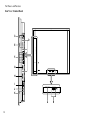
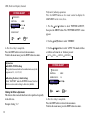
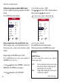
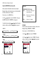
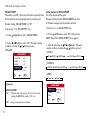
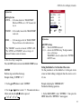
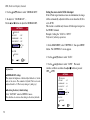
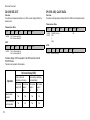
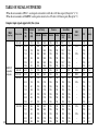
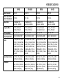
1
VP-42 / VP-42HD / VP-50 / VP-60
Owner’s Manual
TABLE OF CONTENTS
Introduction ............................................................................
Important Information ..........................................................
Limited Warranty ..................................................................
How to Attach Options to the Plasma Monitor ....................
Part Names and Functions ....................................................
Front View .............................................................................
Rear View / Terminal Board ..................................................
Remote Control .....................................................................
Battery Installation and Replacement ...................................
Handling the Remote Control ...............................................
Operating Range ...................................................................
Installation ..............................................................................
Connecting Your Computer ...................................................
Connecting Your VCR or Laser Disk Player .........................
Connecting Your DVD Player ...............................................
Pin Assignments/Signal Levels for 15-pin RGB (analog) ....
Pin Configuration/Signal of the RGB 3-In Connector (DVI
Connector) .............................................................................
Basic Operations ....................................................................
Power ....................................................................................
Volume ..................................................................................
Mute ......................................................................................
Display ..................................................................................
Timer Off ..............................................................................
Aspect Ratio Controls ............................................................
Aspect Ratio Operations (Manual) ........................................
Wide Screen Operation with Computer Signals ...................
2
4
8
11
12
12
13
15
17
18
18
19
20
21
21
22
22
23
23
23
23
23
24
25
25
27
OSD (On Screen Display) Controls ...................................... 28
Menu Operations ................................................................... 28
Picture Adjust Menu ............................................................. 33
Audio Setup Menu ................................................................ 40
Image Options Settings Menu ............................................... 42
SETTING 1 Menu ................................................................. 44
SETTING 2 Menu ................................................................. 50
SETTING 3 Menu ................................................................. 60
Language Settings Menu ....................................................... 76
Video Standard Menu ............................................................ 77
Signal Info. Menu ................................................................. 78
External Controls ................................................................... 79
Application ............................................................................ 79
Connections ........................................................................... 79
Communication Parameters .................................................. 79
Communication Format ........................................................ 79
Command Reference List ..................................................... 81
Table of Signals Supported .................................................. 106
Troubleshooting .................................................................... 109
Specifications ........................................................................ 111
Dimensions ............................................................................ 112
1
INTRODUCTION
» Introduction to the Vidikron PlasmaView™
VP-42 / VP-42HD / VP-50 / VP-60 Flat Panel Display Monitor
Vidikron presents a full line-up of high performance plasma display monitors, perfect for every application. Three models, 42, 50 and
60 inch, all share common style, engineering and design, features and state-of-the-art performance.
These three popular sizes all feature HDTV capable, 16:9 native resolution display panels with advanced engineering innovations to
give you the brightest, clearest images possible. Vidikron’s superior video processing with 3:2 film detection circuitry is built into
the monitors and provides exceptional detail and artifact-free video enhancement, elevating even standard NTSC material to near HD
quality.
Multiple aspect ratio control includes Vidikron’s IntelliWide mode, offering the ability to view standard video formats in widescreen
without loss of image quality. IR and discrete RS-232 controls facilitate glitch-free custom installation, while Dynamic Pixel
Protection™ helps to protect the plasma panel from stationery image burn.
A generous number of inputs and the sleekest styling around make these flat panel display monitors a great value and the ideal choice
for discerning viewers.
2
Introduction
» The features you’ll enjoy include:
• 16:9 Native Resolution:
853 x 480 (VP-42)
1024 x 768 (VP-42HD)
1365 x 768 (VP-50, VP-60)
• DVI Input with HDCP
• IR and discrete RS-232 Control for custom installation integration
• Dynamic Pixel Protection™ to help prevent stationary image burn
• HDTV Ready
• Less than 5 inches thin
Options:
• Wall mount unit
• Tilt mount unit
• Tablestand
Contents of the package:
• Plasma display monitor
• Power cord
• Remote control with two AAA batteries
• User’s manual
• Safety metal fittings*
• Screws for safety metal fittings*
• Ferrite core (small x 2. large x 2), bands
• Cable clamps
* These are fittings for fastening the unit to a wall to prevent tipping
due to external shock when using the tablestand (optional). Fasten
the safety fittings to the holes in the back of the plasma using the
safety fitting mount screws.
3
IMPORTANT INFORMATION
» Precautions
WARNING
Please read this manual carefully before using your plasma
monitor and keep the manual handy for future reference.
CAUTION
RISK OF ELECTRIC SHOCK
DO NOT OPEN
!
CAUTION: TO REDUCE THE RISK OF
ELECTRIC SHOCK, DO NOT REMOVE
COVER. NO USER-SERVICEABLE PARTS
INSIDE. REFER SERVICING TO QUALIFIED
SERVICE PERSONNEL.
This symbol warns the user that uninsulated
voltage within the unit may have sufficient
magnitude, it is dangerous to make any kind of
contact with any part inside this unit.
This symbol alerts the user that important
literature concerning the operation and
maintenance of this unit has been included.
Therefore, it should be read carefully in order to
avoid any problems.
4
TO PREVENT FIRE OR SHOCK HAZARDS, DO NOT
EXPOSE THIS UNIT TO RAIN OR MOISTURE. ALSO DO
NOT USE THIS UNIT’S POLARIZED PLUG WITH AN
EXTENSION CORD RECEPTACLE OR OTHER OUTLETS,
UNLESS THE PRONGS CAN BE FULLY INSERTED.
REFRAIN FROM OPENING THE CABINET AS THERE
ARE HIGH-VOLTAGE COMPONENTS INSIDE. REFER
SERVICING TO QUALIFIED SERVICE PERSONNEL.
WARNING
This equipment has been tested and found to comply with the
limits for a Class B digital device, pursuant to Part 15 of the FCC
Rules. These limits are designed to provide reasonable protection
against harmful interference when the equipment is operated
in a commercial environment. This equipment generates, uses,
and can radiate radio frequency energy and, if not installed
and used in accordance with the instruction manual, may cause
harmful interference to radio communications. Operation of
this equipment in a residential area is likely to cause harmful
interference in which case the user will be required to correct the
interference at his own expense.
Important Information
» Warnings and Safety Precautions
No maintenance other than cleaning is required. Please see the section “Plasma monitor cleaning procedure” on page 7.
The plasma display panel consists of fine picture elements (cells). There may be some cells that do not produce light or remain lit.
For operating safety and to avoid damage to the unit, read carefully and observe the following instructions. To avoid shock and fire
hazards:
1. Provide adequate space for ventilation to avoid internal heat build-up. Do not cover rear vents or install the unit in a closed cabinet or
shelves. If you install the unit in an enclosure, make sure there is adequate space at the top of the unit to allow hot air to rise and escape.
If the monitor becomes too hot, the overheat protector will be activated and the monitor will be turned off. If this happens, turn off the
power to the monitor and unplug the power cord. If the room where the monitor is installed is particularly hot, move the monitor to a
cooler location, and wait for 60 minutes to cool the monitor. If the problem persists, contact your dealer for service.
2. Do not use this unit’s polarized plug with extension cords or outlets unless the prongs can be completely inserted.
3. Do not expose the unit to water or moisture.
4. Avoid damage to the power cord, and do not attempt to modify the power cord.
5. Unplug the power cord during electrical storms or if the unit will not be used over a long period.
6. Do not open the cabinet which has potentially dangerous high voltage components inside. If the unit is damaged in this way the
warranty will be void. Moreover, there is a serious risk of electric shock.
7. Do not attempt to service or repair the unit. The manufacturer is not liable for any bodily harm or damage caused if unqualified persons
attempt service or open the back cover. Refer all service to authorized Service Centers.
5
Important Information
NOTE:
When you connect a computer to this monitor, use an RGB cable
including the ferrite core on both ends of the cable. And regarding
DVI and power cable, attach the supplied ferrite cores. If you do not
do this, the monitor will not conform to mandatory FCC standards.
Attaching the ferrite cores: Set the ferrite cores on both ends of
the DVI cable (not supplied), and both ends of the power cable
(supplied). Close the lid tightly until the clamps click. Use the
band to fasten the ferrite core (supplied) to the DVI cable.
» To avoid damage and prolong operating life:
DVI cable (not supplied)
4. Protect the inside of the unit from liquids and small metal
objects. In case of accident, unplug the power cord and have it
serviced by an authorized Service Center.
band
core (small)
Power cable (supplied)
core (large)
band
Connector
1. Use only with 120V 50/60Hz AC power supply. Continued
operation at line voltages greater than 120 Volts AC will shorten
the life of the unit, and might even cause a fire hazard.
2. Handle the unit carefully when installing it and do not drop.
3. Set the unit away from heat, excessive dust, and direct sunlight.
core (small)
5. Do not hit or scratch the panel surface as this causes flaws on
the surface of the screen.
core (large)
6. For correct installation and mounting it is strongly recommended
to use a trained, authorized dealer.
7. As is the case with any phosphor-based display (like a CRT
monitor, for example) light output will gradually decrease over
the life of a Plasma Display Panel.
8. To avoid sulfurization it is strongly recommended not to place
the unit in a dressing room in a public bath or hot spring bath.
6
Important Information
» Plasma monitor cleaning procedure:
* Change the position of the menu display from time to time.
1. Use a soft dry cloth to clean the front panel and bezel area.
Never use solvents such as alcohol or thinner to clean these
surfaces.
* Always power down the monitor when you are finished using
it.
If the plasma monitor is in long term use or continuous operation
take the following measures to reduce the likelihood of phosphor
burn:
2. Clean plasma ventilation areas with a vacuum cleaner with a
soft brush nozzle attachment.
3. To ensure proper ventilation, cleaning of the ventilation areas
must be carried out monthly. More frequent cleaning may be
necessary depending on the environment in which the plasma
monitor is installed.
* Lower the Brightness and Contrast levels as much as possible
without impairing image readability.
* Display an image with many colors and color gradations (i.e.
photographic or photo-realistic images).
Recommendations to avoid or minimize phosphor burn-in:
Like all phosphor-based display devices and all other gas plasma
displays, plasma monitors can be susceptible to phosphor burn
under certain circumstances. Certain operating conditions, such
as the continuous display of a static image over a prolonged
period of time, can result in phosphor burn if proper precautions
are not taken. To protect your investment in this plasma monitor,
please adhere to the following guidelines and recommendations
for minimizing the occurrence of image burn:
* Create image content with minimal contrast between light and
dark areas, for example white characters on black backgrounds.
Use complementary or pastel color whenever possible.
* Always enable and use your computer’s screen saver function
during use with a computer input source.
Contact your dealer for other recommended procedures that will
best suit your particular application needs.
* Display a moving image whenever possible.
* Avoid displaying images with few colors and distinct, sharply
defined borders between colors.
NOTE: BURN-INS ARE NOT COVERED BY THE
WARRANTY
7
LIMITED WARRANTY
Congratulations on your purchase of a Vidikron video product and
welcome to the Vidikron family! With proper installation, setup
and care, you should enjoy many years of unparalleled video
performance. This is a LIMITED WARRANTY as defined in the
Magnuson-Moss Warranty Act. Please read it carefully and retain it
with your other important documents.
WHAT IS COVERED UNDER THE TERMS OF THIS
LIMITED WARRANTY:
SERVICE LABOR: Vidikron will pay for service labor by a Vidikron
Authorized Service Center when needed as a result of manufacturing
defect for a period of one (1) year from the effective date of delivery
to the end user.
PARTS: Vidikron will provide new or rebuilt replacement parts for
the parts that fail due to defects in materials or workmanship for a
period of one (1) year from the effective date of delivery to the end
user. Such replacement parts are then subsequently warranted for the
remaining portion (if any) of the original warranty period.
8
WHAT IS NOT COVERED UNDER THE TERMS OF THIS
LIMITED WARRANTY:
Image burn-in on plasma display panels are specifically excluded
from coverage under this Limited Warranty. Image burn-in is the
result of misuse of the product and therefore cannot be repaired
under the terms of this Limited Warranty.
TO AVOID IMAGE BURN-IN:
Please ensure that still images are left on your plasma display panel
for no more than a few minutes. Also ensure that images displayed
in the 4:3 aspect ratio mode (black or gray stripes, but no picture
information is present on the left and right edges of the screen) are
used as infrequently as possible. This will prevent permanent image
burns on your plasma display panel, which can be seen permanently
under certain conditions once burn-in has occurred.
The types of images to avoid include video games, still images and
computer screens with stationary tool bars and icons. (This is why
computers are equipped with screen savers – to prevent still images
from burning into the monitor’s phosphors after being displayed
continuously for an extended period of time).
Normal viewing material such as television/satellite broadcasts,
videotape or DVDs (not put into pause for extended periods of time)
will not cause damage to your display under normal conditions.
Many DVD players are also equipped with screen savers for this
reason.
This Limited Warranty only covers failure due to defects in materials
and workmanship that occur during normal use and does not cover
normal maintenance. This Limited Warranty does not cover cabinets
or any appearance items; failure resulting from accident, misuse,
abuse, neglect, mishandling, misapplication, faulty or improper
installation or setup adjustments; improper maintenance, alteration,
improper use of any input signal; damage due to lightning or power
line surges, spikes and brownouts; damage that occurs during
shipping or transit; or damage that is attributed to acts of God. In the
case of remote control units, damage resulting from leaking, old,
Limited Warranty
damaged or improper batteries is also excluded from coverage under
this Limited Warranty.
CAUTION: THIS LIMITED WARRANTY ONLY COVERS
VIDIKRON PRODUCTS PURCHASED FROM VIDIKRON
AUTHORIZED DEALERS. ALL OTHER PRODUCTS ARE
SPECIFICALLY EXCLUDED FROM COVERAGE UNDER
THIS LIMITED WARRANTY. MOREOVER, DAMAGE
RESULTING DIRECTLY OR INDIRECTLY FROM IMPROPER
INSTALLATION OR SETUP IS SPECIFICALLY EXCLUDED
FROM COVERAGE UNDER THIS LIMITED WARRANTY.
RIGHTS, LIMITS AND EXCLUSIONS:
Vidikron limits its obligations under any implied warranties under
state laws to a period not to exceed the warranty period. There are no
express warranties. Vidikron also excludes any obligation on its part
for incidental or consequential damages related to the failure of this
product to function properly. Some states do not allow limitations
on how long an implied warranty lasts, and some states do not allow
the exclusion or limitation of incidental or consequential damages.
So the above limitations or exclusions may not apply to you. This
warranty gives you specific legal rights, and you may also have other
rights that vary from state to state.
EFFECTIVE WARRANTY DATE:
This warranty begins on the effective date of delivery to the end
user. For your convenience, keep the original bill of sale as evidence
of the purchase date.
IMPORTANT: WARRANTY REGISTRATION:
Please fill out and mail your warranty registration card. It is
imperative that Vidikron knows how to reach you promptly if we
should discover a safety problem or product update for which you
must be notified.
CONTACT A VIDIKRON AUTHORIZED SERVICE CENTER
TO OBTAIN SERVICE:
Repairs made under the terms of this Limited Warranty covering
your Vidikron video product will be performed at the location of the
product, during usual working hours, providing location of product
is within normal operating distance from a Vidikron Authorized
Service Center. In some instances it may be necessary for the
product to be returned to the Vidikron factory for repairs. If, solely
in Vidikron’s judgment, location of product to be repaired is beyond
normal operating distance of the closest Vidikron Authorized Service
Center, or the repair requires the unit be returned to the Vidikron
factory, it is the owner’s responsibility to arrange for shipment of
the product for repair. These arrangements must be made through
the selling Vidikron dealer. If this is not possible, contact Vidikron
directly to locate an authorized Vidikron representative who will
assist you in getting a return authorization. Vidikron will return
product transportation prepaid in the United States, unless no
product defect is discovered. In that instance, shipping costs will be
the responsibility of the owner.
9
Limited Warranty
ADDITIONAL INFORMATION:
To locate the name and address of the nearest VIDIKRON authorized service location, or for additional information about this Limited
Warranty, please call or write:
VIDIKRON
Attn: Customer Service Department
2900 Faber Street
Union City, CA 94587
Ph (510) 324-5900
Fax (510) 324-5905
Toll Free 1-888-4-VIDIKRON
10
HOW TO ATTACH OPTIONS TO THE PLASMA MONITOR
You can attach your optional mounts or stand to the
plasma monitor in one of the following two ways:
1) While it is upright. (See drawing A)
2) As it is laid down with the screen face down (See
drawing B). Lay the protective sheet, which was
wrapped around the plasma monitor when it was
packaged, beneath the screen surface so it does not
scratch the screen face.
B
A
* DO NOT touch or hold the screen face when
carrying the unit.
• For correct installation and mounting, it is required
to use a trained, Vidikron Authorized Dealer. Failure
to follow correct mounting procedures could result
in damage to the equipment or injury to the installer.
Product warranty does not cover damage caused by
improper installation.
Use only the mounting kit or stand provided
by Vidikron. Refer to mounting kit for detailed
instructions.
50mm (2")
50mm (2")
50mm (2")
Wall
50mm (2")
• This device cannot be installed on its own. Be sure
to use a stand or original mounting unit. (wallmount
unit, stand, etc.)
Wall
50mm (2")
Ventilation Requirements for enclosure mounting
To allow heat to disperse, leave space between surrounding
objects as shown on the diagram to the right when installing.
11
PART NAMES AND FUNCTIONS
» Front View
1
POWER
Turns the plasma monitor’s power on and off.
2
REMOTE SENSOR WINDOW
Receives the signals from the remote control.
3
POWER
When the power is on it will light GREEN. When the power is on
the standby mode, it will light RED.
4
INPUT SELECT / EXIT
Switches the input, in the following order. The available inputs
depend on the setting of “BNC INPUT”.
RGB:
COMP:
12
Located on bottom
of Plasma
MENU / ENTER
VIDEO1 VIDEO2 VIDEO3 HD/COMP/DTV
RGB/PC3 RGB/PC2 RGB/PC1
7
VOLUME
DOWN
UP
6
Located on bottom
of Plasma
LEFT/-
RIGHT/+
5
INPUT SELECT
/EXIT
4
1
3
2
VIDEO1 VIDEO2 VIDEO3 HD1/COMP1/DTV1
RGB/PC2 RGB/PC1 HD2/COMP2/DTV2
5
LEFT/- and RIGHT/+
Enlarges or reduces the image. Functions as the CURSOR ( / )
buttons in the On-Screen Display (OSD) mode.
6
VOLUME DOWN and UP
Adjusts the volume. Functions as the CURSOR ( / ) buttons in
the On-Screen Menu mode.
7
MENU
Sets the On-Screen Menu mode and displays the main
menu.
Part Names and Functions
» Rear View / Terminal Board
A
AC IN
Connect the included power cord here.
B
C
G
RGB1 (mini D-Sub 15pin)
Connect an analog RGB signal from a computer, etc. here.
This input can be used for Input or Output.
Connect speakers (not available from Vidikron) here.
Maintain the correct polarity.
H
VIDEO 1,2,3 (BNC, RCA, S-Video)
Connect VCR’s, DVD’s or Video Cameras, etc here.
VIDEO1 can be used for INPUT or OUTPUT.
RGB3 (DVI 24pin)
Connect a digital signal (TMDS) from a source with a DVI
output.
I
EXTERNAL CONTROL
This terminal is used when operating and controlling the
monitor externally by RS-232.
D
AUDIO1, AUDIO2, AUDIO3
These are audio input terminals. The input is selectable.
Set which video image to distribute them from the audio
menu screen.
E
DVD1 / HD1
Connect DVD’s, High Definition or Laser Disks, etc here.
F
RGB2 / DVD2 / HD2
RGB2: Connect an analog RGB signal and the
synchronization signal.
DVD2 / HD2: Connect DVD’s, High Definition sources,
Laser Discs, etc. here. This input can be set for use with an
RGB or Component source.
13
Part Names and Functions
Rear View / Terminal Board
VIDEO 2
(MONO)
L
Y
Cb/Pb
Cr/Pr
DVD1 / HD1
(MONO)
L
AUDIO 2
R
R/
Cr/Pr
B/
Cb/Pb
HD
RGB2 / DVD2 / HD2
G/
Y
VD
RGB 1
(I N / OUT)
G
D
AUDIO 1
R
(MONO)
L
RGB 3
DV I ( Digital RGB )
External Control
IN
REMOTE
OUT
B
A
SPEAKERS MUST
HAVE MORE THAN
7WATT RATING
IMPEDANCE 6 OHM
LEFT
RIGHT
IN
SPEAKERS MUST
HAVE MORE THAN
7WATT RATING
IMPEDANCE 6 OHM
LEFT
RIGHT
IN
AC
AUDIO 3
R
14
VIDEO 3
F
AC
I
J
K
(IN/OUT)
H
VIDEO 1
E
VIDEO
C
Part Names and Functions
» Remote Control
1
ON/OFF
Switches Power ON/OFF. (This does not operate when
POWER/STANDBY indicator of the main unit is off.
2
CURSOR ( / / / )
Use these buttons to select items or settings and to adjust
settings or switch the display patterns.
3
4
5
6
EXIT
Press this button to exit the OSD controls in the main menu.
Press this button during the display of the sub menu
to return to the previous menu.
MENU
Press this button to access the OSD controls. Press this
button during the display of the main menu to go to the sub
menu.
VID 1-2-3
Press this button to select VIDEO as the source.
VID1 VID2 VID3
VIDEO can also be selected using the INPUT SELECT
button on the monitor.
COMP 1-2
Press this button to select between Component 1 and
Component 2 inputs.
7
RGB 1-2-3
Press this button to select RGB/PC as the source. The
available sources depend on the setting of “BNC INPUT”.
RGB:
RGB1 RGB2 RGB3
COMP:
RGB1
RGB3
RGB can also be selected using the INPUT SELECT
button on the monitor.
8
ASPECT
Press this button to select between aspect ratios.
9
MUTE
Mutes the sound.
10
VOLUME (+/-)
Adjusts the audio volume.
11
AUTO OFF
Use to select AUTO OFF TIMER settings.
15
Part Names and Functions
Remote Control (continued)
12
DISPLAY
Displays the source settings on the screen.
13
LIGHT*
Press this to illuminate the buttons.
* Not available on all models.
1
2
3
4
6
5
7
9
8
10
11
12
16
13
Part Names and Functions
» Battery Installation and Replacement
Insert the 2 “AAA” batteries, making sure to
set them in with the proper polarity.
1. Press and open the cover.
2. Align the batteries according to the (+) and
(–) indication inside the case.
3. Replace the cover.
17
Part Names and Functions
» Handling the remote control
• Do not drop or mishandle the remote control.
• Do not get the remote control wet. If the remote control gets wet,
wipe it dry immediately.
• Avoid heat and humidity.
• When not using the remote control for a long period, remove the
batteries.
• Do not use new and old batteries together, or use different types
together.
• Do not take apart the batteries, heat them, or throw them into a
fire.
» Operating Range
* Use the remote control within a distance of about 23 ft. (7m)
from the front of the monitor’s remote control sensor and at
horizontal an vertical angles of up to approximately 30°.
* The remote control operation may not function if the monitor’s
remote control sensor is exposed to direct sunlight or strong
artificial light, or if there is an obstacle between the sensor and
the remote control.
Approx.
23 ft (7m)
18
INSTALLATION
VCR or Laser Disc Player
VIDEO
VIDEO 1
(I N/ OUT)
VIDEO 1-3
VIDEO 2
VIDEO 3
To video inputs on
the plasma monitor
AUDIO 1
R
(MONO)
L
Y
DVD1 / HD1
Cb/Pb
Cr/Pr
AUDIO 2
R
(MONO)
L
R/
Cr/Pr
B/
Cb/Pb
HD
RGB 2 / DVD2 / HD2
G/
Y
DVD Player
VD
IBM VGA or Compatibles
RGB 1
(I N / OUT )
AUDIO 3
R
(MONO)
Macintosh or Compatibles
L
(Desktop type)
RGB 3
DV I ( Digital RGB )
External Control
Monitor adapter for
Macintosh
IN
To Mini D-Sub 15 pin connector on the plasma monitor
REMOTE
OUT
HD Set Top Box with DVI
HDCP Output, Computer,
other devices
19
Installation
» Connecting Your PC or Macintosh Computer
Connecting your PC or Macintosh computer to your plasma
monitor will enable you to display your computer’s screen image
for an impressive presentation. The plasma monitor supports the
signals described on page 106.
5. Turn on the plasma monitor and the computer.
To connect a PC, Macintosh or compatible graphics adapter,
simply:
When using a Macintosh with the plasma monitor, the
following four display standards are supported using the
Macintosh adapter:
13” fixed mode
16” fixed mode
19” fixed mode
21” fixed mode
The 13” fixed mode is recommended for your 42” Wide VGA.
1. Turn off the power to your plasma monitor and computer.
2. If your PC does not support SXGA/XGA/SVGA/VGA you
will need to install an SXGA/XGA/SVGA/VGA graphics
board. Consult your computer’s owner’s manual for your SXGA/
XGA/SVGA/VGA configuration. If you need to install a new
board, see the manual that comes with your new graphics board
for installation instructions.
3. This plasma monitor provides signal compatibility up to VESA
1600 x 1200 (UXGA). However, it is not recommended to use
this resolution due to image readability on the monitor’s native
pixel resolution panel.
4. Use the signal cable to connect your PC or Macintosh computer
to the plasma monitor. For Macintosh, use the monitor adapter to
connect to your computer’s video port, if necessary.
20
6. If the plasma monitor goes blank after a period of inactivity, it
may be caused by a screen saver installed on the computer you’ve
connected to the plasma monitor.
Installation
» Connecting Your VCR or Laser Disc Player:
Use common RCA cables (not provided) to connect your VCR
or laser disc player to your plasma monitor. To make these
connections, simply:
» Connecting Your DVD Player:
You can connect your plasma monitor to a DVD player. To do
so, simply:
1. Turn off the power to your plasma monitor and DVD player.
1. Turn off the power to your plasma monitor and VCR or laser
disc player.
2. Connect one end of your RCA cable to the video output
connector on the back of your VCR or laser disc player, connect
the other end to the Video input on your plasma monitor. Use
standard RCA audio patch cords to connect the audio from your
VCR or laser disc player to your plasma monitor (if your VCR or
laser disc player has this capability). Be careful to keep your right
and left channel connections correct for stereo sound.
2. Use a component video cable to connect your DVD player
to the Y, Cb, and Cr inputs on your plasma monitor. Or use
the DVD-player’s S-Video output. Use a standard S-Video
cable to connect to the S-Video input on the plasma monitor.
3. Turn on the plasma monitor and the DVD player.
3. Turn on the plasma monitor and the VCR or laser disc player.
Note: Refer to your VCR or laser disc player owner’s
manual for more information about your equipment’s
video output requirements.
21
Installation
» Pin Assignment and Signal Levels for 15 pin RGB (analog)
5
4 3 2 1
10 9 8 7 6
15 14 13 12 11
» Pin Configuration and Signal of the RGB 3 Connector (DVI
Connector)
The unit is equipped with a type of connector commonly used for
digital. (This cannot be used for an analog input.)
RGB 3
Pin No.
1
2
3
4
5
6
7
8
9
10
11
12
13
14
15
22
Signal (Analog)
Red
Green or sync-on-green
Blue
No connection
Ground
Red ground
Green ground
Blue ground
No connection
Sync signal ground
No connection
Bi-directional DATA (SDA)
Horizontal sync or Composite sync
Vertical sync
Data clock
1 2 3 4 5 6 7 8
9 10 11 12 13 14 15 16
17 18 19 20 21 22 23 24
Pin No.
1
2
3
4
5
6
7
8
9
10
11
12
Signal (Digital)
T.M.D.S Data 2 T.M.D.S Data 2 +
T.M.D.S Data 2 Shield
No connection
No connection
DDC Clock
DDC Data
No connection
T.M.D.S Data 1 T.M.D.S Data 1 +
T.M.D.S Data 1 Shield
No connection
Pin No.
13
14
15
16
17
18
19
20
21
22
23
24
Signal (Digital)
No connection
+5V Power
Ground
Hot Plug Detect
T.M.D.S Data 0 T.M.D.S Data 0 +
T.M.D.S Data Shield
No connection
No connection
T.M.D.S Clock Shield
T.M.D.S Clock +
T.M.D.S Clock -
BASIC OPERATIONS
» POWER
» DISPLAY
To turn the unit ON and OFF:
1. Plug the power cord into an active AC power outlet.
To check the settings:
1. The screen changes each time the DISPLAY button is pressed.
2. If the button is not pressed for approximately three seconds, the
menu turns off.
2. Press the POWER ON button (on the remote control or control
panel) to turn on the unit.
The monitor’s POWER/STANDBY indicator will light up (green)
when the unit is on.
3. Press the POWER OFF button (on the remote control or control
panel) to turn off the unit.
The monitor’s POWER/STANDBY indicator turns red and the
standby mode is set (only when turning off the unit with the
remote control).
» VOLUME
To adjust the sound volume:
1. Press and hold the VOLUME (+) button (on the remote control
or the unit) to increase to the desired level.
2. Press and hold the VOLUME (-) button (on the remote control
or the unit) to decrease to the desired level.
» MUTE
To cancel the sound:
Press the MUTE button on the remote control to cancel the sound;
press again to restore.
23
Basic Operations
» TIMER OFF
To set the timer off:
The timer off can be set to turn the power off after 30, 60, 90 or
120 minutes
To cancel the off timer:
1. Press the AUTO OFF button twice in a row.
2. The off timer is canceled.
TIMER OFF
30
1. Press the AUTO OFF button to start the timer at 30 minutes.
2. Press the AUTO OFF button to the desired time.
3. The timer starts when the menu turns off.
30 60 90 120 0 ┐
└─────────────────
TIMER OFF
30
To check the remaining time:
1. Once the off timer has been set, press the AUTO OFF button
once.
2. The remaining time is displayed, then turns off after a few
seconds.
3. When five minutes remain the remaining time appears until it
reaches zero.
TIMER OFF
24
30
NOTE:
After the power is turned off with the timer off...
A slight current is still supplied to the monitor. When you are
leaving the room or do not plan to use the system for a long period
of time, turn off the power of the monitor.
ASPECT RATIO CONTROLS
» Aspect Ratio Operations (Manual)
STD 4:3 mode
There are four aspect ratios available that can be selected for
video signal inputs.
The input signal will be scaled to fit in the center of the 16:9
screen.
When viewing videos or DVDs:
1. Press the ASPECT button on the remote control.
2. Within 3 seconds...
Press the ASPECT button again.
The screen size switches as follows:
LTR BOX
STD (4:3)
ANAMPHC
Active
Image
Area
INTELLIWIDE
LTR BOX mode
The image in the Letterbox mode will be zoomed in, and the top
and bottom portion ‘blanked off.’ This ratio is best suited for
LaserDisc movies or non-anamorphic DVD’s.
Active Image Area
ANAMPHC mode
The image is compressed vertically, but anamorphic software
will appear properly proportioned.
This is best suited for use with 16:9 DVD’s.
Active Image Area
25
Aspect Ratio Controls
INTELLIWIDE mode
This aspect ratio is designed to fill the 16:9 screen with a 4:3
image. The center of the picture is not stretched, and it gradually
stretches on the sides reaching the most extreme stretch at the far
edges of the picture. (non-linear scaling)
In addition, we apply a very slight vertical stretch uniformly (no
graduation) which results in a very small amount of cropping of
the top and bottom of the image area.
Thus a 4:3 image is transformed into a 16:9 image with minimal
distortion.
Active
Image
Area
26
Aspect Ratio Controls
» Aspect Ratio Operation with Computer Signals
Switch to the wide screen mode to expand the 4:3 image to fill the
entire screen.
1. Press the ASPECT button on the remote control.
2. Within 3 seconds...
Press the ASPECT button again.
The screen size switches as follows:
STD (4:3)
ANAMPHC
LTR BOX
STD 4:3 mode (4:3 or SXGA 5:4)
Active
Image
Area
The picture has the same size as the normal computer image.
ANAMPHC mode
Active Image Area
The image is expanded in the horizontal direction.
LTR BOX mode
Active Image Area
When wide signals are input.
Information
■ Supported resolution
See page 106 for details on the display output of the
various VESA signal standards supported by the monitor.
■ When 853 (848) dot x 480 line wide VGA *signals
with a vertical frequency of 60 Hz and horizontal
frequency of 31.7 (31.0) kHz are input.
Select an appropriate setting for RGB SELECT mode
referring to the “Table of Signals Supported” on page
106.
* “IBM PC/AT” and “VGA” are registered trademarks of
IBM, Inc. of the United States.
NOTE:
Do not leave the displayed in 4:3 mode for an extended period.
This can cause a phosphor burn-in.
27
OSD (On Screen Display) Controls
» Menu Operations
The OSD window is displayed with respect to the screen as shown
on the diagram.
3. Press the cursor buttons
on the
remote control to highlight the menu
you wish to enter.
PICTURE ADJUST
0
BRIGHTNESS
0
SHARPNESS
0
COLOR
* Depending on the screen’s mode, the OSD may be displayed
differently. In the explanation, the OSD section is shown close
up.
The following describes how to use the menus and the selected
items.
PLASMAVIEW
1. Press the MENU button on
the remote control to display
the MAIN MENU.
IMAGE OPTIONS
SETTING 1
SETTING 2
SETTING 3
MENU/ENTER
OK
EXIT
EXIT
PLASMAVIEW
1/2
LANGUAGE
IMAGE OPTIONS
VIDEO STANDARD
SETTING 1
2/2
SIGNAL INFO.
SETTING 2
SETTING 3
SEL.
NEXT PAGE
EXIT
VIDEO NR
:
OFF
NEXT PAGE
4. Adjust the level or change the setting of the selected item by
using the cursor buttons ◄► on the remote control.
NOTE:
The main menu disappears by pressing the EXIT button.
PREVIOUS PG.
OK
FACTORY
6. Repeat steps 2-5 to adjust an additional item, or press the EXIT
button on the remote control to return to the main menu.
AUDIO SETUP
MENU/ENTER
:
NEXT PAGE
PICTURE ADJUST
SEL.
0
IMAGE MEM.
5. Change the adjustments or the settings that are stored in
memory. The change is stored until you change it again.
AUDIO SETUP
2. Press the MENU button on the remote control to select a
submenu or item.
28
0
TINT
1/2
PICTURE ADJUST
SEL.
PLASMAVIEW
1/2
CONTRAST
EXIT
MENU/ENTER
OK
EXIT
EXIT
OSD (On Screen Display) Controls
Main Menu
Sub Menu
Functions
Default
Reset
PICTURE
ADJUST
CONTRAST
Adjusts the contrast.
Center
Yes
BRIGHTNESS
Adjusts the brightness.
Center
Yes
SHARPNESS
Adjusts the sharpness
Center
Yes
COLOR
Adjusts the color.
Center
Yes
TINT
Adjusts the tint.
Center
Yes
IMAGE MEM.
Sets the image memory according to the VIDEO environment and image S/W.
CONTRAST
Yes
VIDEO NR
Reduces noise visible in image.
OFF
Yes
WHITE BAL.
Adjusts the color temperature and white balance.
8500K
Yes
GAIN RED
Adjusts the red content (signal level).
Center
Yes
GAIN GREEN
Adjusts the green content (signal level).
Center
Yes
GAIN BLUE
Adjusts the blue content (signal level).
Center
Yes
RED OFFSET
Adjusts the red content (black level).
Center
Yes
GREEN OFFSET
Adjusts the green content (black level).
Center
Yes
BLUE OFFSET
Adjusts the blue content (black level).
Center
Yes
RESET
WHITE
BALANCE
ADJUST
Resets the WHITE BALANCE ADJUST settings to the factory default values.
OFF
Yes
GAMMA CURVE
Adjusts the brightness of midtone areas.
2.2
Yes
DITHER
Enables high-quality dark area reproduction.
AUTO
Yes
RED
Adjusts hue and color density of red.
Center
Yes
GREEN
Adjusts hue and color density of green.
Center
Yes
BLUE
Adjusts hue and color density of blue.
Center
Yes
YELLOW
Adjusts hue and color density of yellow.
Center
Yes
MAGENTA
Adjusts hue and color density of magenta.
Center
Yes
CYAN
Adjusts hue and color density of cyan.
Center
Yes
RESET
Resets COLOR CHART settings to the factory default values.
OFF
Yes
COLOR CHART
29
OSD (On Screen Display) Controls
30
Main Menu
Sub Menu
Functions
Default
Reset
AUDIO SETUP
BASS
Sets the bass.
Center
Yes
TREBLE
Sets the treble.
Center
Yes
BALANCE
Sets the left/right balance.
Center
Yes
AUDIO INPUT 1-3
Sets the allocation of the audio connectors.
*1
Yes
Main Menu
Sub Menu
Functions
Default
Reset
IMAGE
OPTIONS
ASPECT RATIO
Selects between the different aspect ratio modes.
--
--
V SHIFT
Adjusts the vertical position.
Center
Yes
H SHIFT
Adjusts the horizontal position.
Center
Yes
V-SIZE
Adjusts the vertical size.
Min
Yes
H-SIZE
Adjusts the horizontal size.
Min
Yes
COMPUTER
Turn this on to have the monitor automatically adjust “FINE PICTURE” and
“PICTURE ADJ”
OFF *
No
FINE PICTURE
Adjusts for flickering on the computer image.
Min *2
Yes
PICTURE ADJUST
Adjusts for striped patterns on the computer image.
Center *2
Yes
Main Menu
Sub Menu
Functions
Defaults
Reset
SETTING 1
OSD
ON
Yes
1
Yes
DISPLAY OSD
When set to OFF, the on-screen menu is not displayed.
OSD ADJ.
Sets the position of the menu.
OSD POSITION
Sets the display format as a horizontal or vertical screen.
H
Yes
OSD ORBITER
Sets the OSD not to be displayed at the same position.
OFF
Yes
BNC INPUT
Sets the BNC connectors.
RGB
Yes
D-SUB TYPE
Checks the signal being transmitted to RGB1 terminal.
RGB TYPE
Sets the appropriate mode for the computer image.
RGB
--
AUTO
Yes
OSD (On Screen Display) Controls
Main Menu
Sub Menu
Functions
Default
Reset
RGB (VGA signals), VIDEO (Moving picture), WIDE (Wide VGA), DTV.
HD TYPE
Sets the digital broadcasting (1080A, 1080B, 1080C) or the High Vision (1035I).
INPUT SKIP
Skips over signals which are not present.
FACTORY
Resets all the settings (PICTURE ADJUST, AUDIO, IMAGE OPTIONS,
SETTING 1-3, etc.) to the factory default values.
Main Menu
Sub Menu
Functions
SETTING 2
AUTO OFF
Sets the monitor for use as an energy-saving display when used with a computer.
CINEMA MODE
PIXL PROTECT
Sets the picture to suit the movie.
1080B
No
OFF
Yes
--
--
Default
Reset
OFF
Yes
ON
Yes
AUTO
Yes
Moves the picture intermittently.
OFF
Yes
INVERSE
Displays a negative/positive inverse image or an all-white screen.
OFF
Yes
IMAGE SWEEP
Sweeps the screen with a white vertical bar.
OFF
Yes
SOFTEN
Softens the detail in 4 steps (1-4)
OFF
Yes
LUM. SETTING
Limits screen brightness to reduce burn-in on the display.
ORBITER
SIDEBAR LEV.
In case of 4:3, sets the luminance of both sides.
3
Yes
S1/S2
Resizes the S-video image to best fit the display.
OFF
Yes
Defaults
Reset
--
No
Main Menu
Sub Menu
SETTING 3
TIMER
Functions
PRESENT TIME
Sets the day of the week and the time.
PROGRAM
Sets the ON/OFF time for switching on the power and the input mode.
OFF
Yes
LAST
Yes
OFF
Yes
Disables the transmission of the remote control.
ON
Yes
When set to ON, the received signal will be looped out.
OFF
Yes
INPUT SELECT
Sets the input mode at the time the power is switched on.
CONTROL LOCK
Disables the function of the front panel buttons.
IR ENABLE
LOOP OUT
31
OSD (On Screen Display) Controls
Main Menu
Sub Menu
VIDEO WALL
Main Menu
Sub Menu
Default
Reset
ID NUMBER
Functions
Sets ID number for the display.
ALL
Yes
DIVIDER
Creates a 2x2 or 3x3 video wall.
OFF
Yes
POSITION
Sets the position.
--
--
DISP. MODE
Selects the screen mode from between Splitting and Blanking.
SPLIT
Yes
AUTO ID
Automatically sets the ID number of multiple displays.
OFF
Yes
IMAGE
ADJUST
Adjusts the position of the image, etc.
--
--
P. ON DELAY
When set to ON, each display turns on after a delay time.
OFF
Yes
LUM SET
LINK
Sets a uniform brightness for each display.
OFF
Yes
REPTR
TIMER
Sets two programmable timers.
OFF
Yes
Functions
Default
Reset
LANGUAGE
Sets the language of the menus (English, German, French, Italian, Spanish).
English
No
VIDEO
STANDARD
Sets the VIDEO format (AUTO, PAL, PAL-M, PAL-N, PAL60, SECAM, 4.43
NTSC or 3.59 NTSC).
AUTO
No
SIGNAL INFO.
Used to check the frequency and synchronizing polarities of the active signal
being input.
--
--
*1 AUDIO INPUT 1: VIDEO 1 AUDIO INPUT 2: HD/DVD1 AUDIO INPUT 3: RGB1
*2 RGB/PC only
32
OSD (On Screen Display) Controls
» Picture Adjust Menu
Adjusting the picture
The contrast, brightness, sharpness, color and tint can be adjusted
as desired.
Example: Adjusting the contrast
Press the MENU button on the remote control to display the
MAIN MENU on the screen, then...
1. Use the
and
buttons to select “PICTURE ADJUST”,
then press the MENU button. The “PICTURE ADJUST” screen
appears.
2. Use the and buttons to select “CONTRAST”.
PICTURE ADJUST
1/2
CONTRAST
0
BRIGHTNESS
0
SHARPNESS
0
COLOR
0
TINT
0
IMAGE MEM.
:
FACTORY
VIDEO NR
:
OFF
NEXT PAGE
3. Use the
and
buttons to adjust the contrast.
CONTRAST
0
* If neither or buttons is pressed within 5 seconds, the current
setting is set and the previous screen reappears.
4. Once the adjustment is completed...
Press the EXIT button to return to the main menu.
To delete the main menu, press the EXIT button once more.
NOTE:
If “CAN NOT ADJUST” appears...
When trying to enter the PICTURE submenu, make sure IMAGE
MEM. is not set to FACTORY.
Information
■ Picture adjustment screen
CONTRAST ......... Changes the picture’s white level.
BRIGHTNESS ..... Changes the picture’s black level.
SHARPNESS ....... Changes the picture’s sharpness.
Adjusts picture detail of VIDEO
display.
COLOR ................ Changes the color density.
TINT .................... Changes the picture’s tint. Adjust for
natural colored skin, background, etc.
■ Adjusting the computer image
Only the contrast and brightness can be adjusted when a
computer signal is connected.
■ Restoring the factory default settings
Select “FACTORY” under the “IMAGE MEM.” settings.
33
OSD (On Screen Display) Controls
Setting the picture mode according to the brightness of the
room
There are four picture modes that can be used effectively according
to the environment in which you are viewing the display.
3. To set to “FACTORY” ...
Use the
and
buttons to select “FACTORY”. The mode
switches as follows when the and buttons are pressed:
CONTRAST
LW BLK1
LW BLK2
FACTORY
BOOST
Example: Setting the “FACTORY” mode
Press the MENU button on the remote control to display the
MAIN MENU on the screen, then...
1. Use the
and
buttons to select “PICTURE ADJUST”,
then press the MENU button. The “PICTURE ADJUST” screen
appears.
2. Use the
and
buttons to select “IMAGE MEM.”
PICTURE ADJUST
0
BRIGHTNESS
0
SHARPNESS
0
COLOR
0
TINT
0
IMAGE MEM.
:
FACTORY
VIDEO NR
:
OFF
NEXT PAGE
34
1/2
CONTRAST
IMAGE MEM.
:
FACTORY
If neither the
or
button is pressed within 5 seconds, the
current selection is set and the previous screen reappears.
4. Once the adjustment is completed...
Press the EXIT button to return to the main menu. To delete the
main menu, press the EXIT button once more.
Information
■ Types of picture modes
LW BLK1, 2
Set this mode when watching video in a dark room. This mode
provides darker, finer pictures, like the screen in movie theaters. For a
darker image, select LW BLK2.
CONTRAST
Set this mode when watching video in a bright room. This mode
provides dynamic pictures with distinct differences between light and
dark sections.
BOOST
Use this setting to boost brightness.
FACTORY
Use this to reset the picture to the factory default settings.
OSD (On Screen Display) Controls
Reducing noise in the picture
Use these settings if the picture has noise due to poor reception
or when playing video tapes on which the picture quality is poor.
Example: Setting “VID NR-3”
Press the MENU button on the remote control to display the
MAIN MENU on the screen, then...
1. Use the
and
buttons to select “PICTURE ADJUST”,
then press the MENU button. The “PICTURE ADJUST” screen
appears.
2. Use the
and
buttons to select “VIDEO NR”.
�����������������������������
���������
�
��������������
�����������
�
��������������
����������
�
��������������
������ �
�
��������������
�����
�
��������������
�
�����������
���������������
���������
���������������
�����������������
3. Use the and buttons to select “VID NR3”.
The mode switches as follows when the
and
pressed:
OFF
VID NR
VID NR-1
VID NR-2
:
buttons are
VID NR-3
VID NR3
* If neither the or button is pressed within 5 seconds,
the current selection is set and the previous screen reappears.
4. Once the setting is completed...
Press the EXIT button to return to the main menu.
To delete the main menu, press the EXIT button once more.
Information:
■ VIDEO NR
* “NR” stands for Noise Reduction.
* This function reduces noise in the picture.
■ Types of noise reduction
There are three types of noise reduction. Each has a different
level of noise reduction. The effect becomes stronger as the
number increases (in the order VID NR1
VID NR2
VID NR3).
OFF ....... Turns the noise reduction function off.
35
OSD (On Screen Display) Controls
Setting the White Balance
Use this procedure to set color tone produced by the plasma display.
Example: Setting “6500K”
Press the MENU button on the remote control to display the
MAIN MENU on the screen, then...
1. Use the
and
buttons to select “PICTURE ADJUST”,
then press the MENU button. The “PICTURE ADJUST” screen
appears.
2. Use the
and
buttons to select “WHITE BAL”.
3. Use the and buttons to select “6500K”.
The mode switches as follows when the
and
pressed:
5400K
6500K
8500K
PICTURE ADJUST
PREVIOUS PG.
:
■ Restoring the factory default settings
Select “FACTORY” under the SETTING 1 menu. Note that
this also restores other settings to the factory defaults.
6500K
2/2
Adjusting the color to the desired level
Use this procedure to adjust the white balance for each color
temperature to achieve the desired color quality.
Example: Adjusting the “GAIN RED” of “9300K” color
temperature.
GAMMA CURVE :
2.2
Perform the following operations.
DITHER
AUTO
Press the MENU button on the remote control to display the
MAIN MENU on the screen, then...
:
COLOR CHART
SEL.
36
Information
■ Setting the color temperature
5400K .................... Redder
6500K .................... Slightly redder
8500K .................... Standard (slightly bluer)
9300K .................... Bluer
9300K
* See below to set “WHITE BALANCE ADJUST”.
WHITE BAL
buttons are
* If neither the or button is pressed within 5 seconds, the
current selection is set and the previous screen reappears.
4. Once the setting is completed...
Press the EXIT button to return to the main menu. To delete the
main menu, press the EXIT button once more.
ADJ.
EXIT EXIT
Perform Steps 1-3 of WHITE BAL., then...
OSD (On Screen Display) Controls
4. Press the MENU button. The “WHITE BAL.” screen appears.
5. Use the
and
buttons to select “GAIN RED”.
WHITE BALANCE ADJUST
Information
■ Adjusting the white balance
R/G/B GAIN ......... White balance adjustment for signal level
R/G/B OFFSET ......White balance adjustment for black level
RESET .................... Resets settings to the factory default
values. Use
and buttons to select
“ON”, then press the MENU button.
WHITE BAL. 6500K
GAIN RED
0
GAIN GREEN
0
GAIN BLUE
0
RED OFFSET
0
GREEN OFFSET
0
BLUE OFFSET
RESET
SEL.
0
:
ADJ.
OFF
EXIT EXIT
6. Adjust the white balance using the
GAIN RED
■ Restoring the factory default settings
Select “RESET” under the WHITE BAL. menu.
and
buttons.
0
* If neither the and buttons is pressed within 5 seconds, the
current setting is set and the previous screen reappears.
7. Once the adjustment is completed...
Press the EXIT button to return to the main menu. To delete the
main menu, press the EXIT button once more.
Changing the Gamma Curve
This feature adjusts the brightness of the midtone areas while
keeping shadows and highlights unchanged.
Example: Setting “2.8”
Perform the following operations.
Press the MENU button on the remote control to display the
MAIN MENU on the screen, then...
1. Use the ▲ and ▼ buttons to select “PICTURE ADJUST”,
then press the MENU button. The “PICTURE ADJUST” screen
appears.
2. Use the ▲ and ▼ buttons to select “GAMMA CURVE”.
3. Use the and buttons to select “2.8”. The mode switches as
follows each time the or button is pressed:
1.8
2.2
2.5
2.8
37
OSD (On Screen Display) Controls
PICTURE ADJUST
2/2
PREVIOUS PG.
WHITE BAL
:
GAMMA CURVE :
DITHER
:
6500K
2.8
AUTO
COLOR CHART
SEL.
ADJ.
EXIT EXIT
4. Once the setting is completed...
Press the EXIT button to return to the main menu.
To delete the main menu, press the EXIT button once more.
Information
■ GAMMA CURVE settings
The picture becomes darker as the number increases (in the
sequence of 1.8, 2.2, 2.5, 2.8).
■ Restoring the factory default settings
Select “FACTORY” under the SETTING 1 menu. Note that
this also restores other settings to the factory defaults.
Making the Dither adjustments
This feature allows more detailed tone to be reproduced especially
in the dark area.
Example: Setting “2.2”
38
Perform the following operations.
Press the MENU button on the remote control to display the
MAIN MENU on the screen, then...
1. Use the
and
buttons to select “PICTURE ADJUST”,
then press the MENU button. The “PICTURE ADJUST” screen
appears.
2. Use the
and
buttons to select “DITHER”.
3. Use the and buttons to select “AUTO”. The mode switches
as follows each time the or button is pressed:
AUTO
STILL
MOTION
DIFFUSED
PICTURE ADJUST
2/2
PREVIOUS PG.
WHITE BAL.
:
GAMMA CURVE :
DITHER
:
6500K
2.8
AUTO
COLOR CHART
SEL.
ADJ.
EXIT EXIT
4. Once the setting is completed...
Press the EXIT button to return to the main menu.
To delete the main menu, press the EXIT button once more.
OSD (On Screen Display) Controls
Information
■ DITHER settings
AUTO ....................Will automatically appraise the picture
and make adjustments.
STILL ....................Will apply the dither method suitable
for still pictures.
MOTION................Will apply the dither method suitable
for motion pictures.
DIFFUSE...............Will apply the error diffusion method.
■ Restoring the factory default settings
Select “FACTORY” under the SETTING 1 menu. Note that
this also restores other settings to the factory defaults.
Adjusting the colors
Use this procedure to adjust hue and color density for red, green,
blue, yellow, magenta and cyan. Such adjustments will not affect
the other colors. You can accentuate the green color of trees, the
blue of the sky, etc.
2. Use the ▲ and ▼ buttons to select “COLOR CHART”, then
press the MENU button. The “COLOR CHART” screen appears.
3. Use the ▲ and ▼ buttons to select “BLUE”.
4. Adjust using the ◄ and ► buttons.
COLOR CHART
RED
Y
M 0
GREEN
C
Y 0
BLUE
M
C 0
YELLOW
G
R 0
MAGENTA
R
B 0
CYAN
B
RESET
SEL.
:
ADJ.
G 0
OFF
EXIT EXIT
Example: Adjusting the color tune for blue
* If neither the ◄ or ► button is pressed within 5 seconds, the
current selection is set and the previous screen reappears.
Perform the following operations.
To continue making other adjustments...
Press the MENU button on the remote control to display the
MAIN MENU on the screen, then...
Repeat from step 3.
1. Use the ▲ and ▼ buttons to select “PICTURE ADJUST”,
then press the MENU button. The “PICTURE ADJUST” screen
appears.
5. Once the setting is completed...
Press the EXIT button to return to the main menu.
To delete the main menu, press the EXIT button once more.
39
OSD (On Screen Display) Controls
Information
■ COLOR CHART settings
RED ....................... Makes red’s adjustment
GREEN ................. Makes green’s adjustment
BLUE .................... Makes blue’s adjustment
YELLOW .............. Makes yellow’s adjustment
MAGENTA ........... Makes magenta’s adjustment
CYAN .................... Makes cyan’s adjustment
RESET ................... Resets settings to the factory default values. Use
and
buttons to select “ON”, then press the MENU button.
■ Restoring the factory default settings
Select “FACTORY” under the SETTING 1 menu. Note that this also
restores other settings to the factory defaults.
1. Use the and buttons to select “AUDIO SETUP”, then press
the MENU button. The “AUDIO SETUP” screen appears.
2. To adjust the bass... Use the
“BASS”.
3. Adjust the bass using the
Adjusting the treble, bass and left/right balance and audio
input select
The treble, bass and left/right balance can be adjusted to suit your
tastes.
Example: Adjusting the bass
Press the MENU button on the remote control to display the
MAIN MENU on the screen, then...
40
buttons to select
buttons.
AUDIO SETUP
BASS
0
TREBLE
0
BALANCE
0
AUDIO INPUT1
:
VIDEO 2
AUDIO INPUT2
:
HD 1
AUDIO INPUT3
:
RGB 1
SEL.
» Audio Setup Menu
and
and
ADJ.
EXIT EXIT
To continue adjusting the audio ...
Repeat from step 2.
Information
■ Audio setup menu
BASS .................... Controls the level of low frequency sound.
TREBLE ............... Controls the level of high frequency sound.
BALANCE ........... Controls the balance of the left and right
channels.
■ Restoring the factory default settings
Select “FACTORY” under the SETTING 1 menu.
Note that this also restores other settings to the factory defaults.
OSD (On Screen Display) Controls
Note:
If “CAN NOT ADJUST” appears...
Set “AUDIO INPUT” on the AUDIO SETUP menu correctly.
COMP: → VIDEO1↔ VIDEO2 ↔ VIDEO3 ↔ HD/DVD1 ←
→ RGB3 ↔ RGB1 ↔ HD/DVD2 ←
AUDIO SETUP
4. Once the adjustment is completed...
Press the EXIT button to return to the main menu.
To delete the main menu, press the EXIT button once again.
Setting the allocation of the audio connectors
Setting the AUDIO 1, 2, and 3 connectors to the desired input.
Example: Setting “AUDIO INPUT1” to “VIDEO 2”
Press the MENU button on the remote control to display the
MAIN MENU on the screen, then...
1. Use the and buttons to select “AUDIO SETUP”, then press
the MENU button. The “AUDIO SETUP” screen appears.
2. Use the
and
buttons to select “AUDIO INPUT1”.
3. To set the AUDIO INPUT1 to “VIDEO2”...
Use the
and
buttons to select “VIDEO2”.
The mode switches as follows each time the
pressed:
and
buttons is
The available sources depend on the setting of “BNC INPUT”.
RGB:
→ VIDEO1↔ VIDEO2 ↔ VIDEO3 ↔ HD1 ←
→ RGB3 ↔ RGB2 ↔ RGB1 ←
BASS
0
TREBLE
0
BALANCE
0
AUDIO INPUT1
:
VIDEO 2
AUDIO INPUT2
:
HD 1
AUDIO INPUT3
:
RGB 1
SEL.
ADJ.
EXIT EXIT
4. Once the adjustment is completed...
Press the EXIT button to return to the main menu.
To delete the main menu, press the EXIT button once more.
Information
■ AUDIO INPUT
A single audio input cannot be selected as the audio
channel for more than one input terminal.
■ Restoring the factory default settings
Select “FACTORY” under the SETTING 1 menu.
Note that this also restores other settings to the
factory defaults.
41
OSD (On Screen Display) Controls
» Image Options Settings Menu
The position of the image can be adjusted and flickering of the
image can be corrected.
Example: Adjusting the vertical position in the normal mode
Press the MENU button on the remote control to display the
MAIN MENU on the screen, then...
1. Use the
and
buttons to select “IMAGE OPTIONS”,
then press the MENU button. The “IMAGE OPTIONS” screen
appears.
Default settings (when RGB/PC is selected).
IMAGE OPTIONS
ASPECT RATIO :
I-WIDE
V SHIFT
0
H SHIFT
0
V - SIZE
0
H - SIZE
0
COMPUTER
:
OFF
0
PICTURE ADJ.
0
ADJ.
EXIT
EXIT
* The settings on the IMAGE ADJUST menu are not preset at the
factory.
42
2. To adjust the vertical position ...
Use the and buttons to select “V SHIFT”.
IMAGE OPTIONS
ASPECT RATIO :
I-WIDE
V SHIFT
0
H SHIFT
0
V - SIZE
0
H - SIZE
0
SEL.
3. Adjust using the
FINE PICTURE
SEL.
To select a mode ...
Use the and buttons to select a mode. The mode switches as
follows when the and buttons are pressed:
STD 4:3 ↔ ANAMPHC ↔ I-WIDE ↔ LTR BOX
* The mode can also be switched by pressing the “ASPECT”
button on the remote control.
V SHIFT
ADJ.
and
EXIT
EXIT
buttons.
0
* If neither the
or button is pressed within 5 seconds, the
current setting is set and the previous screen reappears.
To continue making other computer image adjustments...
Repeat from step 2.
OSD (On Screen Display) Controls
4. Once all adjustments are completed...
Press the EXIT button to return to the main menu, To delete the
main menu, press the EXIT button once more.
* If FINE PICTURE will not adjust, set “Computer” to OFF and adjust
manually.
Information
■ When “COMPUTER” is off
IMAGE OPTIONS
ASPECT RATIO :
■ Adjusting the position of the image
V SHIFT....................Adjusts the vertical position of the image.
I-WIDE
V SHIFT
0
H SHIFT
0
V - SIZE
0
H - SIZE
0
COMPUTER
:
OFF
FINE PICTURE
0
PICTURE ADJ.
0
SEL.
ADJ.
EXIT
EXIT
When Auto Picture is off, the Fine Picture and the Picture ADJ. items
area displayed so that you can adjust them.
■ Adjusting the COMPUTER
ON .............. The picture ADJ., Fine Picture and Position adjustments
are made automatically. Not available for digital ZOOM.
OFF ............ The Picture ADJ., Fine Picture and Position adjustments
are made manually.
H SHIFT....................Adjusts the horizontal position of the image.
V-SIZE ......................Adjusts the vertical size of the image.
(Except for I-WIDE mode)
H-SIZE.......................Adjusts the horizontal size of the image.
(Except for I-WIDE mode)
FINE PICTURE* .... Adjusts for flickering.
PICTURE ADJ.* ..... Adjusts for striped patterns on the image.
*The Picture ADJ. and Fine Picture features are available only when
the “Computer” is off.
* The COMPUTER, FINE PICTURE and PICTURE ADJ. are
available only for RGB signals. But, these features are not available
for moving pictures on VIDEO, COMP or RGB.
■ Restoring the factory defaults settings
Select “FACTORY” under the SETTING 1 menu. Note that this also
restores other settings to the factory defaults for Auto Picture.
43
OSD (On Screen Display) Controls
» SETTING 1 Settings Menu
Setting the on-screen menu
This sets the position of the menu, the display format (horizontal
or vertical) etc.
Example: Turning the DISPLAY OSD off
Press the MENU button on the remote control to display the
MAIN MENU on the screen, then...
1. Use the and buttons to select “SETTING 1”, then press the
MENU button. The “SETTING 1” menu appears.
2. Use the and buttons to select “OSD”, then press the MENU
button. The “OSD” menu appears.
3. Use the
and
Information
■ DISPLAY OSD settings
ON.......... The on-screen menu appears.
OFF ........ The on-screen menu does not appear.
If you press the DISPLAY button on the remote control for more than
3 seconds the main menu will appear and can be set (although it is
not ON).
■ OSD ADJUST settings
Adjusts the position of the menu when it appears on the screen.
The position can be set between 1 to 6.
1
4
buttons to select “DISPLAY OSD”.
4. To set the DISPLAY OSD to “OFF”...
Use the and buttons to select “OFF”. The mode switches as
follows each time the or button is pressed:
ON ↔ OFF
OSD
SETTING 1
OSD
BNC INPUT
: COMP
D-SUB TYPE
: RGB
RGB TYPE
: AUTO
:
OFF
OSD ADJ.
:
1
HD TYPE
: 1080B
INPUT SKIP
: OFF
H
FACTORY
: OFF
OFF
SEL.
OSD ORBITER
SEL.
:
:
ADJ.
2
5
NEXT PAGE
EXIT EXIT
3
6
■ OSD ANGLE settings
Sets the display format (landscape “H” or portrait “V”).
DISPLAY OSD
OSD ANGLE
44
5. Once the setting is completed...
Press the EXIT button to return to the SETTING 1 menu.
To return to the main menu, press the EXIT button once more.
MENU/ENTER
OK
EXIT
EXIT
OSD (On Screen Display) Controls
■ OSD ORBITER settings
ON.......... The position of the menu will be shifted
by eight dots each time OSD is displayed.
OFF ........ OSD will be displayed at the same position.
■ Restoring the factory defaults settings
Select “FACTORY” under the SETTING 1 menu. Note that this
also restores other settings to the factory defaults for Auto Picture.
SETTING 2
2/3
PREVIOUS PG.
AUTO OFF
:
OFFf
CINEMA MODE
:
ON
PIXL PROTECT
:
OFF
GRAY LEVEL
:
3
S1 / S2
:
OFF
DVI TYPE
NEXT PAGE
Setting the BNC connectors
Select whether to set the input of the 5 BNC connectors to RGB
and Component.
Example: Set the BNC INPUT mode to “COMP”
Press the MENU button on the remote control to display the
MAIN MENU on the screen, then...
1. Use the and buttons to select “SETTING 1”, then press the
MENU button. The “SETTING 1” menu appears.
2. Use the and buttons to select “BNC INPUT”.
SEL.
ADJ.
EXIT EXIT
Information
■ BNC INPUT settings
RGB ......... Use the 5BNC terminals for RGB input.
COMP ...... Use the 3BNC terminals for Component input.
■ Restoring the factory default settings
Select “FACTORY” under the SETTING 1 menu.
Note that this also restores other settings to the factory defaults.
3. To set the BNC INPUT mode to “COMP”...
Use the and buttons to select “COMP”. The mode switches as
follows each time the or button is pressed:
RGB ↔ COMP
4. Once the setting is completed...
Press the EXIT button to return to the main menu.
To delete the main menu, press the EXIT button once more.
45
OSD (On Screen Display) Controls
Checking the signal being transmitted to RGB1 terminal
Use this to confirm the signal being transmitted to the RGB1
terminal.
It is set to RGB and can not be adjusted.
3. To set the RGB select mode to “AUTO”...
Use the and buttons to select “AUTO”. The mode switches as
follows each time the or button is pressed:
AUTO
STILL
MOTION
SETTING 1
:
COMP
D-SUB TYPE
:
RGB
RGB TYPE
:
AUTO
HD TYPE
:
1080B
INPUT SKIP
:
OFF
FACTORY
:
OFF
ADJ.
BNC INPUT
:
D-SUB TYPE
:
COMP
RGB
RGB TYPE
:
AUTO
HD TYPE
:
1080B
INPUT SKIP
:
OFF
FACTORY
:
OFF
NEXT PAGE
EXIT
EXIT
Setting a computer image to the correct RGB select screen
With the computer image, select the RGB Select mode for a
moving image such as (video) mode, wide mode or digital
broadcast.
SEL.
ADJ.
EXIT
EXIT
4. Once the setting is completed...
Press the EXIT button to return to the main menu.
To delete the main menu, press the EXIT button once more.
Information
Example: Setting the “RGB TYPE” mode to “AUTO”
Press the MENU button on the remote control to display the
MAIN MENU on the screen, then...
■ RGB TYPE modes
One of these 6 modes must be selected in order to display the
following signals correctly.
1. Use the and buttons to select “SETTING 1”, then press the
MENU button. The “SETTING 1” menu appears.
AUTO:
2. Use the
46
DTV
OSD
NEXT PAGE
SEL.
RESIZE2
SETTING 1
OSD
BNC INPUT
RESIZE1
and
buttons to select “RGB TYPE”.
STILL:
Select the suitable mode for the specifications of input
signals as listed in the table “Computer input signals
supported by this system” on page 106.
To display VESA standard signals. (Use this mode for
a still image from a computer.)
continued on next page ...
OSD (On Screen Display) Controls
MOTION:
RESIZE1:
RESIZE2:
DTV:
The video signal (from a scan converter) will be
converted to RGB signals to make the picture
more easily viewable. (Use this mode for a motion
image from a computer.)
When an 852 dot 480 line signal with a horizontal
frequency of 31.7kHz is input, the image may be
compressed horizontally. To prevent this, set RGB
TYPE to RESIZE1.
When an 848 dot 480 line signal with a horizontal
frequency of 31.0 kHz is input, the image may be
compressed horizontally. To prevent this, set RGB
TYPE to RESIZE2.
Set this mode when watching digital broadcasting
(480P).
■ Restoring the factory default settings
Select “FACTORY” under the SETTING 1 menu.
Note that this also restores other settings to the factory defaults.
1. Use the and buttons to select “SETTING 1”, then press the
MENU button. The “SETTING 1” menu appears.
2. Use the
and
3. To set the HD TYPE mode to “1080B”...
Use the and buttons to select “1080B”. The mode switches as
follows each time the or button is pressed:
1080B
1035I
Example Setting the “1080B” mode to “1035I”
Press the MENU button on the remote control to display the
MAIN MENU on the screen, then...
1080A
SETTING 1
OSD
BNC INPUT
:
D-SUB TYPE
:
RGB
RGB TYPE
:
AUTO
HD TYPE
:
1080B
INPUT SKIP
:
OFF
FACTORY
:
COMP
OFF
NEXT PAGE
SEL.
Setting high definition images to the suitable screen size
Use this procedure to set whether the number of vertical lines of
the input high definition image is 1035 or 1080.
buttons to select “HD TYPE”.
ADJ.
EXIT
EXIT
4. Once the setting is completed...
Press the EXIT button to return to the main menu.
To delete the main menu, press the EXIT button once more.
47
OSD (On Screen Display) Controls
OFF
Information
ON
SETTING 1
■ HD TYPE modes
These 3 modes are not displayed with correct image signals
automatically.
OSD
1080B ......... Standard digital broadcasts
1035I ........... Japanese “High Vision” signal format
1080A ......... Special Digital broadcasts (for example: DTC100)
BNC INPUT
:
D-SUB TYPE
:
COMP
RGB
RGB TYPE
:
AUTO
HD TYPE
:
1080B
INPUT SKIP
:
OFF
FACTORY
:
OFF
NEXT PAGE
Setting the Input Skip
When this is ON, signals which are not present will be skipped
over and only pictures whose signals are being transmitted will
be displayed. This setting is valid only for the INPUT SELECT
button on the unit.
Example: Set to “OFF”
Press the MENU button on the remote control to display the
MAIN MENU on the screen, then...
1. Use the and buttons to select “SETTING 1”, then press the
MENU button. The “SETTING 1” menu appears.
2. Use the
and
buttons to select “INPUT SKIP”.
3. To set the INPUT SKIP mode to “OFF”...
Use the and buttons to select “OFF”. The mode switches as
follows each time the or button is pressed:
48
SEL.
ADJ.
EXIT
EXIT
4. Once the setting is completed...
Press the EXIT button to return to the main menu.
To delete the main menu, press the EXIT button once more.
Information
■ INPUT SKIP settings
OFF ........... Regardless of the presence of the signal, scan and
display all signals.
ON.............. If no input signal is present, skip that signal.
* “SETTING NOW” will appear during the input search.
■ Restoring the factory default settings
Select “FACTORY” under the SETTING 1 menu.
Note that this also restores other settings to the factory defaults.
OSD (On Screen Display) Controls
Resetting to the default values
Use these operations to restore all the settings (PICTURE
ADJUST, AUDIO, IMAGE OPTIONS, SETTING 1~3, etc) to
the factory default values.
1. On the MAIN MENU, select “SETTING 1”, then press the
MENU button.
The “SETTING 1” menu appears.
2. Use the
and
buttons to select “FACTORY”, then press the
SETTING 1
OSD
BNC INPUT
:
D-SUB TYPE
:
COMP
RGB
RGB TYPE
:
AUTO
HD TYPE
:
1080B
INPUT SKIP
:
OFF
FACTORY
:
OFF
NEXT PAGE
SEL.
ADJ.
EXIT
EXIT
FACTORY
SETTING 1
OSD
SETTING NOW
BNC INPUT
:
COMP
D-SUB TYPE
:
RGB
RGB TYPE
:
AUTO
HD TYPE
:
1080B
INPUT SKIP
:
OFF
FACTORY
:
OFF
When the “SETTING NOW” screen disappears, then all the
settings are restored to the default values.
NEXT PAGE
SEL.
3. Use the
button.
and
ADJ.
EXIT
EXIT
4. Once the setting is completed ...
Press the EXIT button to return to the main menu.
To delete the main menu, press the EXIT button once more.
buttons to select “ON”, then press the MENU
49
OSD (On Screen Display) Controls
» SETTING 2 Menu
Setting the Auto Off for computer images
This energy-saving (Auto Off) function automatically reduces the
monitor’s power consumption if no operation is performed for a
certain amount of time.
Example: Turning the Auto Off function on
Perform the following operations.
Press the MENU button on the remote
display the MAIN MENU on the screen, then...
control
to
1. Use the and buttons to select “SETTING 2”, then press the
MENU button. The “SETTING 2” menu appears.
2. Use the
and
buttons to select “AUTO OFF”.
3. To turn the Auto Off function on ...
Use the and buttons to select “ON”. The mode switches as
follows each time the or button is pressed:
ON
OFF
SETTING 2
PREVIOUS PG.
AUTO OFF
:
OFFf
CINEMA MODE
:
ON
PIXL PROTECT
:
OFF
GRAY LEVEL
:
3
S1 / S2
:
OFF
DVI TYPE
NEXT PAGE
50
SEL.
ADJ.
EXIT EXIT
2/3
4. Once the setting is completed...
Press the EXIT button to return to the main menu.
To delete the main menu, press the EXIT button once more.
Information
■ AUTO OFF function
* The auto off function automatically reduces the monitor’s power
consumption if the computer’s keyboard or mouse is not operated for
a certain amount of time. This function can be used when using the
monitor with a computer.
* If the computer’s power is not turned on or if the computer and
selector tuner are not properly connected, the system is set to the off
state.
* For instructions on using the computer’s Auto Off function, refer to
the computer’s operating instructions.
■ AUTO OFF settings
ON ........ In this mode the Auto Off function is turned on. OFF ....... In
this mode the Auto Off function is turned off.
■ AUTO OFF function and POWER / STANDBY indicator
The POWER/STANDBY indicator indicates the status of the Auto Off
function. See page 51 for indicator status and description.
■ Restoring the factory default settings
Select “FACTORY” under the SETTING 1 menu.
Note that this also restores other settings to the factory defaults.
OSD (On Screen Display) Controls
POWER / STANDBY indicator
3. To set the CINEMA MODE to “OFF”...
Use the and buttons to select “OFF”. The mode switches as
follows each time the or button is pressed:
AUTO
OFF
mode
POWER /
STANDBY
indicator
AUTO OFF
operating
status
Description
Turning the picture
back on
On
Green
Not
activated.
Horizontal and
vertical synchronizing
signals are present
from the computer.
Picture already on.
Horizontal and/or
vertical synchronizing
signals are not sent
from the computer.
Operate the keyboard
or mouse. The
picture reappears.
Off
Red
Activated.
ON
2/3
Perform the following operations.
Press the MENU button on the remote
display the MAIN MENU on the screen, then...
AUTO OFF
:
OFF
CINEMA MODE
:
OFF
PIXL PROTECT
:
OFF
GRAY LEVEL
:
3
S1 / S2
:
OFF
DVI TYPE
Example: Setting the “CINEMA MODE” to “OFF”
control
to
1. Use the and buttons to select “SETTING 2”, then press the
MENU button. The “SETTING 2” menu appears.
and
SETTING 2
PREVIOUS PG.
Setting the picture to suit the movie
The film image is automatically discriminated and projected in
an image mode suited to the picture. [NTSC, PAL, PAL60, 480I
(60Hz), 525I (60Hz), 576I (50Hz), 625I (50Hz), 1035I (60Hz),
1080I (60Hz) only]
2. Use the
OFF
buttons to select “CINEMA MODE”.
NEXT PAGE
SEL.
ADJ.
EXIT EXIT
Information
■ CINEMA MODE
ON ......... Automatic discrimination of the image and projection
in cinema mode.
OFF ....... Cinema mode does not function.
■ Restoring the factory default settings
Select “FACTORY” under the SETTING 1 menu.
Note that this also restores other settings to the factory defaults.
4. Once the setting is completed ...
Press the EXIT button to return to the main menu. To delete the
main menu, press the EXIT button once more.
51
OSD (On Screen Display) Controls
Dynamic Pixel Protection (PIXL PROTECT)
Reducing burn-in of the screen
The brightness of the screen, the position of the picture, positive/
negative mode and image sweep are adjusted to reduce burn-in of
the screen.
Perform the following operations.
Press the MENU button on the remote control to display the
MAIN MENU on the screen, then...
1. Use the and buttons to select “SETTING 2”, then press the
MENU button. The “SETTING 2” menu appears.
2. Use the and buttons to select “PIXL PROTECT”, then
press the MENU button. The “PIXL PROTECT” screen appears.
PIXL PROTECT
LUM. SETTING
:
AUTO
ORBITER
:
OFF
INVERSE
:
OFF
IMAGE SWEEP
:
OFF
SOFTEN
:
OFF
SEL.
ADJ.
EXIT EXIT
3. Set the PIXL PROTECT mode using
See page 52 to set LUM. SETTING
See page 53 to set ORBITER.
See page 54 to set INVERSE.
See page 56 to set IMAGE SWEEP.
buttons.
Information
■ Restoring the factory default settings
Select “FACTORY” under the SETTING 1 menu.
Note that this also restores other settings to the factory defaults.
4. Once the setting is completed...
Press the EXIT button to return to the SETTING 2 screen.
To return to the main menu, press the EXIT button once more.
LUM. SETTING (Luminance Setting)
Use this to activate the brightness limiter.
Example: Setting “LUM. SETTING” to “SET. 1”
Perform Steps 1-2 of PIXL PROTECT, then...
3. Use the
to above)
and
buttons to select “LUM SETTING” (relates
4. Use the and buttons to select “SET. 1”. The mode switches
as follows each time the or button is pressed:
AUTO
52
and
SET. 1
SET. 2
SET. 3
OSD (On Screen Display) Controls
PIXL PROTECT
LUM. SETTING
:
SET. 1
ORBITER
:
OFF
INVERSE
:
OFF
IMAGE SWEEP
:
OFF
SOFTEN
:
OFF
4. Use the and buttons to select “AUTO1”. The mode switches
as follows each time the or button is pressed:
OFF
AUTO1
AUTO2
MANUAL
PIXL PROTECT
LUM. SETTING
:
AUTO
ORBITER
:
AUTO1
INVERSE
:
OFF
IMAGE SWEEP
:
OFF
Information
SOFTEN
:
OFF
■ LUM. SETTING
AUTO .................... The brightness of the screen is adjusted
automatically to suit the picture quality.
SET. 1, 2, 3 .... Sets maximum brightness. The brightness
level decreases in the order of SET. 1, 2, 3.
SET. 3 provides minimum brightness.
SEL.
SEL.
ADJ.
EXIT EXIT
ORBITER
Use this to set the picture shift.
Example: Setting ”ORBITER” to “AUTO1”
Perform Steps 1-2 of PIXL PROTECT, then...
3. Use the and buttons to select “ORBITER”
(relates to above).
ADJ.
EXIT EXIT
Information
■ ORBITER settings
OFF ................ Orbiter mode does not function.
AUTO1............ The picture moves around the screen
intermittently, making the picture smaller.
AUTO2 ........... The picture moves around the screen
intermittently, making the picture bigger.
MANUAL ....... Use can adjust the orbiter function
(H-Dot, V-Line and Time) manually.
See the following explanation.
53
OSD (On Screen Display) Controls
Adjust the ORBITER function manually.
Set the amount of shift and the time between movement.
Example: Setting so that the picture moves 2 dots horizontally
and 3 lines vertically every 3 minutes.
Perform Steps 1-3 of ORBITER, then...
4. Use the and buttons to select “MANUAL”, then press
the MENU button. The “ORBITER” screen appears.
5. Adjust the items using the
switches as follows each time the
and buttons. The mode
or button is pressed:
• H-DOT
1 DOT
2 DOT
19 DOT
20 DOT
■ ORBITER FUNCTION settings
H-DOT .......... Moves from 1 to 20 dots in the
horizontal direction.
V-LINE.......... Moves from 1 to 20 dots in the
vertical direction.
TIME ............. Interval of 1~5 minutes.
INVERSE
Use this to set the inverse mode or to display a white screen.
Example: Setting “INVERSE” to “WHITE”
Perform Steps 1-2 of PIXL PROTECT, then...
3. Use the
• V-LINE
1 LINE
2 LINE
• TIME
1M
.....
Information
2M
.....
3M
4M
19 LINE
5M
20 LINE
:
2 DOT
V-LINE
:
4 LINE
TIME
:
3M
SEL.
54
ADJ.
EXIT EXIT
buttons to select “INVERSE”.
4. Use the and buttons to select “WHITE”. The mode
switches as follows each time the or button is pressed:
OFF
ON
WHITE
PIXL PROTECT
ORBITER
H-DOT
and
LUM. SETTING
:
ORBITER
:
OFF
INVERSE
:
WHITE
IMAGE SWEEP
:
OFF
SOFTEN
:
OFF
SEL.
ADJ.
AUTO
EXIT EXIT
OSD (On Screen Display) Controls
Setting the time for INVERSE/WHITE
Set a time duration.
Example: Setting to that the INVERSE mode starts in 2 hours
and proceeds for one hour and a half.
Information
Perform Steps 1-3 of INVERSE, then...
■ Setting the time
ACTIVE ............. Set the time duration for “INVERSE/
WHITE”. When the ACTIVE is set to “ON”
the mode will stay on.
4. Use the and buttons to select “ON”, then press the MENU
button. The “INVERSE/WHITE” screen appears.
STANDBY ......... Set the standby time until the “INVERSE/
WHITE” mode starts.
5. Adjust the time using the
switches as follows each time the
• ACTIVE
* The “STANDBY” can not be set when the “ACTIVE” is ON.
* The “ACTIVE” and “STANDBY” can be set for up to 12
hours and 45 minutes in units of 3 minutes.
* When ending an ACTIVE function, the monitor will be in
STAND BY.
ON
00H03M
and
buttons. The mode
or button is pressed:
......
00H06M
12H42M
12H45M
• STANDBY
00H03M
00H06M
00H09M
....
12H42M
12H45M
INVERSE/WHITE
ACTIVE
:
01H30M
STANDBY
:
02H00M
SEL.
ADJ.
EXIT EXIT
[Example]
ACTIVE: 01H30M
STANDBY: 02H00M
|<---------- 2 H ---------->|<----- 1.5 H ----->|<---------INVERSE/WHITE Start
STAND BY
■ To select “ON” for the “ACTIVE”...
Set the hours of the active time to 0H and the minutes to 0M.
“ON” will be displayed.
6. Once the setting is completed...
Press the EXIT button to return to the PIXL PROTECT screen.
55
OSD (On Screen Display) Controls
IMAGE SWEEP
When this is set to ON, a white vertical bar moves repeatedly from
the left and of the screen to the right end at a constant speed.
Example: Setting “IMAGE SWEEP” to “ON”
Setting the time for IMAGE SWEEP
Set a time duration and the speed.
Example: Setting to that the IMAGE SWEEP mode starts
in 30 minutes and proceeds for one hour and a half.
Perform Steps 1-2 of PIXL PROTECT, then...
Perform Steps 1-3 of IMAGE SWEEP, then...
3. Use the
4. Use the and buttons to select “ON”, then press the
MENU button. The “IMAGE SWEEP” screen appears.
and
buttons to select “IMAGE SWEEP”.
4. Use the and buttons to select “ON”. The mode switches
as follows each time the or button is pressed:
OFF ON
PIXL PROTECT
LUM. SETTING
:
AUTO
ORBITER
:
OFF
INVERSE
:
OFF
IMAGE SWEEP
:
ON
SOFTEN
:
OFF
SEL.
ADJ.
EXIT EXIT
5. Adjust the time using the
and buttons. The mode
switches as follows each time the or button is pressed:
• ACTIVE
ON
00H03M
OFF........ Image sweep mode does not funtion.
56
......
12H42M
12H45M
• STANDBY
00H03M
00H06M
00H09M
• SPEED
1
2
Information
■ IMAGE SWEEP
ON ........ The white vertical bar appears. You can set the time by
pressing the MENU button while “ON” is set.
00H06M
4
3
5
IMAGE SWEEP
ACTIVE
:
01H30M
STANDBY
:
02H00M
SPEED
:
3
SEL.
ADJ.
EXIT EXIT
......
12H42M
12H45M
OSD (On Screen Display) Controls
PIXL PROTECT
Information
LUM. SETTING
:
AUTO
■ Setting the time
ACTIVE ........ Set the time duration for “IMAGE SWEEP”.
When the ACTIVE is set to “ON” the mode will
stay on.
ORBITER
:
OFF
INVERSE
:
OFF
IMAGE SWEEP
:
ON
SOFTEN
:
2
STANDBY .... Set the standby time until the “IMAGE SWEEP”
mode starts.
SEL.
SPEED ......... Set the moving speed for the “IMAGE SWEEP”.
The speed decreases as the number increases.
* The “STANDBY” can not be set when the “ACTIVE” is ON.
* The “ACTIVE” and “STANDBY” can be set for up to 12
hours and 45 minutes in units of 3 minutes.
6. Once the setting is completed...
Press the EXIT button to return to the IMAGE SWEEP screen.
SOFTEN
Reduces edges and softens the image.
Example: Setting “SOFTEN” to “2”
3. Use the
and
buttons to select “SOFTEN”.
4. Use the and button to select “2”. The mode switches as
follows each time the or button is pressed:
1
2
3
4
5
ADJ.
EXIT EXIT
Information
■ SOFTEN settings
OFF ........ Turns the SOFTEN function off.
1,2,3,4 .....Activates the SOFTEN setting. The higher numbers
create a softer image.
“SHARPNESS” can not be adjusted on the “PICTURE
ADJUST” menu.
Setting the Sidebar Lev. for the sides of the screen
Use this procedure to set the Sidebar Lev. for the parts on the
screen on which nothing is displayed when the screen is set to
4:3 size.
Example: Adjusting the “SIDEBAR LEV.”
Perform the following operations.
1. On the MAIN MENU, select “SETTING 2”, then press the
MENU button. The “SETTING 2” menu appears.
57
OSD (On Screen Display) Controls
2. Use the
and
buttons to select “SIDEBAR LEV.”.
3. To adjust the “SIDEBAR LEV.” ...
Use the and buttons to adjust the SIDEBAR LEV..
SETTING 2
2/3
PREVIOUS PG.
AUTO OFF
:
OFF
CINEMA MODE
:
ON
PIXL PROTECT
:
OFF
SIDEBAR LEV.
:
5
S1 / S2
:
OFF
DVI TYPE
NEXT PAGE
SEL.
ADJ.
Setting the screen size for S1/S2 video input
If the S-Video signal contains screen size information, the image
will be automatically adjusted to fit the screen when this S1/S2 is
set to AUTO.
This feature is available only when an S-Video signal is input via
the VIDEO3 terminal.
Example: Setting the “S1/S2” to “AUTO”
Perform the following operations.
1. On the MAIN MENU, select “SETTING 2”, then press MENU
button. The “SETTING 2” screen appears.
2. Use the
and
buttons to select “S1/S2”.
EXIT EXIT
Information
■ SIDEBAR LEV. settings
This adjusts the brightness of the black (the Sidebar Lev.) for the
sides of the screen. The standard is 0 (black). The level can be
adjusted from 0 to 15. The factory setting is 3 (dark gray).
■ Restoring the factory default settings
Select “FACTORY” under the SETTING 1 menu.
Note that this also restores other settings to the factory defaults.
3. Use the and buttons to select “AUTO”. The mode
switches as follows each time the and buttons is pressed:
OFF AUTO
SETTING 2
PREVIOUS PG.
PWR. MGT.
:
OFF
CINEMA MODE
:
ON
PIXL PROTECT
:
OFF
SIDE BARS
:
S1 / S2
:
AUTO
AUTO SIZE
:
ON
5
DVI TYPE
NEXT PAGE
SEL.
58
ADJ.
EXIT EXIT
2/3
OSD (On Screen Display) Controls
Information
■ S1/S2 Settings
AUTO........ Adjusts the screen size automatically according to
the S1/S2 video signal.
OFF............ Turns the S1/S2 funtion off.
■ Restoring the factory default settings
Select “FACTORY” under the SETTING 1 menu. Note that this
also restores other settings to the factory defaults.
4. Once the setting is completed...
Press the EXIT button to return to the SETTING 3 screen.
To return to the main menu, press the EXIT button once more.
3.To set PLUG/PLAY mode to “STB/DVD” ...
Use the and buttons to select “STB/DVD”.
The mode switches as follows each time the and
pressed:
PLUG/PLAY:
PC STB/DVD
BLACK LEVEL:
LOW HIGH
buttons is
DVI TYPE
PLUG/PLAY
:
STB/DVD
BLACK LEVEL
:
HIGH
SEL.
ADJ.
EXIT EXIT
Information
Setting the signal and black level for DVI signal
Example: Setting the “PLUG/PLAY” mode on “STB/DVD”
Perform the following operations.
1. On the MAIN MENU, select “SETTING 2” , then press the
MENU button. The “SETTING 2” screen appears.
2. Use the and buttons to select “DVI TYPE”, then press the
MENU button. The “DVI TYPE” screen apprears.
■ PLUG/PLAY Settings
PC............... When connected to the PC signal.
BLACK LEVEL is set to “HIGH” automatically.
STB/DVD.... When connected to a satellite receiver, DVD, etc.
BLACK LEVEL is set to “HIGH” automatically.
■ BLACK LEVEL settings
LOW ........ When connected to the PC signal.
HIGH ....... When connected to the satellite receiver, DVD, etc.
Change “HIGH” into “OFF” if the black level
apprears gray.
59
OSD (On Screen Display) Controls
» SETTING 3 Menu
Information
Using the timer
This function sets the monitor to turn ON/OFF automatically at
a set time.
Perform the following operations.
1. On the MAIN MENU, select “SETTING 3”, then press MENU
button. The “SETTING 2” screen appears.
2. Use the and buttons to select “TIMER”, then press the
MENU button.
The “TIMER” screen apprears.
■ Restoring the factory default settings
Select “FACTORY” under the SETTING 1 menu.
Note that this also restores other settings to the factory defaults.
PRESET TIME
This sets the day of the week and present time.
Example: Setting “WEDNESDAY”, “22:05”
Perform Steps 1-2 of TIMER, then...
3. Use the and buttons to select “PRESET TIME”, then
press the MENU button. The “PRESET TIME” screen appears.
PRESENT TIME
TIMER
RETURN
PRESENT TIME
PROGRAM
SEL.
MENU/ENTER
DAYLIGHT
:
OFF
OK
EXIT
SAVING TIME
60
OFF
WEDNESDAY
13 : 00 : 00
EXIT
3. Set the TIMER using the
and
See page 60 to set PRESENT TIME.
See page 62 to set PROGRAM.
:
buttons.
SEL.
4. Use the
the and
ADJ.
EXIT EXIT
and buttons to select the item, then adjust using
buttons.
OSD (On Screen Display) Controls
PRESENT TIME
PRESENT TIME
RETURN
RETURN
DAYLIGHT
DAYLIGHT
SAVING TIME
:
SAVING TIME
OFF
:
OFF
WEDNESDAY
22 : 05 : 00
WEDNESDAY
22 : 05 : 00
SET
SEL.
ADJ.
SEL.
EXIT EXIT
The mode switches as follows each time the
pressed:
or
buttons is
OFF
• DAY
SUNDAY
MONDAY
......
FRIDAY
.....
23:58
• HOUR/MINUTES
00:00
00:01
00:02
OK
EXIT
EXIT
Information
■ PRESET TIME settings
DAYLIGHT SAVING TIME ....
Use to set DAYLIGHT SAVING TIME.
ON: The present time + 1 hour.
OFF: Cancelled
• DAYLIGHT SAVING TIME
ON
MENU/ENTER
SATURDAY
23:59
5. Once the setting is completed...
Use the and buttons to select “SET”, then press the MENU
button. The adjustments are stored and return to the TIMER
menu.
DAY ................ Set the day of the week (e.g. Sunday).
HOUR .............. Set the hour in the 24-hour format (range 00 to 23).
MINUTES ........ Set the minutes (range 00 to 59)
* If you press the EXIT button instead of the MENU button in step
5, the settings can not be mode.
61
OSD (On Screen Display) Controls
PROGRAM TIMER
This sets the day and time at which the power will be switched
ON/OFF as well as the input mode.
The mode switches as follows each time the ZOOM +/- button is
pressed:
• DATE
Example: Setting so that the power will be switched on at 8:30
A.M., Monday, displaying RGB2 source, and switched off at
10:30 A.M.
• ON/OFF Hour
Perform Steps 1-2 of TIMER, then...
3. Use the and buttons to select “PROGRAM”.
• MINUTE
TIMER
:
SEL.
OFF
EXIT EXIT
ADJ.
5. Adjust using the
and
PROGRAM TIMER
MON
---
ON
INPUT
FUNCTION
RGB2
---
INVERSE
-----
---
- -:- -
- -:- -
---
-----
---
- -:- -
- -:- -
---
-----
---
- -:- -
- -:- -
---
-----
---
- -:- -
- -:- -
---
-----
---
- -:- -
- -:- -
---
SEL.
62
OFF
08:30 10:30
- -:- - - -:- -
00
01
01
MON
....
SAT
*
SUN
02
....
21
22
23
02
....
57
58
59
-LAST
VIDEO1
VIDEO2
VIDEO3
RGB3
RGB2
RGB1
HD/DVD2
4. Use the and buttons to select “ON”, then press the MENU
button. The “PROGRAM TIMER” screen appears.
DATE
00
SUN
*MON
....
*SAT
• INPUT
PRESENT TIME
PROGRAM
--
ZOOM ADJ.
----EXIT EXIT
buttons and ZOOM +/- button.
HD/DVD1
• FUNCTION
--
ORBITER
INVERSE
WHITE
IMAGE SWEEP
6. Once the setting is completed...
Press the EXIT button. The programs are stored, and return to the
TIMER screen.
OSD (On Screen Display) Controls
Information
■ PROGRAM TIMER settings
DATE ......................... Set the day of the week (e.g. Sunday).
ON (hour, minutes) .... Set the time at which the power will be turned
on in the 24-hour format.
OFF (hour, minutes)... Set the time at which the power will be turned
off in the 24-hour format.
INPUT ....................... Set the input mode that will be displayed
when the timer is on.
FUNCTION ........ Set the PIXL PROTECT function.
■ To reset the program
Align the cursor with the DATE field that you wish to reset, then press
the CLEAR button.
■ To reset the data
Align the cursor with the field (ON/OFF/INPUT/FUNCTION) that
you wish to reset, then press the CLEAR button.
■ Special characters in the PROGRAM TIMER screen
PROGRAM TIMER
DATE
MON
---
ON
OFF
08:30 10:30
- -:- - - -:- -
INPUT
FUNCTION
RGB2
---
INVERSE
-----
---
- -:- -
- -:- -
---
-----
---
- -:- -
- -:- -
---
-----
---
- -:- -
- -:- -
---
-----
---
- -:- -
- -:- -
---
-----
---
- -:- -
- -:- -
---
SEL.
ZOOM ADJ.
----EXIT EXIT
• An asterisk “*” in the DATE field
An asterisk “*” means “every”. For example, “*FRI” means every
Friday and “*” means everyday.
• A hyphen “-” in the ON field or OFF field
If any hyphen remains in the ON field of OFF field, the FUNCTION
can not be set.
• A hyphen “-” in the FUNCTION field
A hyphen “-” means last mode (the mode that was last selected at the
time the power was switched off).
Setting the DEFAULT INPUT
This function sets the input mode at the time the power is
switched on.
Example: Setting “VIDEO2”
Perform the following operations.
Press the MENU button on the remote control to display the
MAIN MENU on the screen, then ...
1. Use the and buttons to select “SETTING 3”, then press
the MENU button. The “SETTING 3” screen appears.
2. Use the
and
buttons to select “DEFAULT INPUT”.
3. To set the DEFAULT INPUT to “VIDEO2”...
Use the
and
buttons to select “VIDEO2”.
63
OSD (On Screen Display) Controls
The mode switches as follows each time the
pressed:
or
buttons is
The available sources depend on the setting of “BNC INPUT”.
RGB:
COMP:
→ LAST ↔ VIDEO1 ↔ VIDEO2 ↔ VIDEO3 ←
→ RGB3 ↔ RGB2 ↔ RGB1 ↔ HD1 ←
→ LAST↔ VIDEO1 ↔ VIDEO2 ↔ VIDEO3 ←
→ RGB3 ↔ RGB1 ↔ HD2 ↔ HD1 ←
VIDEO 1, 2, 3 ...... VIDEO input mode.
RGB 1, 2, 3 .......... RGB input mode.
3/3
PREVIOUS PG.
TIMER
INPUT SELECT
: VIDEO2
CONTROL LOCK
:
OFF
IR ENABLE
:
ON
LOOP OUT
:
OFF
ID NUMBER
:
ALL
VIDEO WALL
ADJ.
■ INPUT SELECT settings
LAST ................... Last mode (the mode that was last selected at
the time the power was switched off).
HD 1, 2 ................. HD/DVD input mode.
SETTING 3
SEL.
Information
EXIT EXIT
4. Once the setting is completed ...
Press the EXIT button to return to the main menu. To delete the
main menu, press the EXIT button once more.
■ Restoring the factory default settings
Select “FACTORY” under the SETTING 1 menu.
Note that this also restores other settings to the factory defaults.
Enabling/disabling the front panel controls
This function enables/disables the front panel controls.
Example: Setting “ON”
Perform the following operations.
Press the MENU button on the remote control to display the
MAIN MENU on the screen, then...
1. Use the and buttons to select “SETTING 3”, then press
the MENU button. The “SETTING 3” screen appears.
2. Use the
64
and
buttons to select “CONTROL LOCK”.
OSD (On Screen Display) Controls
3. To set the CONTROL LOCK to “ON”...
Use the and buttons to select “ON”, then press the MENU
button.
The mode switches as follows each time the or button is
pressed: OFF ON
SETTING 3
3/3
PREVIOUS PG.
TIMER
INPUT SELECT
Example: Setting “OFF”
Perform the following operations.
Press the MENU button on the remote control to display the
MAIN MENU on the screen, then...
: LAST
1. Use the and buttons to select “SETTING 3”, then press
the MENU button. The “SETTING 3” screen appears.
CONTROL LOCK :
ON
IR ENABLE
:
ON
LOOP OUT
:
OFF
ID NUMBER
:
ALL
2. Use the
VIDEO WALL
SEL.
Enabling/disabling remote control wireless transmission
This function enables/disables remote control wireless
transmission.
ADJ.
EXIT EXIT
4. Once the setting is completed ...
Press the EXIT button to return to the main menu. To delete the
main menu, press the EXIT button once more.
and
buttons to select “IR ENABLE”.
3. To set the IR ENABLE to “OFF”...
Use the and buttons to select “OFF”, then press the MENU
button.
The mode switches as follows each time the or button is
pressed: OFF ON
Information
■ CONTROL LOCK settings
ON ................... Disables the buttons on the front panel.
OFF .................. Enables the buttons on the front panel.
* Even when the CONTROL LOCK is set, the POWER switch will
not be locked.
* This becomes effective when the on-screen menu goes out.
SETTING 3
3/3
PREVIOUS PG.
TIMER
INPUT SELECT
: LAST
CONTROL LOCK :
ON
IR ENABLE
:
OFF
LOOP OUT
:
OFF
ID NUMBER
:
ALL
VIDEO WALL
SEL.
ADJ.
EXIT EXIT
65
OSD (On Screen Display) Controls
4. Once the setting is completed ...
Press the EXIT button to return to the main menu. To delete the
main menu, press the EXIT button once more.
Information
■ IR ENABLE settings
ON ........ Enables remote control wireless transmission.
OFF ....... Disables remote control wireless transmission. Set “OFF”
to avoid unwanted control from other remote controls.
■ Restoring the factory default settings
Select “FACTORY” under the SETTING 1 menu.
Note that this also restores other settings to the factory defaults.
Loop Out Setting
When this feature is set to ON, the received signal will be
looped out.
Example: Setting “ON”
Perform the following operations.
Press the MENU button on the remote control to display the
MAIN MENU on the screen, then...
1. Use the and buttons to select “SETTING 3”, then press
the MENU button. The “SETTING 3” screen appears.
2. Use the
and
buttons to select “LOOP OUT”.
3. To set the LOOP OUT to “ON”...
Use the and buttons to select “ON”.
66
The mode switches as follows each time the
pressed: OFF ON
SETTING 3
or
button is
3/3
PREVIOUS PG.
TIMER
INPUT SELECT
: LAST
CONTROL LOCK :
ON
IR ENABLE
:
OFF
LOOP OUT
:
ON
ID NUMBER
:
ALL
VIDEO WALL
SEL.
ADJ.
EXIT EXIT
Information
■ LOOP OUT settings
ON ........ The received signal will be looped out via
PC1 terminal or VIDEO1 terminal.
OFF ....... The received signal will not loop out.
* Even if LOOP OUT is ON, signals would
not be sent out if POWER is being turned off.
■ To connect to another display...
See page 68.
■ If the RGB/PC1 signal is present at the time
the power is switched on...
The RGB/PC1 input will be displayed regardless
of the setting of LOOP OUT.
■ Restoring the factory default settings
Select “FACTORY” under the SETTING 1 menu. Note that
this also restores other settings to the factory defaults.
OSD (On Screen Display) Controls
ID Number Setting
When using more than one of these displays, this function sets ID
numbers so that operation of the remote control does not cause
multiple monitors to operate at the same time.
* To reset back to ALL
Press the CLEAR button.
Information
Example: Setting “2”
Perform the following operations.
Press the MENU button on the remote control to display the
MAIN MENU on the screen, then...
1. Use the and buttons to select “SETTING 3”, then press
the MENU button. The “SETTING 3” screen appears.
■ ID NUMBER settings
ALL ............. ID NUMBER will not be set.
1 to 256 ........ ID NUMBER will be set.
2. Use the
■ Restoring the factory default settings
Select “FACTORY” under the SETTING 1 menu.
Note that this also restores other settings to the factory defaults.
and
buttons to select “ID NUMBER”.
3. To set the ID NUMBER to “O2”...
Use the and buttons to select “2”.
The mode switches as follows each time the
pressed:
ALL
1
2
....
255
SETTING 3
PREVIOUS PG.
To set the ID number for the remote control (requires special
remote control available only from Vidikron factory Service
Department)
Example: Setting “2”
1. Use the
and
buttons to select “ID NUMBER”.
: LAST
CONTROL LOCK :
ON
IR ENABLE
:
OFF
LOOP OUT
:
OFF
ID NUMBER
:
2
2. To set the ID NUMBER to “2” ...
Use the and buttons to select “2”. The mode switches as
follows each time the and button is pressed:
VIDEO WALL
SEL.
button is
3/3
TIMER
INPUT SELECT
256
and
■ When the ID NUMBER has been set
You can also set ID NUMBER for each remote control to operate the
plasma display individually. To do so, requires special remote control
available only from Vidikron factory Service Department.
ADJ.
EXIT EXIT
ALL
1
2
....
255
256
67
OSD (On Screen Display) Controls
VIDEO WALL
SELECT ID
DIVIDER
POSITION 1: 1
ID NUMBER
:
ADJ.
OFF
EXIT EXIT
* To reset back to ALL
Press the CLEAR button.
4. Once the setting is completed...
Press the EXIT button to delete the SELECT ID screen.
Video Wall Setting
Use this feature to configure a 2×2 or 3×3 video wall.
Perform the following operations.
Press the MENU button on the remote control to display the
MAIN MENU on the screen, then...
1. Use the and buttons to select “SETTING 3”, then press the
MENU button. The “SETTING 3” screen appears.
2. Use the and buttons to select “VIDEO WALL”, then press
the MENU button. The “VIDEO WALL” screen appears.
68
:
1
POSITON
DISP. MODE
: SPLIT
AUTO ID
:
OFF
IMAGE ADJUST
P. ON DELAY
:
OFF
LUM SET LINK
:
OFF
REPTR TIME
:
OFF
SEL.
ADJ.
EXIT EXIT
3. Set the VIDEO WALL using
and
See page 69 to set DIVIDER.
See page 69 to set POSITION.
See page 70 to set DISP. MODE.
See page 70 to set AUTO ID.
See page 71 to set IMAGE ADJUST.
See page 72 to set P. ON DELAY.
See page 73 to set LUM SET LINK.
See page 74 to set REPTR TIME.
buttons.
4. Once the setting is completed...
Press the EXIT button to return to the SETTING 3 menu.
5. Press the EXIT button to return to the main menu. To delete the
main menu, press the EXIT button once more.
NOTE:
A contingency method of shutting off the electric power should be
used in cases of emergency during video wall setup.
OSD (On Screen Display) Controls
Information
Information
■ Restoring the factory default settings
Select “FACTORY” under the SETTING 1 menu.
Note that this also restores other settings to the factory defaults.
■ DIVIDER settings
OFF, 1 ......... 1 Screen (Matrix display function does not work)
4 .................. 4 Screens (2x2 video wall)
9 .................. 9 Screens (3x3 video wall)
* When you select “4” or “9”, set the VIDEO WALL POSITION.
DIVIDER
Set the 2x2 or 3x3 video wall.
Example: Setting “4”
Perform Steps 1-2 of VIDEO WALL, then...
3. Use the
and
buttons to select “DIVIDER”.
4. Use the and buttons to select “4”.
The mode switches as follows each time the
pressed:
OFF
1
4
9
VIDEO WALL
DIVIDER
:
4
POSITON
DISP. MODE
: SPLIT
AUTO ID
:
OFF
P. ON DELAY
:
OFF
LUM SET LINK
:
OFF
REPTR TIME
:
OFF
IMAGE ADJUST
SEL.
VIDEO WALL POSITION
Set the position of each display.
Example: Setting “4”
Perform Steps 1-2 of VIDEO WALL, then...
ADJ.
or
button is
3. Use the and buttons to select “POSITION”, then press the
MENU button. The “VIDEO WALL POSITION” screen appears.
4. Use the and buttons to select “NO. 4”.
The mode switches as follows each time the
pressed:
• 4 Screens
NO. 1
• 9 Screens
NO. 7
NO. 2
NO. 3
NO. 8
.......
or
button is
NO. 4
NO. 14
NO. 15
EXIT EXIT
69
OSD (On Screen Display) Controls
Perform Steps 1-2 of VIDEO WALL, then...
3. Use the and buttons to select “DISP. MODE”.
VIDEO WALL POSITION
POSITION NO.
4
4. Use the and buttons to select “BLANK”.
The mode switches as follows each time the
or
pressed: SPLIT
BLANK
SEL.
ADJ.
EXIT EXIT
VIDEO WALL
DIVIDER
5. Press the EXIT button to return to the VIDEO WALL screen.
1
DISP. MODE
:
BLANK
AUTO ID
:
OFF
P. ON DELAY
:
OFF
LUM SET LINK
:
OFF
REPTR TIME
:
OFF
IMAGE ADJUST
■ VIDEO WALL POSITION settings
1 Screen ..... There is no need to set POSITION.
4 Screens
NO. 1
NO. 2
NO. 4
SEL.
ADJ.
EXIT EXIT
Information
NO. 3
NO. 7
NO. 8
NO. 9
NO. 10
NO. 11
NO. 12
NO. 13
NO. 14
NO. 15
DISP. MODE
Select the screen mode from between two options
(Splitting, Blanking).
Example: Setting “BLANK”
70
:
POSITON
Information
9 Screens
button is
■ DISP. MODE SETTINGS
SPLIT .......... Combines enlarged screens and creates multiple
screens.
BLANK ....... Corrects misalignment of combined screen
portions and creates multiple screens.
AUTO ID
This feature automatically sets the ID numbers of multiple
displays connected to each other.
Example: Setting “ON”
OSD (On Screen Display) Controls
Set the ID number for the No. 1 display on ID NUMBER menu.
Perform Steps 1-2 of VIDEO WALL, then...
3. Use the
and
buttons to select “AUTO ID”.
4. Use the and buttons to select “ON”, then press the MENU
button.
The mode switches as follows each time the
or
button is
pressed: OFF
ON
:
REMOTE
IN
2
1
2
3
4
3
8
9
4
7
6
5
WIRED CABLE
CONNECTION TURN
EXIT EXIT
No. 1
No. 4
No. 2
No. 3
REMOTE
OUT
REMOTE
IN
Display 1
ON
1
ADJ.
■ AUTO ID settings
ON ...... Enables Audo ID function. In the case shown below, display 1
will be set as ID 1, display 2 as ID 2, etc.
REMOTE
OUT
AUTO ID
AUTO ID
Information
No. 1
No. 2
No. 4
No. 3
No. 1
No. 2
No. 4
No. 3
REMOTE
OUT
Display 2
REMOTE
OUT
REMOTE
IN
Display 4
No. 1
No. 2
No. 4
No. 3
REMOTE
IN
Display 3
OFF ..... Disables Auto ID function.
IMAGE ADJUST
The position of the image can be adjusted and flickering of the image can
be corrected.
Example: Adjusting the vertical position.
Perform Steps 1-2 of VIDEO WALL, then...
3. Use the
and buttons to select “IMAGE ADJUST”, then
press the MENU button. The “IMAGE ADJUST” screen appears.
71
OSD (On Screen Display) Controls
4. Use the
and
buttons to select “V SHIFT”.
IMAGE OPTIONS
ASPECT RATIO :
I-WIDE
V SHIFT
0
H SHIFT
0
V - SIZE
0
H - SIZE
0
COMPUTER
:
OFF
FINE PICTURE
5. Adjust using the
V SHIFT
3. Use the
and
buttons to select “P. ON DELAY”.
0
PICTURE ADJ.
SEL.
P. ON DELAY (Power on delay)
Use this funciton to activate power-on delay.
Turn on the AUTO ID before the following operations.
Example: Setting “ON”
Perform Steps 1-2 of VIDEO WALL, then...
0
ADJ.
and
EXIT
EXIT
4. Use the and buttons to select “ON”.
The mode switches as follows each time the
pressed: OFF
ON
buttons.
0
VIDEO WALL
DIVIDER
:
1
POSITON
* If neither the and button is pressed within 5 seconds, the
current setting is set and the previous screen reappears.
6. Once the setting is completed...
Press the EXIT button to return to the VIDEO WALL screen.
Information
■ IMAGE ADJUST settings
These are the same functions as the
IMAGE ADJUST menu on page xx.
72
DISP. MODE
:
BLANK
AUTO ID
:
OFF
IMAGE ADJUST
P. ON DELAY
:
ON
LUM SET LINK
:
OFF
REPTR TIME
:
OFF
SEL.
ADJ.
EXIT EXIT
or
button is
OSD (On Screen Display) Controls
The mode switches as follows each time the
pressed: OFF
ON
Information
■ P. ON DELAY settings
ON ....... Turns on the main power of each display after a delay time.
OFF ..... Turns on the main power of all displays at the same time.
* Once this function has been set to “ON”, POWER ON/OFF button
on the remote control does not function except for the No. 1 monitor.
By pressing the POWER ON button on the remote control the No.
1 monitor will turn on and the others will be turned on one by one
automatically.
* From the second monitor onward, neither the POWER button on the
unit nor the POWER ON button on the remote control does function.
However, by pressing and holding the POWER ON button for more
than 3 seconds, the monitor will be turned on.
or
button is
VIDEO WALL
DIVIDER
:
1
POSITON
DISP. MODE
:
BLANK
AUTO ID
:
OFF
ON
IMAGE ADJUST
P. ON DELAY
:
LUM SET LINK
:
ON
REPTR TIME
:
OFF
SEL.
ADJ.
EXIT EXIT
LUM SET LINK
Use this function to set a uniform brightness for each display.
Turn on the AUTO ID before the following operations.
Example: Setting “ON”
Perform Steps 1-2 of VIDEO WALL, then...
3. Use the
and
buttons to select “LUM SET LINK”.
4. Use the
button.
and
buttons to select “ON”, then press the MENU
73
OSD (On Screen Display) Controls
Information
■ LUM SET LINK settings
ON ...... Sets a uniform brightness for each screen in a 2x2 video
wall.
OFF .... Sets the individual screen brightness for each screen in a 2x2
video wall.
* Set “OFF” in a 3x3 video wall.
* When this function is set “ON”, connect your plasma displays with
the remote cable (optional) in the order of the position numbers for
the 2x2 video wall. See the drawing below.
* If there are changes in the DIVIDER or POSITION, the LUM SET
LINK will automatically turn OFF.
REMOTE
IN
No. 1
No. 2
No. 4
No. 3
REMOTE
OUT
REMOTE
IN
Display 1
REMOTE
OUT
No. 1
No. 2
No. 4
No. 3
Display 4
No. 1
No. 2
No. 4
No. 3
REMOTE
IN
No. 1
No. 2
No. 4
No. 3
Example:
TIMER1... VIDEO1 will be displayed for 3 minutes.
TIMER2... RGB1 will be displayed for 6 minutes in a
2×2 video wall.
Perform Steps 1-2 of VIDEO WALL, then...
3. Use the
and
REMOTE
IN
Display 3
DIVIDER
NOTE:
The remote control can not be operated unless the IR ENABLE is set
to “OFF”.
:
1
POSITON
DISP. MODE
:
BLANK
AUTO ID
:
OFF
IMAGE ADJUST
P. ON DELAY
:
OFF
LUM SET LINK
:
OFF
REPTR TIME
:
ON
SEL.
74
buttons to select “REPTR TIME”.
VIDEO WALL
REMOTE
OUT
Display 2
REMOTE
OUT
REPEAT TIMER (REPTR)
Use this to set two timers. Each timer can use the
DIVIDER, SOURCE and ACTIVE functions.
Turn on the AUTO ID before the following operations.
ADJ.
EXIT EXIT
4. Use the and buttons to select “ON”, then press the
MENU button. The “REPTR TIME” screen appears.
OSD (On Screen Display) Controls
5. Adjust using the
and buttons.
The mode switches as follows each time the
pressed:
or
button is
■ REPTR TIME settings
If you set both timers, Timer 1 and Timer 2 run consecutively.
In the case of the Video Wall, timer No. 1 can be used to control all the
displays simultaneously.
REPTR TIME
1 DIVIDER
:
SOURCE
:
VIDEO1
ACTIVE
:
00H03M
2 DIVIDER
:
4
SOURCE
:
RGB1
ACTIVE
:
00H06M
SEL.
• DIVIDER
1
4
ADJ.
Information
1
* This becomes effective when the on-screen menu goes out.
EXIT EXIT
9
• SOURCE
The available sources depend on the setting of “BNC INPUT”.
RGB: → VIDEO1 ↔ VIDEO2 ↔ VIDEO3 ↔ HD/DVD1 ←
→ RGB3 ↔ RGB2 ↔ RGB1 ↔ HD/DVD2 ←
• ACTIVE
00H01M
00H02M
00H03M
....
04H14M
04H15M
6. Once the setting is completed...
Press the EXIT button to return to the VIDEO WALL screen.
75
OSD (On Screen Display) Controls
■ Restoring the factory default settings
Select “FACTORY” under the SETTING 1 menu.
Note that this also restores other settings to the factory defaults.
Setting the language for the menus
The menu display can be set to one of seven languages: English,
German, French, Italian, or Spanish.
Example: Setting the menu display to “DEUTSCH”
Press the MENU button on the remote control to display the
MAIN MENU on the screen, then...
1. Use the and buttons to select “LANGUAGE”, then press
the MENU button. The “LANGUAGE” screen appears.
76
LANGUAGE
:
ADJ.
» Language Settings Menu
2. To select “DEUTSCH”...
Use the and buttons to select “DEUTSCH”.
The mode switches as follows each time the and
are pressed:
→ ENGLISH ↔ DEUTSCH ↔ FRANÇAIS ←
→ ITALIANO ↔ ESPAÑOL ←
LANGUAGE
buttons
MENU/ENTER
DEUTSCH
OK
EXIT
EXIT
3. Once the setting is completed...
Press the MENU button to store the setting and return to the main
menu. To delete the main menu, press the EXIT button.
Information
■ Language settings
English
German
French
Spanish
Italian
OSD (On Screen Display) Controls
» Video Standard Menu
Setting the video signal format
Use these operations to set the video standards of composite video
signals or Y/C input signals.
3. Once the setting is completed...
Press the EXIT button to return to the main menu. To delete the
main menu, press the EXIT button.
Example: Setting the video standard to “3.58 NTSC”
Press the MENU button on the remote control to display the
MAIN MENU on the screen, then...
1. Use the
and
buttons to select “VIDEO STANDARD”,
then press the MENU button. The “VIDEO STANDARD” screen
appears.
2. To select “3.58NTSC”...
Use the and buttons to select “3.58NTSC”.
The mode switches as follows when the
and
buttons are
pressed:
→ AUTO ↔ 3.58NTSC ↔ 4.43NTSC ←
→ SECAM ↔ PAL-M ↔ PAL-N ↔ PAL-60 ↔ PAL ←
VIDEO STANDARD
VIDEO STANDARD
:
ADJ.
3.58NTSC
EXIT
EXIT
77
OSD (On Screen Display) Controls
Information
■ Video standard formats
Different countries use different formats for video signals. Set to the
video standard used in your current country.
AUTO ........... The video standards are automatically identified and
the format is set accordingly.
PAL ............... This is the standard format used mainly in the United
Kingdom and Germany.
SECAM ........ This is the standard format used mainly in France and
Russia.
4.43 NTSC,
PAL60 ........... This format is used for videos in countries using PAL
and SECAM video signals.
3.58 NTSC .... This is the standard format used mainly in the United
States and Japan.
PAL-M .......... This is the standard format used mainly in Brazil.
PAL-N ........... This is the standard format used mainly in Argentina.
» Signal Info. Menu
Checking the frequencies, polarities of input signals, and
resolution
Use this function to check the frequencies and polarities of the
signals currently being input from a computer, etc.
Press the MENU button on the remote control to display the
MAIN MENU on the screen, then...
1. Use the and buttons to select “SIGNAL INFO.”, then press
the MENU button.
2. The “SIGNAL INFO” is displayed.
SIGNAL INFO.
H. FREQ
: 48.4 KHz
V. FREQ
: 60.0 KHz
H. POLARITY
: NEG.
V. POLARITY
: NEG.
MEMORY
: 24
RESOLUTION
SEL.
ADJ.
: 1366x768
EXIT
EXIT
3. Once you have checked the frequency ...
Press the EXIT button to return to the main menu. To delete the
main menu, press the EXIT button once more.
78
EXTERNAL CONTROLS
Application
These specifications cover the communications control of the
plasma monitor by external equipment.
Connections
Connections are made as described below.
Plasma Monitor
External Equipment
e.g. Personal Computer
2) Connector on the external equipment side: Serial port
(RS-232C) connector.
See the specifications of the equipment that is to be connected
for the type of connector and the pin assignment.
3) Wiring
Use a crossed (reverse cable).
Wire the cable so that each pair of data lines cross between the
two devices. These data line pairs are RXD (Receive data) and
TXD (Transmit data), DTR (DTE side ready) and DSR (DCE side
ready), and RTS (Ready to send) and CTS (Clear to send).
1) Connector on the plasma monitor side: EXTERNAL
CONTROL connector.
If DTR (4) and DSR (6) are not available, these 2 pins can be
ignored. If RTS (7) and CTS (8) are not available, these 2 pins can
be tied together.
Type of connector: D-Sub 9-pin male
Communication Parameters
No. Pin Name
No. Pin Name
1
No Connection
8
CTS (Clear to send)
2
RXD (Receive data)
9
No Connection
3
TXD (Transmit data)
4
DTR (DTE side ready)
5
GND
6
DSR (DCE side ready)
7
RTS (Ready to send)
1 2 3 4 5
6 7 8 9
(1) Communication system
(2) Interface
(3) Baud rate
(4) Data length
(5) Parity
(6) Stop bit
(7) Communication code
Asynchronous
RS-232C
9600 bps
8 bits
Odd
1 bit
Hex
79
External Controls
Communication Format
8 bit
80
8 bit
8 bit
8 bit
8 bit
8 bit
•
•
8 bit
8 bit
Command 2
Command 2, along with command 1, is a number used to
distinguish each command.
Command 1
Unit ID 1
Unit ID 2
Command 2
Data length
Data
Check sum
Check Sum (CKS), Error Processing, and ACK
Command 1
Command 1, along with command 2, is a number used to
distinguish each command. In the case of ACK, when the lower
order 4 bits is FH (as in 3FH and 7FH), this indicates that the
commands and data of the supported equipment have been
received. When the lower order 4 bits is BH (as in 3BH and 7BH),
this indicates that unsupported commands and data have been
received.
Check Sum Example
Unit ID 1 and Unit ID 2
Unit ID 1 and unit ID 2 are numbers used to identify the
equipment that is to be connected. 60H is used for the plasma
monitor and 80H is used for external control equipment such as a
personal computer.
2) Error Processing
* When the communication interval is vacant for more than 4
ms, thereafter a received Command 1 will be recognized. If, at
this time, meaningful data cannot be recognized, that data will
not be recognized (as valid data).
* An ACK will not be returned unless the receive data error, the
check sum error, and the receive data are all taken in.
1) Unit ID 1: Indicates the equipment sending the signal
2) Unit ID 2: Indicates the equipment receiving the signal
1) The check sum described below and RS-232C odd parity
are used together for a check of the received data. The check
sum is the lower order 8 bits of one frame of sent or received
data comprising the sum total of Command 1, Unit ID 1 and
2, Command 2, Data Length, and Data.
DFH
80H
60H
47H
01H
01H
08H
Command 1
Unit
ID 1
Unit
ID 2
Command 2
Data
Length
Data
Check
Sum
Total
208H
External Controls
Command Reference List
CMD1
CMD2
LEN
25
H-SIZE Gain Data
DFH
7FH
03H
01
Power ON
9FH
4EH
00H
26
PHASE Gain Data
DFH
7FH
03H
02
Power OFF
9FH
4FH
00H
27
CLOCK Gain Data
DFH
7FH
03H
03
Input Switch Change
DFH
47H
01H
28
OSD Select
DFH
58H
01H
04
VOLUME Gain Data
DFH
7FH
03H
29
OSD ADJ. Gain Data
DFH
1AH
02H
05
AUDIO Mute On
9FH
3EH
00H
30
AUTO OFF Select
DFH
1AH
02H
06
AUDIO Mute Off
9FH
3FH
00H
31
SIDEBAR LEV. Set
DFH
C6H
01H
07
CONTRAST Gain Data
DFH
7FH
03H
32
CINEMA MODE Set
DFH
C1H
01H
08
BRIGHT Gain Data
DFH
7FH
03H
33
RGB3 ADJ. Select
DFH
1AH
02H
09
SHARPNESS Gain Data
DFH
7FH
03H
34
PIXL PROTECT Set
DFH
6BH
03H
10
COLOR Gain Data
DFH
7FH
03H
35
INVERSE Set
DFH
C7H
03H
11
TINT Gain Data
DFH
7FH
03H
36
IMAGE SWEEP Set
DFH
C8H
04H
12
IMAGE MEM. Select
DFH
0AH
01H
37
FACTORY
1FH
54H
00H
13
WHITE BAL. Select
DFH
00H
01H
38
AUDIO Set
DFH
70H
02H
14
RED Gain Data
DFH
7FH
04H
39
BNC Select
DFH
8CH
01H
15
GREEN Gain Data
DFH
7FH
04H
40
RGB Select
DFH
8BH
01H
16
BLUE Gain Data
DFH
7FH
04H
41
HD Select
DFH
8AH
01H
17
VID NR Mode Set
DFH
C0H
01H
42
LANGUAGE Select
DFH
5BH
01H
18
BASS Gain Data
DFH
7FH
03H
43
VIDEO STANDARD Select
DFH
5CH
01H
19
TREBLE Gain Data
DFH
7FH
03H
44
FREQUENCY Request
1FH
26H
00H
20
BALANCE Gain Data
DFH
7FH
03H
45
INPUT MODE Request
1FH
41H
00H
21
ASPECT RATIO Select
DFH
51H
01H
46
VIDEO ADJ Request
1FH
45H
00H
22
V SHIFT Gain Data
DFH
7FH
03H
47
AUDIO Request
1FH
6FH
00H
23
H SHIFT Gain Data
DFH
7FH
03H
48
FAILURE MODE Request
1FH
3FH
00H
24
V-SIZE Gain Data
DFH
7FH
03H
49
MODEL NAME Request
1FH
17H
00H
81
External Controls
01 POWER ON
03 INPUT SWITCH CHANGE
The external control equipment switches on the power of the plasma monitor.
The external control equipment switches the input of the plasma monitor.
Function
Transmission Data
9FH
80H
60H
Transmission Data
4EH
00H
CKS
ACK
The plasma monitor returns the following ACK when the power is
switched on.
3FH
60H
80H
Function
4EH
00H
DFH
80H
60H
47H
01H
DATA00: Input Select
CKS
ACK
The plasma monitor returns the following ACK when the input is
switched.
02 POWER OFF
3FH
Function
The external control equipment switches off the power of the plasma monitor.
Transmission Data
80H
60H
4FH
00H
CKS
ACK
The plasma monitor returns the following ACK when the power is
switched on.
3FH
60H
80H
4FH
00H
CKS
NOTE: Do not set the Power ON or Power OFF command
continuously.
82
CKS
01H: Video1
02H: Video2
03H: Video3
05H: HD (HD1 or DTV or DTV1)
06H: HD2 (DTV2)
07H: RGB1/PC1
08H: RGB2/PC2
0CH: RGB3/PC3
NOTE: Do not set the Power ON or Power OFF command
continuously.
9FH
DATA00
60H
80H
47H
00H
CKS
External Controls
04 VOLUME GAIN DATA
06 AUDIO MUTE OFF
The external control equipment changes the VOLUME gain data of the plasma monitor.
The external control equipment switches off AUDIO Mute of the plasma monitor.
Function
Transmission Data
60H
Transmission Data
DFH
80H
DATA00:
DATA01:
DATA02:
USER SOUND Gain Flag
VOLUME Gain Flag
VOLUME Gain
7FH
03H
DATA00
ACK
7FH
60H
80H
Function
7FH
02H
DATA00
DATA00: USER SOUND Gain Flag
DATA01: VOLUME Gain Flag
DATA01
DATA02
9FH
80H
60H
3FH
00H
CKS
60H
80H
3FH
00H
CKS
05H
01H
00H: Step 0
|
0AH: Step 10 (Default)
|
2AH: Step 42
ACK
DATA01
The external control equipment changes the CONTRAST gain data of the plasma
monitor.
CKS
05H
01H
05 AUDIO MUTE ON
Function
CKS
The external control equipment switches on AUDIO Mute of the plasma monitor.
3FH
07 CONTRAST GAIN DATA
Function
Transmission Data
DFH
80H
DATA00:
DATA01:
DATA02:
USER PICTURE Gain Flag
CONTRAST Gain Flag
CONTRAST Gain
60H
7FH
03H
DATA00
80H
60H
3EH
00H
CKS
60H
80H
3EH
00H
CKS
ACK
3FH
DATA02
CKS
051H
07H
CCH: -52
|
FFH: -01
00H: 0
01H: +01
|
14H: +20
Transmission Data
9FH
DATA01
ACK
7FH
60H
80H
7FH
DATA00: USER PICTURE Gain Flag
DATA01: CONTRAST Gain Flag
02H
DATA00
DATA01
01H
07H
CKS
83
External Controls
08 BRIGHT GAIN DATA
09 SHARPNESS GAIN DATA
The external control equipment changes the BRIGHT gain data of the plasma monitor.
The external control equipment changes the SHARPNESS gain data of the plasma
monitor.
Function
Transmission Data
DFH
80H
60H
7FH
DATA00:
DATA01:
DATA02:
USER PICTURE Gain Flag
BRIGHT Gain Flag
BRIGHT Gain
03H
DATA00
DATA01
DATA02
01H
08H
E0H: -32
|
FFH: -01
00H: 0
01H: +01
|
20H: +32
ACK
7FH
60H
80H
7FH
DATA00: USER PICTURE Gain Flag
DATA01: BRIGHT Gain Flag
02H
DATA00
DATA01
CKS
CKS
Function
Transmission Data
DFH
80H
DATA00:
DATA01:
DATA02:
USER PICTURE Gain Flag
SHARPNESS Gain Flag
SHARPNESS Gain
60H
7FH
03H
DATA00
DATA01
DATA02
01H
06H
F0H: -16
|
FFH: -01
00H: 0
01H: +01
|
10H: +16
Only when a RGB signal is connected
DATA02 SHARPNESS Gain
01H: 1
02H: 2
03H: 3
04H: 4
01H
08H
ACK
7FH
60H
80H
7FH
DATA00: USER PICTURE Gain Flag
DATA01: SHARPNESS Gain Flag
84
02H
DATA00
DATA01
01H
06H
CKS
CKS
External Controls
10 COLOR GAIN DATA
11 TINT GAIN DATA
The external control equipment changes the COLOR gain data of the plasma monitor.
The external control equipment changes the TINT gain data of the plasma monitor.
Function
Transmission Data
DFH
80H
60H
Transmission Data
7FH
03H
DATA00
DATA00: USER PICTURE Gain Flag
DATA01: COLOR Gain Flag
DATA02: COLOR Gain
* COLOR Gain is from -22 (EAH) to
+22 (16H) only during video
DATA01
DATA02
01H
04H
E0H: -32
|
FFH: -01
00H: 0
01H: +01
|
20H: +32
CKS
DFH
80H
60H
7FH
DATA00:
DATA01:
DATA02:
USER PICTURE Gain Flag
TINT Gain Flag
TINT Gain
03H
DATA00
DATA01
DATA02
CKS
01H
05H
E0H: -32
|
FFH: -01
00H: 0
01H: +01
|
20H: +32
ACK
ACK
7FH
Function
60H
80H
7FH
DATA00: USER PICTURE Gain Flag
DATA01: COLOR Gain Flag
02H
DATA00
DATA01
01H
04H
CKS
7FH
60H
80H
7FH
DATA00: USER PICTURE Gain Flag
DATA01: TINT Gain Flag
02H
DATA00
DATA01
CKS
01H
05H
85
External Controls
12 IMAGE MEM. SELECT
13 WHITE BAL. SELECT
The external control equipment sets the picture mode of the plasma monitor.
The external control equipment changes the WHITE BAL. of the plasma monitor.
Function
Transmission Data
DFH
80H
60H
DATA00:
01H: MEMORY
02H: LW BLK1
03H: CONTRAST
04H: FACTORY
Transmission Data
0AH
01H
DATA00
CKS
60H
80H
DATA00:
01H: MEMORY
02H: LW BLK1
03H: NORMAL
04H: FACTORY
DFH
80H
60H
DATA00:
DATA01:
DATA02:
00H: 5400K
01H: 6500K
03H: 9300K
00H
01H
DATA00
CKS
00H
01H
DATA00
CKS
ACK
ACK
7FH
Function
0AH
01H
DATA00
CKS
7FH
60H
DATA00:
00H: 5400K
01H: 6500K
02H: 8500K
03H: 9300K
80H
NOTE: Set so that at the selection of 5400K, 6500K, 8500K
of WHITE BAL. change of the following R/G/B GAIN data
cannot be accepted.
86
External Controls
14 RED GAIN DATA
15 GREEN GAIN DATA
The external control equipment changes the RED gain data of the plasma monitor.
The external control equipment changes the GREEN gain data of the plasma monitor.
Function
Transmission Data
60H
Transmission Data
DFH
80H
DATA00:
DATA01:
DATA02:
USER PICTURE Gain Flag
RED Gain Flag
RED Gain 1 (Offset)
DATA03
RED Gain 2 (Drive)
7FH
04H
DATA00 to DATA03
CKS
01H
01H
D8H: -40
|
FFH: -1
00H: 0
|
IEH: +30
D8H: -40
|
FFH: -1
00H: 0
|
IEH: +30
ACK
7FH
Function
DFH
80H
60H
7FH
DATA00:
DATA01:
DATA02:
USER PICTURE Gain Flag
GREEN Gain Flag
GREEN Gain 1 (Offset)
DATA03
GREEN Gain 2 (Drive)
04H
DATA00 to DATA03
CKS
01H
02H
D8H: -40
|
FFH: -1
00H: 0
|
IEH: +30
D8H: -40
|
FFH: -1
00H: 0
|
IEH: +30
ACK
60H
80H
7FH
DATA00: USER PICTURE Gain Flag
DATA01: RED Gain Flag
02H
DATA00
DATA01
01H
01H
CKS
7FH
60H
80H
7FH
DATA00: USER PICTURE Gain Flag
DATA01: GREEN Gain Flag
02H
DATA00
DATA01
CKS
01H
02H
87
External Controls
16 BLUE GAIN DATA
17 VID NR MODE SET
The external control equipment changes the BLUE gain data of the plasma monitor.
The external control equipment sets the VID NR (Noise Reduction) mode of the plasma
monitor.
Function
Transmission Data
DFH
80H
DATA00:
DATA01:
DATA02:
USER PICTURE Gain Flag
BLUE Gain Flag
BLUE Gain 1 (Offset)
DATA03
60H
7FH
04H
DATA00 to DATA03
CKS
01H
03H
D8H: -40
|
FFH: -1
00H: 0
|
IEH: +30
D8H: -40
|
FFH: -1
00H: 0
|
IEH: +30
BLUE Gain 2 (Drive)
60H
80H
7FH
DATA00: USER PICTURE Gain Flag
DATA01: BLUE Gain Flag
88
02H
DATA00
DATA01
01H
03H
Transmission Data
DFH
80H
DATA00:
01H: VID NR OFF
02H: VID NR-1
03H: VID NR-2
04H: VID NR-3
60H
C0H
01H
DATA00
CKS
C0H
01H
DATA00
CKS
ACK
ACK
7FH
Function
CKS
7FH
60H
DATA00:
01H: VID NR OFF
02H: VID NR-1
03H: VID NR-2
04H: VID NR-3
80H
External Controls
18 BASS GAIN DATA
19 TREBLE GAIN DATA
The external control equipment changes the BASS gain data of the plasma monitor.
The external control equipment changes the TREBLE gain data of the plasma monitor.
Function
Transmission Data
60H
Transmission Data
DFH
80H
DATA00:
DATA01:
DATA02:
USER PICTURE Gain Flag
BASS Gain Flag
BASS Gain
7FH
03H
DATA00
DATA01
DATA02
05H
03H
F3H: -13
|
FFH: -01
00H: 0
01H: +01
|
ODH: +13
ACK
7FH
Function
CKS
DFH
80H
60H
7FH
DATA00:
DATA01:
DATA02:
USER PICTURE Gain Flag
TREBLE Gain Flag
TREBLE Gain
03H
DATA00
DATA01
DATA02
CKS
05H
04H
F3H: -13
|
FFH: -01
00H: 0
01H: +01
|
0DH: +13
ACK
60H
80H
7FH
DATA00: USER PICTURE Gain Flag
DATA01: BASS Gain Flag
02H
DATA00
DATA01
05H
03H
CKS
7FH
60H
80H
7FH
DATA00: USER PICTURE Gain Flag
DATA01: TREBLE Gain Flag
02H
DATA00
DATA01
CKS
05H
04H
89
External Controls
20 BALANCE Gain Data
21 ASPECT RATIO SELECT
The external control equipment changes the BALANCE gain data of the plasma monitor.
The external control equipment switches the screen mode of the plasma monitor.
Function
Transmission Data
60H
Transmission Data
DFH
80H
DATA00:
DATA01:
DATA02:
USER PICTURE Gain Flag
BALANCE Gain Flag
BALANCE Gain
7FH
03H
DATA00
DATA01
DATA02
05H
02H
EAH: -22
|
FFH: -01
00H: 0
01H: +01
|
16H: +22
60H
80H
7FH
DATA00: USER PICTURE Gain Flag
DATA01: BALANCE Gain Flag
90
02H
DATA00
DATA01
05H
02H
CKS
DFH
80H
60H
DATA00:
02H: I-WIDE
03H: LTR BOX
04H: STD 4:3
05H: ANAMPHC
51H
01H
DATA00
CKS
51H
01H
DATA00
CKS
ACK
ACK
7FH
Function
CKS
7FH
60H
80H
DATA00:
02H: I-WIDE
03H: LTR BOX
04H: STD 4:3
05H: ANAMPHC
External Controls
22 V SHIFT GAIN DATA
23 H SHIFT GAIN DATA
The external control equipment changes the V SHIFT gain data of the plasma monitor.
The external control equipment changes the H SHIFT gain data of the plasma monitor.
Function
Transmission Data
60H
Transmission Data
DFH
80H
DATA00:
DATA01:
DATA02:
USER PICTURE Gain Flag
V SHIFT Gain Flag
V SHIFT Gain
7FH
03H
DATA00
DATA01
DATA02
03H
01H
C0H: -64
|
FFH: -01
00H: 0
01H: +01
|
40H: +64
ACK
7FH
Function
CKS
DFH
80H
60H
7FH
03H
DATA00
DATA01
DATA02
DATA00:
DATA01:
USER PICTURE Gain Flag
H SHIFT Gain Flag
03H
02H
DATA02:
H SHIFT Gain
80H: -128
|
FFH: -01
00H: 0
01H: +01
|
7FH: +127
CKS
ACK
60H
80H
7FH
DATA00: USER PICTURE Gain Flag
DATA01: V SHIFT Gain Flag
02H
DATA00
DATA01
03H
01H
CKS
7FH
60H
80H
7FH
DATA00: USER PICTURE Gain Flag
DATA01: H SHIFT Gain Flag
02H
DATA00
DATA01
CKS
03H
02H
91
External Controls
24 V-SIZE GAIN DATA
25 H-SIZE GAIN DATA
The external control equipment changes the V-SIZE gain data of the plasma monitor.
The external control equipment changes the H-SIZE gain data of the plasma monitor.
Function
Transmission Data
60H
Transmission Data
DFH
80H
DATA00:
DATA01:
DATA02:
USER PICTURE Gain Flag
V-SIZE Gain Flag
V-SIZE Gain
7FH
03H
DATA00
DATA01
DATA02
03H
07H
00H: 0
|
40H: +64
ACK
7FH
CKS
DFH
80H
60H
7FH
DATA00:
DATA01:
DATA02:
USER PICTURE Gain Flag
H-SIZE Gain Flag
H-SIZE Gain
03H
DATA00
DATA01
DATA02
03H
08H
00H: 0
|
40H: +64
ACK
60H
80H
7FH
DATA00: USER PICTURE Gain Flag
DATA01: V-SIZE Gain Flag
92
Function
02H
DATA00
DATA01
03H
07H
CKS
7FH
60H
80H
7FH
DATA00: USER PICTURE Gain Flag
DATA01: H-SIZE Gain Flag
02H
DATA00
DATA01
03H
08H
CKS
CKS
External Controls
26 PHASE GAIN DATA
27 CLOCK GAIN DATA
The external control equipment changes the PHASE gain data (Phase) of the plasma
monitor.
The external control equipment changes the CLOCK gain data of the plasma monitor.
Function
Transmission Data
DFH
80H
60H
7FH
DATA00:
DATA01:
DATA02:
USER PICTURE Gain Flag
PHASE Gain Flag
PHASE Gain
03H
DATA00
DATA01
DATA02
03H
03H
00H: 0
|
2CH: +44
CKS
Function
Transmission Data
DFH
80H
60H
7FH
DATA00:
DATA01:
DATA02:
USER PICTURE Gain Flag
CLOCK Gain Flag
CLOCK Gain
03H
DATA00
60H
80H
7FH
DATA00: USER PICTURE Gain Flag
DATA01: PHASE Gain Flag
02H
DATA00
DATA01
03H
03H
DATA02
CKS
03H
04H
C0H: -64
|
FFH: -01
00H: 0
01H: +01
|
40H: +64
ACK
7FH
DATA01
CKS
ACK
7FH
60H
80H
7FH
DATA00: USER PICTURE Gain Flag
DATA01: CLOCK Gain Flag
02H
DATA00
DATA01
CKS
03H
04H
93
External Controls
28 OSD SELECT
29 OSD ADJ. GAIN DATA
The external control equipment switches on or off the on-screen display (OSD) of the
plasma monitor.
The external control equipment sets the position of the OSD menu of the plasma monitor.
Function
Transmission Data
DFH
80H
60H
58H
DATA00:
01H: On-Screen display On
02H: On-Screen display Off
01H
DATA00
CKS
01H
DATA00
CKS
ACK
7FH
60H
80H
58H
DATA00:
01H: On-Screen diaplay On
02H: On-Screen display Off
DFH
80H
DATA00:
DATA01:
OSD ADJ. Gain Flag
01H: 1
│
06H: 6
7FH
60H
60H
80H
DATA00: OSD ADJ. Gain Flag
*Operation is as described in the table below.
On-Screen Display (OSD)
94
Transmission Data
1AH
02H
DATA00
DATA01
02H
ACK
On-Screen display On/Off is equivalent to the OSD menu item under the
FUNCTION menu.
Display of items and
adjustments on the menu
Volume display, input display,
and screen display
When screen
display is ON
When screen
display is
OFF
When screen
display is
ON
When screen
display is
OFF
Remote control
operation
Yes
Yes
Yes
No
Personal computer
control operation
No
No
Yes
No
Operation
Function
1AH
01H
DATA00
CKS
02H
CKS
External Controls
30 AUTO OFF SELECT
32 CINEMA MODE SET
The external control equipment switches on or off the AUTO OFF of the plasma monitor.
The external control equipment switches on or off the CINEMA MODE of the plasma
monitor.
Function
Transmission Data
DFH
80H
60H
DATA00:
DATA01:
AUTO OFF Select
01H: ON
02H: OFF
1AH
02H
DATA00
DATA01
CKS
03H
ACK
7FH
Function
Transmission Data
DFH
80H
DATA00:
CINEMA MODE Set
60H
C1H
01H
DATA00
CKS
01H: ON
02H: OFF
ACK
60H
80H
1AH
02H
DATA00
DATA00: AUTO OFF Select
DATA01: 01H: ON
02H: OFF
DATA01
CKS
03H
7FH
60H
DATA00:
CINEMA MODE Set
80H
C1H
01H
DATA00
CKS
01H: ON
02H: OFF
31 SIDEBAR LEV. SET
Function
The external control equipment sets the SIDEBAR LEV. of the plasma monitor.
Transmission Data
DFH
80H
60H
DATA00:
SIDEBAR LEV.
C6H
01H
DATA00
CKS
00H: 0
│
0FH: 15
ACK
7FH
60H
80H
DATA00:
SIDEBAR LEV.
C6H
01H
DATA00
CKS
00H: 0
│
0FH: 15
95
External Controls
33 RGB3 ADJ. SELECT
34 PIXL PROTECT SET
The external control equipment sets the RGB3 ADJUST of the plasma monitor.
The external control equipment sets the LUM. SETTING, ORBITER, and INVERSE
(inverse of image brightness) of the plasma monitor.
Function
Transmission Data
DFH
80H
60H
DATA00:
DATA01:
RGB3 ADJ. Select
01H: 1
02H: 2
03H: 3
1AH
02H
DATA00
DATA01
CKS
06H
Function
Transmission Data
DFH
80H
DATA00:
LUM SETTING
60H
6BH
DATA01:
INVERSE
DATA02:
ORBITER (PICTURE SHIFT)
03H
DATA00
60H
80H
DATA00: RGB3 ADJ. Select
DATA01: 01H: 1
02H: 2
03H: 3
1AH
02H
DATA00
DATA01
CKS
06H
ACK
The plasma monitor returns the following ACK when setting the LUM. SETTING,
ORBITER, and INVERSE (inverse of image brightness):
3FH
96
DATA02
01H: AUTO
02H: SET.
01H: ON
02H: OFF
03H: WHITE
01H: ON
02H: OFF
ACK
7FH
DATA01
60H
80H
6BH
00H
CKS
CKS
External Controls
35 INVERSE SET
36 IMAGE SWEEP SET
The external control equipment sets the INVERSE (inverse of image brightness) and the
WHITE of the plasma monitor.
The external control equipment sets the IMAGE SWEEP of the plasma monitor.
Function
Transmission Data
DFH
80H
60H
DATA00:
INVERSE/WHITE
C7H
03H
DATA00
DATA02
CKS
00H: No operation
01H: ON (INVERSE)
02H: OFF
03H: WHITE
00H: ON
01H: 03M (minutes)
02H: 06M (minutes)
|
FFH: 12H (hours) and 45M
(minutes)
01H: 03M (minutes)
02H: 06M (minutes)
|
FFH: 12H (hours) and 45M
(minutes)
DATA01: ACTIVE
DATA02:
DATA01
STANDBY
Function
Transmission Data
DFH
80H
60H
DATA00:
IMAGE SWEEP
DATA01:
ACTIVE
DATA02:
STANDBY
DATA03:
SPEED
C8H
04H
DATA00 to DATA03
00H: No operation
01H: ON
02H: OFF
00H: ON
01H: 03M (minutes)
02H: 06M (minutes)
|
FFH: 12H (hours) and 45M
(minutes)
01H: 03M (minutes)
02H: 06M (minutes)
|
FFH: 12H (hours) and 45M
(minutes)
01H: 1
|
05H: 5
ACK
3FH
60H
80H
C7H
00H
CKS
Note: The ACTIVE and the STANDBY can be set in units of 3 minutes.
Example: 03H=9 minutes
1EH=1 hour and 30 minutes
CKS
ACK
3FH
60H
80H
C8H
00H
CKS
Note: The ACTIVE and the STANDBY can be set in units of 3 minutes.
Example: 03H=9 minutes
1EH=1 hour and 30 minutes
97
External Controls
37 FACTORY
38 AUDIO SELECT SET
The external control equipment resets the user adjustment of the plasma monitor.
The external control equipment sets combinations of audio and video inputs for the
plasma monitor.
Function
Transmission Data
1FH
80H
60H
54H
00H
CKS
ACK
3FH
60H
80H
54H
00H
CKS
Function
Transmission Data
DFH
80H
DATA00:
AUDIO
60H
DATA01:
VISUAL INPUT
70H
02H
DATA00
DATA01
CKS
01H: AUDIO 1
02H: AUDIO 2
03H: AUDIO 3
01H: Video 1
02H: Video 2
03H: Video 3
05H: HD (HD1 or DVD or DVD1)
06H: HD2 (DTV2)
07H: RGB 1/PC1
08H: RGB 2/PC2
0CH: RGB 3/PC3
ACK
The plasma monitor returns the following ACK when the input is switched.
3FH
60H
80H
70H
00H
CKS
* The plasma monitor returns “Not Available” when selecting the video input same as the
one set at one of the AUDIO 1 to 3.
Example:
The plasma monitor returns “Not Available” when selecting the VIDEO1 for AUDIO2 or
VIDEO3 after VIDEO1 has been set to AUDIO1.
98
External Controls
39 BNC SELECT
41 RGB SELECT
The external control equipment sets the BNC SELECT of the plasma monitor.
The external control equipment sets the RGB SELECT of the plasma monitor.
Function
Transmission Data
DFH
80H
60H
DATA00:
BNC SELECT
Function
Transmission Data
8CH
01H
DATA00
CKS
DFH
80H
01H: RGB
02H: Component
03H: Video
DATA00:
01H: AUTO
02H: STILL
03H: MOTION
04H: RESIZE1
05H: RESIZE2
06H: DTV
ACK
The plasma monitor returns the following ACK when setting the BNC SELECT:
7FH
60H
80H
DATA00:
BNC SELECT
8CH
01H
DATA00
CKS
01H: RGB
02H: Component
03H: Video
60H
8BH
01H
DATA00
CKS
8BH
01H
DATA00
CKS
ACK
7FH
60H
DATA00:
01H: AUTO
02H: STILL
03H: MOTION
04H: RESIZE1
05H: RESIZE2
06H: DTV
80H
99
External Controls
41 HD SELECT
42 LANGUAGE SELECT
The external control equipment sets the HD SELECT of the plasma monitor.
The external control equipment sets the LANGUAGE SELECT of the plasma monitor.
Function
Transmission Data
DFH
80H
60H
DATA00:
01H: 1035I
02H: 1080A
03H: 1080B
Function
Transmission Data
8AH
01H
DATA00
CKS
DFH
80H
DATA00:
01H: ENGLISH
02H: GERMAN
03H: FRENCH
04H: SPANISH
05H: ITALIAN
ACK
100
7FH
60H
DATA00:
01H: 1035I
02H: 1080A
03H: 1080B
80H
8AH
01H
DATA00
CKS
60H
5BH
01H
DATA00
CKS
5BH
01H
DATA00
CKS
ACK
7FH
60H
80H
DATA00:
01H: ENGLISH
02H: GERMAN
03H: FRENCH
04H: SPANISH
05H: ITALIAN
External Controls
43 VIDEO STANDARD SELECT
44 FREQUENCY REQUEST
The external control equipment sets the VIDEO STANDARD of the plasma monitor.
The external control equipment inquires the Horizontal frequency, Vertical frequency,
Horizontal sync polarity, Vertical sync polarity, Mode, and Resolution of the plasma
monitor.
Function
Transmission Data
DFH
80H
60H
DATA00:
01H: 3.58NTSC
02H: 4.43NTSC
03H: PAL
04H: SECAM
05H: AUTO1
0BH: PAL60
0CH: AUTO2
0DH: PAL-M
0EH: PAL-N
5CH
01H
DATA00
CKS
Function
Transmission Data
1FH
80H
60H
26H
00H
CKS
60H
80H
26H
0BH
DATA00 to DATA10
ACK
7FH
Horizontal frequency
DATA00: Integer part
ACK
7FH
60H
80H
DATA00:
01H: 3.58NTSC
02H: 4.43NTSC
03H: PAL
04H: SECAM
05H: AUTO1
0BH: PAL60
0CH: AUTO2
0DH: PAL-M
0EH: PAL-N
5CH
01H
DATA00
CKS
DATA01:
One decimal place
Vertical frequency
DATA02: Integer part
DATA03:
One decimal place
CKS
00H: 0 (No signal: 00H)
|
FFH: 256
00H: 0 (No signal: 00H)
|
09H: 9
00H: 0 (No signal: 00H)
|
FFH: 256
00H: 0 (No signal: 00H)
|
09H: 9
Horizontal sync polarity
DATA04: 00H: 01H: Positive
02H: Negative
101
External Controls
ACK continued ...
7FH
60H
80H
ACK continued ...
26H
0BH
DATA00 to DATA10
Vertical sync polarity
DATA05: 00H: 01H: Positive
02H: Negative
MODE
DATA06:
00H:
NO signal
01H to 80H
RGB signal
81H:
Video signal
82H:
83H:
84H:
85H:
86H:
87H:
88H:
89H:
A0H:
HD/DVD/DTV singal
A1H:
A2H:
A3H:
A4H:
A5H:
A6H:
CKS
7FH
60H
80H
26H
0BH
RESOLUTION
DATA07: Dots (Low-order byte)
-Identification number of PC mode
3.58NTSC
4.43NTSC
PAL
PAL-M
PAL-N
PAL60
SECAM
B/W60
B/W50
480I
480P
576I
576P
720P
1035I
1080I
DATA08:
Dots (High-order byte)
DATA09:
Lines (Low-order byte)
DATA10:
Lines (High-order byte)
DATA00 to DATA10
00H: 0 (No signal: 00H)
|
FFH: 256
00H: 257 (No signal: 00H)
|
FFH
00H: 0 (No signal: 00H)
|
FFH: 256
00H: 257 (No signal: 00H)
|
FFH
45 INPUT MODE REQUEST
Function
The display returns the current input information by the external control equipment’s
request.
Transmission Data
1FH
80H
60H
41H
00H
CKS
7FH
60H
80H
41H
01H
DATA00
DATA00:
Input Select
01H: Video1
03H: Video3
05H: RGB1/PC1
0AH: COMP1
0DH: COMP2
ACK
102
CKS
CKS
02H: Video2
04H: HD (HD1 or DTV or DTV1)
06H: RGB2/PC2
0CH: HD2 (DTV2)
0EH: RGB3/PC3
External Controls
46 VIDEO ADJ REQUEST
ACK continued ...
Function
The display returns the video adjustments information by the external control equipment’s
request.
60H
DATA03:
COLOR Gain
80H
45H
* COLOR Gain is from -22 (EAH) to
+22 (16H) only during video.
Transmission Data
1FH
7FH
80H
60H
45H
00H
CKS
7FH
60H
80H
45H
0CH
DATA00 to DATA11
DATA00:
RED Gain (Offset)
D8H: -40
|
FFH: -1
00H: 0
|
IEH: +30
DATA01:
GREEN Gain (Offset)
D8H: -40
|
FFH: -1
00H: 0
|
IEH: +30
DATA02:
BLUE Gain (Offset)
D8H: -40
|
FFH: -1
00H: 0
|
IEH: +30
ACK
CKS
DATA04:
TINT Gain
* TINT Gain is from -22 (EAH) to
+22 (16H) only during video.
0CH
DATA00 to DATA11
CKS
E0H: -32
|
FFH: -01
00H: 0
01H: +01
|
20H: +32
E0H: -32
|
FFH: -01
00H: 0
01H: +01
|
20H: +32
DATA05:
SHARPNESS Gain
F0H: -16
|
FFH: -01
00H: 0
01H: +01
|
10H: +16
DATA06:
CONTRAST Gain
CCH: -52
|
FFH: -01
00H: 0
01H: +01
|
14H: +20
103
External Controls
47 AUTO SELECT REQUEST
ACK continued ...
7FH
60H
DATA07:
BRIGHT Gain
DATA08:
DATA09:
104
80H
RED Gain (Drive)
GREEN Gain (Drive)
45H
0CH
DATA00 to DATA11
E0H: -32
|
FFH: -01
00H: 0
01H: +01
|
20H: +32
D8H: -40
|
FFH: -1
00H: 0
|
IEH: +30
D8H: -40
|
FFH: -1
00H: 0
|
IEH: +30
DATA10:
BLUE Gain (Drive)
D8H: -40
|
FFH: -1
00H: 0
|
IEH: +30
DATA11:
WHITE BAL.
00H: 5400K
01H: 6500K
02H: 8500K
03H: 9300K
CKS
Function
The external control equipment inquires the current combinations of audio and video
inputs for the plasma monitor.
Transmission Data
1FH
80H
60H
6FH
00H
CKS
7FH
60H
80H
6FH
03H
DATA00
DATA00:
AUDIO 1
01H - 0CH: VISUAL INPUT DATA
AUDIO 2
01H - 0CH: VISUAL INPUT DATA
AUDIO 3
01H - 0CH: VISUAL INPUT DATA
ACK
DATA01:
DATA02:
VISUAL INPUT DATA
01H:
Video 1
02H:
Video 2
03H:
Video 3
05H:
HD (HD1 or DTV or DTV1)
06H:
HD2 (DTV2)
07H:
RGB 1 /PC1
08H:
RGB 2 /PC2
0CH:
RGB 3 /PC3
DATA01
DATA02
CKS
External Controls
48 FAILURE MODE REQUEST
49 MODEL NAME REQUEST
The external control equipment inquires the detection of failures of the plasma monitor.
The external control equipment inquires the product code of the plasma monitor.
Function
Transmission Data
1FH
80H
60H
Transmission Data
3FH
00H
CKS
1FH
ACK
7FH
60H
DATA00:
FAILURE MODE 1
Bit 0:
PDP MODULE
0: Abnormal
1: Normal
Bit 1:
1: fixed (backup)
Bit 2:
TEMPERATURE
0: Abnormal
1: Normal
Bit 3:
1: fixed (backup)
Bit 4:
TEMPERATURE SENSOR
0: Abnormal
1: Normal
Bit 5:
1: fixed (backup)
Bit 6:
1: fixed (backup)
Bit 7:
1: fixed (backup)
FAILURE MODE 2
1: fixed (backup)
DATA01:
3FH
02H
80H
60H
17H
00H
CKS
ACK
The plasma monitor returns the following ACK:
80H
Function
The plasma monitor returns the following ACK:
DATA00
DATA01
CKS
7FH
60H
DATA00:
DATA01:
1st character of the product code
2nd character of the product code
|
12th character of the product code
DATA11:
80H
17H
0CH
DATA00 to DATA11
CKS
NOTE:
Received Data (Hex)
Corresponding Character
00H
01H
|
08H
09H
10H
11H
12H
|
28H
29H
80H
96H
0
1
|
8
9
A
B
C
|
Y
Z
- (Hyphen)
(Blank)
If there are fewer than 12 characters in the product code,
product code would be padded right with blanks.
105
TABLE OF SIGNALS SUPPORTED
• When the screen mode is STD 4:3, each signal is converted to a 640 dots x 480 lines signal. (Except for *2, *4)
• When the screen mode is ANAMPHC, each signal is converted to a 853 dots x 480 lines signal. (Except for *3)
Computer input signals supported by this system
Model
[ Signal Type ]
Dots x Lines
640 x 400
640 x 480
*IBM PC/AT
Compatible
Computers
848 X 480
852 X 480*1
800 X 600
1024 X 768
106
Vertical
Freq.
(Hz)
Horizontal
Freq.
(kHz)
Sync Polarity
Presence
Screen Mode
Horizontal
Vertical
Horizontal
Vertical
Normal
(4:3)
Full
(16:9)
70.1
59.9
72.8
75.0
85.0
100.4
120.4
60.0
60.0
56.3
60.3
72.2
75.0
85.1
99.8
120.0
60.0
70.1
75.0
85.0
100.6
31.5
31.5
37.9
37.5
43.3
51.1
61.3
31.0
31.7
35.2
37.9
48.1
46.9
53.7
63.0
75.7
48.4
56.5
60.0
68.7
80.5
NEG
NEG
NEG
NEG
NEG
NEG
NEG
POS
NEG
POS
POS
POS
POS
POS
POS
POS
NEG
NEG
POS
POS
NEG
NEG
NEG
NEG
NEG
NEG
NEG
NEG
POS
NEG
POS
POS
POS
POS
POS
POS
POS
NEG
NEG
POS
POS
NEG
YES
YES
YES
YES
YES
YES
YES
YES
YES
YES
YES
YES
YES
YES
YES
YES
YES
YES
YES
YES
YES
YES
YES
YES
YES
YES
YES
YES
YES
YES
YES
YES
YES
YES
YES
YES
YES
YES
YES
YES
YES
YES
YES*2*3
YES*3
YES*3
YES*3
YES*3
YES*3
YES*3
--YES
YES
YES
YES
YES
YES
YES
YES
YES
YES
YES
YES
YES
YES
YES
YES
YES
YES
YES
YES*3
YES*3
YES
YES
YES
YES
YES
YES
YES
YES
YES
YES
YES
YES
RGB
Select *5
DVI
Memory
-STILL
-STILL
---WIDE2
WIDE1
STILL
STILL
-----STILL
-STILL
---
NO
YES
YES
YES
YES
YES
YES
YES
YES
YES
YES
YES
YES
YES
YES
YES
YES
YES
YES
YES
NO
4
5
7
8
9
41
42
19
17
11
12
13
14
15
43
44
24
25
26
27
45
Table of Signals Supported (continued)
Model
[ Signal Type ]
Dots x Lines
1152 X 864
1280 X 768
1360 X 765
1360 X 768
1376 X 768
1280 X 1024
1600 X 1200
*Apple
Macintosh*6
Work Station
(EWS4800)
Work Station (HP)
Work Station
(Sun)
640 X 480
832 X 624
1024 X 768
1152 X 870
1280 X 1024
1280 X 1024
1152 X 900
1280 X 1024
Vertical
Freq.
(Hz)
Horizontal
Freq.
(kHz)
Sync Polarity
Presence
Screen Mode
Horizontal
Vertical
Horizontal
Vertical
Normal
(4:3)
Full
(16:9)
75.0
56.2
59.8
60.0
60.0
59.9
60.0
75.0
85.0
100.1
60.0
65.0
70.0
75.0
85.0
66.7
74.6
74.9
75.1
60.0
71.2
72.0
66.0
76.0
76.1
67.5
45.1
48.0
47.7
47.7
48.3
64.0
80.0
91.1
108.5
75.0
81.3
87.5
93.8
106.3
35.0
49.7
60.2
68.7
64.6
75.1
78.1
61.8
71.7
81.1
POS
POS
POS
POS
POS
NEG
POS
POS
POS
POS
POS
POS
POS
POS
POS
Sync on G
Sync on G
Sync on G
Sync on G
NEG
NEG
-C Sync
C Sync
C Sync
POS
POS
NEG
POS
POS
POS
POS
POS
POS
POS
POS
POS
POS
POS
POS
Sync on G
Sync on G
Sync on G
Sync on G
NEG
NEG
-C Sync
C Sync
C Sync
YES
YES
YES
YES
YES
YES
YES
YES
YES
YES
YES
YES
YES
YES
YES
----YES
YES
-----
YES
YES
YES
YES
YES
YES
YES
YES
YES
YES
YES
YES
YES
YES
YES
----YES
YES
-----
YES
-----YES*4
YES*4
YES*4
YES*4
YES
YES
YES
YES
YES
YES*3
YES
YES
YES
YES*4
YES*4
YES*4
YES
YES
YES*4
YES
YES
YES
YES
YES
YES
YES
YES
YES
YES
YES
YES
YES
YES
YES
YES
YES
YES
YES
YES
YES
YES
YES
YES
YES
RGB
Select*5
DVI
Memory
STILL
WIDE1
WIDE3
WIDE1
WIDE1
WIDE2
STILL
----------WIDE1
WIDE1
-------
YES
NO
YES
NO
YES
YES
YES
NO
NO
NO
NO
NO
NO
NO
NO
NO
NO
NO
NO
YES
NO
NO
NO
NO
NO
51
52
80
22
22
53
29
30
40
47
54
55
56
57
58
6
16
28
39
29
48
59
60
61
30
107
Table of Signals Supported (continued)
Model
[ Signal Type ]
Work Station
(Sun)
IDC-3000G
PAL625P
NTSC525P
Dots x Lines
Vertical
Freq.
(Hz)
Horizontal
Freq.
(kHz)
Sync Polarity
Presence
Screen Mode
Horizontal
Vertical
Horizontal
Vertical
Normal
(4:3)
Full
(16:9)
1024 X 768
1280 X 1024
60.0
60.0
49.7
63.9
---
---
---
---
YES
YES*4
768 X 576
640 X 480
50.0
59.9
31.4
31.5
NEG
NEG
NEG
NEG
YES
YES
YES
YES
YES*7
YES*7
RGB
Select*5
DVI
Memory
YES
YES
---
YES
YES
62
29
YES*7
YES*7
-MOTION
NO
NO
31
32
*1 Only when using a graphic accelerator board that is capable of displaying 852 x 480.
*2 Display only 400 lines with the screen center of the vertical orientation located at the center.
*3 The picture is displayed in the original resolution. The picture will be compressed for other signals.
*4 Aspect ratio is 5:4. This signal is converted to the following signal: 600 dots x 480 lines).
*5 Normally the RGB select mode suite for the input signals is set automatically. If the picture is not displayed properly, set the RGB
mode prepared for the input signals listed in the table above.
*6 To connect the monitor to a Macintosh computer, use the monitor adapter (D-Sub 15-pin) to your computer’s video port.
*7 Other screen modes (LTR BOX and I-WIDE) are available as well.
NOTE:
• While the input signals comply with the resolution listed in the table above, you may have to adjust the position and size of the picture
or the fine picture because of errors in synchronization of your computer.
• This monitor has a resolution of 853 dots x 480 lines. It is recommended that the input signal be VGA, wide VGA or equivalent.
• With digital input some signals are not accepted.
• The sync may be disturbed when a nonstandard signal other than the aforementioned is input.
• If you are connecting a composite sync signal, use the HD terminal.
* “IBM PC/AT” and “VGA” are registered trademarks of International Business Machines, Inc. of the United States.
108 * “Apple Macintosh” is a registered trademark of Apple Computer, Inc. of the United States.
TROUBLESHOOTING
If the picture quality is poor or there is some other problems, check the adjustments, operations, etc., before requesting service.
SYMPTOM
CHECKS
REMEDY
Picture is disturbed.
Sound is noisy.
Remote control operates erroneously.
The remote control does not work.
• Is a connected component set directly in front or at the side of the
display?
• Leave some space between the display and the connected
components.
• Are the remote control’s batteries worn out?
• Is IR ENABLE set to ON?
• Has an ID number been set for the main unit?
Monitor’s power does not turn on when
the remote control’s power button is
pressed.
• Is the monitor’s power cord plugged into a power outlet?
• Are all the monitor’s indicators off?
• Are the remote control’s batteries worn out?
• Is IR ENABLE set to ON?
• Has an ID number been set for the main unit.
Monitor does not operate when the
remote control’s buttons are pressed.
• Is the remote control pointed at the monitor, or is there an obstacle
between the remote control and the monitor?
• Is direct sunlight or strong artificial light shining on the monitor’s
remote control sensor?
• Are the remote control’s batteries worn out?
The front panel buttons of the main unit
do not function.
No sound or picture is produced.
Picture appears but no sound is
produced.
• The front panel buttons do not function during Control Lock.
• Replace both batteries with new ones.
• Set IR ENABLE OFF on SETTING 3 menu.
• Set an ID number with the SELECT ID button, or set the ID
number to ALL.
• Plug the monitor’s power cord into a power outlet.
• Press the power button on the monitor to turn on the power.
• Replace both batteries with new ones.
• Set IR ENABLE OFF.
• Set an ID number with the SELECT ID button, or set the ID
number to ALL.
• Point the remote control at the monitor’s remote control sensor
when pressing buttons, or remove the obstacle.
• Eliminate the light by closing curtains, pointing the light in a
different direction, etc.
• Replace both batteries with new ones.
• Unplug the remote cable from the monitor.
• Set the Control Lock to OFF.
• Is the monitor’s power cord plugged into a power outlet?
• Is the volume set at the minimum?
• Is the mute mode set?
• Are the speakers properly connected?
• Is AUDIO set correctly?
• Improper control setting. Local interference. Cable
interconnections. Input impedance is not correct level.
• Plug the monitor’s power cord into a power outlet.
• Increase the volume.
• Press the remote control’s MUTE button.
• Connect the speakers properly.
• Set AUDIO on the AUDIO menu correctly.
• Adjust picture control as needed. Try another location for the
monitor. Be sure all connections are secure.
Poor picture with VIDEO signal input.
109
Troubleshooting (continued)
SYMPTOM
Poor picture with RGB signal input.
Tint is poor or colors are weak.
Nothing appears on screen.
Part of picture is cut off or picture is not
centered.
Image is too large or too small.
Picture is unstable.
POWER/STANDBY indicator is lighted
in red.
POWER/STANDBY indicator is blinking
in red.
POWER/STANDBY indicator is blinking
in green and red, or green.
CHECKS
REMEDY
• Improper control setting. Incorrect 15 PIN connector pin
connections.
• Are the tint and colors properly adjusted?
• Is the computer’s power turned on?
• Is a source connected?
• Is the Auto Off function in the standby or off mode?
• Is LOOP OUT set to ON?
• Is the position adjustment appropriate?
• Adjust picture controls as needed. Check pin assignments and
connections.
• Adjust the tint and color (under PICTURE).
• Turn on the computer’s power.
• Connect source to the monitor.
• Operate the computer (move the mouse, etc.)
• Set LOOP OUT OFF.
• Adjust the IMAGE OPTIONS properly.
• Is the screen size adjustment appropriate?
• Press the ASPECT button on the remote control and adjust
properly.
• Set to the proper resolution.
• Check the input signal.
• Is the computer’s resolution setting appropriate?
• Horizontal and / or vertical sync signal is not present when the
Auto Off control is on.
• The temperature inside the main unit has become too high and has
activated the monitor.
----------
• Promptly switch off the power of the main unit and wait until the
internal temperature drops. See *1.
• Promptly switch off the power of the main unit. See *2.
*1 Overheat Protector
If the monitor becomes too hot, the overheat protector will be activated and the monitor will be turned off. If this happens, turn off the power to the
monitor and unplug the power cord. If the room where the monitor is installed is particularly hot, move the monitor to a cooler location and wait for
the monitor to cool for 60 minutes. If the problem persists, contact your Vidikron Authorized Dealer.
*2 In the following case, power off the monitor immediately and contact your Vidikron Authorized Dealer or Vidikron Authorized Service Center. The
monitor turns off 5 seconds after powering on and then the POWER/STANDBY indicator blinks. It indicates that the power supply circuit, plasma
display panel or temperature sensor have been damaged.
110
SPECIFICATIONS
VP-42
VP-42HD
VP-50
VP-60
Native Resolution:
853 x 480
1024 x 768
1365 x 768
1365 x 768
Screen Aspect Ratio/
Screen Size (Diagonal):
16:9 / 42 in.
16:9 / 42 in.
16:9 / 50 in.
16:9 / 60 in.
Aspect Ratio:
4:3, Letterbox, 16:9
Anamorphic, IntelliWide
4:3, Letterbox, 16:9
Anamorphic, IntelliWide
4:3, Letterbox, 16:9
Anamorphic, IntelliWide
4:3, Letterbox, 16:9
Anamorphic, IntelliWide
Image Area W x H:
36 1/3 in. (920 mm) W
20 3/8 in. (518 mm) H
36 1/3 in. (920 mm) W
20 3/8 in. (518 mm) H
43 1/3 in. (1106 mm) W
24 1/2 in. (622.30 mm) H
53 1/8 in. (1351 mm) W
29 7/8 in. (760 mm) H
DTV Compatibility:
480p, 720p, 1080i
480p, 720p, 1080i
480p, 720p, 1080i
480p, 720p, 1080i
Power Requirements:
120V AC, 50/60 Hz, 350W
120V AC, 50/60 Hz, 360W
120V AC, 50/60 Hz, 480W
120V AC, 50/60 Hz, 540W
Inputs:
(2) Composite Video (1-BNC,
1-RCA), (2) Component Video
(1-BNC, 1-RCA), (1) S-Video,
(1) RGB (15-pin mini D-Sub),
(1) RGB via BNC, (1) DVI w/
HDCP, (1) RS-232, (3) Stereo
RCA jacks
(2) Composite Video (1-BNC,
1-RCA), (2) Component Video
(1-BNC, 1-RCA), (1) S-Video,
(1) RGB (15-pin mini D-Sub),
(1) RGB via BNC, (1) DVI w/
HDCP, (1) RS-232, (3) Stereo
RCA jacks
(2) Composite Video (1-BNC,
1-RCA), (2) Component Video
(1-BNC, 1-RCA), (1) S-Video,
(1) RGB (15-pin mini D-Sub),
(1) RGB via BNC, (1) DVI w/
HDCP, (1) RS-232, (3) Stereo
RCA jacks
(2) Composite Video (1-BNC,
1-RCA), (2) Component Video
(1-BNC, 1-RCA), (1) S-Video,
(1) RGB (15-pin mini D-Sub),
(1) RGB via BNC, (1) DVI w/
HDCP, (1) RS-232, (3) Stereo
RCA jacks
32˚-95˚F, (0˚-35˚C), 20-80%
humidity (non-condensing)
32˚-95˚F, (0˚-35˚C), 20-80%
humidity (non-condensing)
32˚-95˚F, (0˚-35˚C), 20-80%
humidity (non-condensing)
Width: 40 1/3 in. (1023 mm)
Depth: 4 9/10 in. (124.43 mm)
Height: 24 1/4 in. (615.18 mm)
Weight: 72.8 lbs. (33 kg)
Width: 48 7/16 in. (1230 mm)
Depth: 3 15/16 in. (100 mm)
Height: 29 1/4 in. (744 mm)
Weight: 98 lbs. (45 kg)
Width: 58 1/8 in. (1476 mm)
Depth: 4 7/8 in. (123.3 mm)
Height: 34 15/16 in. (886.4 mm)
Weight: 147 lbs. (66.8 kg)
Operating Environment: 32˚-95˚F, (0˚-35˚C), 20-80%
humidity (non-condensing)
Dimensions:
Width: 40 1/3 in. (1023 mm)
Depth: 4 9/10 in. (124.43 mm)
Height: 24 1/4 in. (615.18 mm)
Weight: 72.8 lbs. (33 kg)
111
Specifications (continued)
VP-42
VP-50
VP-60
Regulatory Approvals:
FCC, CE, C-Tick
FCC, CE, C-Tick
FCC, CE, C-Tick
FCC, CE, C-Tick
Limited Warranty:
(1) One year parts and labor
from the date of delivery to the
end user.
(1) One year parts and labor
from the date of delivery to the
end user.
(1) One year parts and labor
from the date of delivery to the
end user.
(1) One year parts and labor
from the date of delivery to the
end user.
All specifications subject to change without notice. Optional wall mont or table stand available.
© 2004 Vidikron, a Runco International Company. All rights reserved.
PlasmaView, Intelliwide and Dynamic Pixel Protection are trademarks of Vidikron.
112
VP-42HD
DIMENSIONS
4.899
VP-42 / VP-42HD
24.220
1.474
42" diagonal
1.665
40.301
113
Dimensions
3.941
VP-50
29.286
1.667
50" diagonal
2.172
48.407
114
Dimensions
4.855
VP-60
34.912
1.903
60" diagonal
2.227
58.117
115
RUMA-010550
4-04 v2.0
VIDIKRON
2900 Faber Street
Union City, CA 94587
Ph (510) 324-5900 / Fax (510) 324-5905
1-888-4-VIDIKRON