1
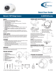
Quick Setup Guide VideoEdge IP Outdoor Mini-dome Part Number 8200-2646-07 B0 Quick Setup Guide WARNING At close range, infrared light can seriously damage a person's vision. Install this illuminator with a minimum safety zone of 1.22m ( 4 ft. ) between the illuminator and the closest possible human contact. Note: 1.22m ( 4 ft. ) is the actual measurement of the strength of the IR Illuminators that are being used. Note: CAMERA STARTS UP IN BLACK & WHITE BECAUSE THE IR ILLUMINATOR IS DISCONNECTED. For safety reasons, the IR Illuminator is disconnected at the factory. If the IR Illuminator were to accidentally trigger during install, it may pose a hazard to those within 4 feet. Once the camera is installed, reconnect the power lead (see manual). Ensure that you do not cover the photo cell (see manual) after power is reconnected as that may trigger the IR illuminator. SERVICE WARNING DO NOT LOOK DIRECTLY INTO AN OPERATONAL IR ILLUMINATOR. Since IR light is invisible to the human eye, the only method of verifying a malfunctioning IR illuminator is to observe the picture at the video output location. SAFETY PRECAUTIONS All the following safety and operational instructions to prevent harm or injury to the operator(s) or other persons should be read carefully before the unit is activated. WARNING To prevent fire or shock hazard, avoid exposing this unit to rain or moisture. Do not block ventilation openings. Do not place anything on top of the unit that might spill or fall into it. Do not attempt to service this unit yourself, as opening or removing covers may expose you to dangerous voltage or other hazards. Please refer all servicing to your distributor / retailer. Do not use liquid cleaners or aerosols for cleaning. To prevent fire or electric shock, do not overload wall outlets or extension cord. This unit must be grounded to reduce the risk of electric shocks. The installation should be made by a qualified service person. PoE considered a Network Environment 0 per IEC TR62101, and thus the interconnected ITE circuits may be considered SELV. CAUTION RISK OF EXPLOSION IF BATTERY IS REPLACED BY AN INCORRECT TYPE. DISPOSE OF USED BATTERIES ACCORDING TO THE INSTRUCTIONS. Copyright Under copyright laws, the contents of this manual may not be copied, photocopied, reproduced, translated or reduced to any electronic medium or machine-readable form, in whole or in part, without prior written consent of Tyco International Ltd. © Copyright 2009 and its Respective Companies. All Rights Reserved, American Dynamics 6600 Congress Avenue Boca Raton, FL 33487, U.S.A. 3 1. Name of parts and functions A. B. C. D. E. F. G. H. I. Inner plate mounting holes DC level Reset PC assembly IP module USB plug Side conduct entry Back conduct entry SD card slot 2. Adjusting the camera zoom and focus 1. 2. 3. 4. 5. 6. 4 Loosen the zoom ring thumbscrew. Turn the zoom ring to set the desired zoom. Tighten the zoom ring thumbscrew. Loosen the focus ring thumbscrew. Turn the focus ring to set the desired focus. Tighten the focus ring thumbscrew with the tool to adjust the focus. Quick Setup Guide Quick Setup Guide 3. Camera adjustment 1. Horizontal angle adjustment: turn the platform to adjust the horizontal angle B (90 degrees) and C (180 degrees). 2. Vertical angle adjustment: turn the platform to adjust the vertical angle A (90 degrees). 4. Mounting the housing 5 5. Install, configure and set the IP Dome Camera The CAMERA default setting is DHCP OFF. Users can build the CAMERA working environment with a static IP address. The default static IP is 192.168.1.168. You can set an IP address for the CAMERA if the LAN unit isn’t connected to a DHCP server. Or turn on to use the DHCP protocol if the DHCP server is working in the LAN, the CAMERA will obtain an IP address automatically from the DHCP server. The CAMERA is linked by its Video Out connection via a BNC connector to a monitor's Video In connection. If this connection is there, you can see some information on the monitor screen, such as the CAMERA factory default Static IP address. 1. Check the IP class of your PC Step 1: Select Settings from the Start menu, and then click Control Panel. Step 2: Double-click the Network Connections icon. The Network Connections dialog box appears. Step 3: Click the Protocols tab in the Network Connections dialog box. Step 4: Select Internet Protocol (TCP/IP) and click Properties. Step 5: Select Use the following IP Address to indicate that you do not wish to use DHCP, and assign IP Address 192.168.1.200 with Subnet mask 255.255.255.0. Click OK when you finish. Step 6: Choose Close to finish the modification. 2. Install UPnP Packets of your PC ® Microsoft Windows XP does not start the UPnP service by default. Some packets must be installed before it is initialized, as described below. Step 1: Select Set Program Access and Default from the Start menu. Step 2: Click the Add/Remove Windows Components button when the Add or Remove Programs dialog box appears. Step 3: Check the Network Services in the Windows Component Wizard dialog box, and then click Details. Step 4: Check UPnP User Interface, and choose OK. Step 5: Click Next when the original Network Component Wizard dialog box returns. After about one minute the UPnP installation is complete. Step 6: Select Finish to close. 3. Turn on Services of your PC After installation, turn on the relative services to start the UPnP protocol. The following procedures will demonstrate this. Step 1: Select Settings from the Start menu, and then click Control Panel. Step 2: Double-click the Administrative Tools icon. The Administrative Tools dialog box appears. Step 3: Click the Services icon in the Administrative Tools dialog box. Step 4: Double-click the SSDP Discovery Service icon when the Services dialog box shows up. Step 5: Choose Automatic in the Startup type, and click OK to start it. The Services dialog box appears again. Step 6: Double-click the Universal Plug and Play Device Host icon. Step 7: Choose Automatic in the Startup type, press the Start button, and click OK to start it. Step 8: Restart your system. 4. Set the static IP address in the IP Dome Camera. Step 1: Plug in the IP Dome camera’s power connection. Step 2: Plug the USB connector to your PC and the USB socket on the left flank panel. A window pops up asking if you want to "Run the program", "Open folder to view files", or " Take no action". Step 3: Choose "Run the program" and click "OK", and the "USB configuration " window will pop up. Step 4: Set the Network setting and type in the IP address you desire. Before you change the IP address, you should note the factory default Static IP address ( 192.168.1.168 ). Step 5: Click the "Apply" button in the "USB Configuration” window. A message pops up asking you to affirm the action as "OK". Step 6: Click "OK", and remove the USB connection from the window. Step 7: Click "Exit" at the bottom of the "USB Configuration” window to close the window. Or, choose the "Launch" button to see the local camera images directly. Before clicking "Launch", check your PC's IP address and use the Network connector ( RJ-45 ) to link up with your camera. Step 8: If you can see the images, then the IP setting is complete. 5. Scan IP Dome Camera through “My Network Place” After your installation and starting services, the UPnP protocol will take effect. Step 1: Scan all IP Dome Camera in My Network Place. Step 2: Double click the IP Dome Camera icon, and the video live stream will pop up automatically without assigning any IP address in Microsoft Internet Explorer. 6. Change the IP Dome Camera's control and operational settings. Step 1: Enter the IP address in the IE Browser. You will now see the IP Dome camera images. 6 Quick Setup Guide Quick Setup Guide Step 2: Use the buttons below the images to enter any other operational settings pages. Step 3: When you change any setting, please remember to click the "Submit” button in each page. NOTE: Enable DHCP Function: This function can only work if the LAN, which the unit is connected to, has a DHCP server. If the DHCP server is working, the IP Dome Camera will obtain an IP address automatically from the DHCP server. NOTE: The default "User Name" and "Password" are admin and 9999 respectively. If either the user name or the password is incorrect, please check the input data and rectify it as necessary. NOTE: When only one unit of the IP Dome Camera is connected to a computer or LAN, you can freely assign an IP address for the IP Dome Camera. For example, there is a range of IP Dome Camera IP addresses from 192.168.1.1 to 192.168.1.255. You can pick one for use from the range of the IP. It’s not necessary to set MASK and GATEWAY; leave the settings as default. When an IP Dome Camera is connected to a WAN, you must acquire a unique, permanent IP address and correctly configure the MASK and GATEWAY settings according to your network architecture. If you have any questions regarding those settings, please consult a qualified MIS professional or your ISP. Specifications Model Camera Image ADCIPE3712OCN ADCIPE3712OCPE ADCIPE3712OCPU ADCIPE3712OSN ADCIPE3712OSPE ADCIPE3712OSPU Image device Effective Pixels System CCD Setting IR wavelength / IR Length Min. Illumination Lens Compression Resolution Frame-rate Picture size (quality) Motion detection Interface Network Software Connectors Others Protocols Throughput Web browser Development tools Security Video output Alarm I/O/Reset SD card USB Reset Power requirement Power current consumption Operating Temperature Dimensions Approvals Accessories VideoEdge IP Outdoor Mini-dome, 3.7-12mm, clear, NTSC, w/PS VideoEdge IP Outdoor Mini-dome, 3.7-12mm, clear, PAL, EU Plug, w/PS VideoEdge IP Outdoor Mini-dome, 3.7-12mm, clear, PAL, UK Plug, w/PS VideoEdge IP Outdoor Mini-dome, 3.7-12mm, smoke, NTSC, w/PS VideoEdge IP Outdoor Mini-dome, 3.7-12mm, smoke, PAL, EU Plug, w/PS VideoEdge IP Outdoor Mini-dome, 3.7-12mm, smoke, PAL, UK Plug, w/PS 1/3” Sony Super-HAD CCD NTSC:768 x 494, PAL:752 x 582 NTSC/ PAL BLC, AGC, AWB, FL / Mirror / Shutter Speed 1/1000 700~1100nm (built-in 850nm) / 25m 0.5 Lux @F1.6, 0 Lux IR on 3.7~12mm Vari-focal auto iris DC drive lens MJPEG / MPEG4 D1/ 2CIF/ CIF 30 (25) / 24 / 15, 5 fps, adjustable MJPEG: 4~64KB MPEG4: 64Kbps ~ 8Mbps (Bit-rate) Motion Detection (96 zones, 5 levels) Ethernet (RJ-45 wired, 10/100 base-tx), MDIX support TCP/IP, DHCP, HTTP, ICMP, UPnP, ARP, DNS, DDNS, PPPoE, *FTP, *SMTP, RTP, RTSP 2.0M bytes/sec Microsoft IE 6.0 or above ActiveX / HTTP-API / SDK Multiple level / Multiple users / IP address filtering 1.0 Vpp, 75 ohm, composite, negative, BNC x 1 1/1/1 Alarm and Schedule recording / update Mini Type , 1.1 Slave for Configuration / Update Factory Default POE/802.3af class 3, DC 12V/750mA 700mA IR On, 500mA IR OFF 0°C ~ 50°C (32℉~ 122℉) 110mm(High) X 142 mm (Diagram) FCC, CE, RoHS User manual x 1 *Specifications are subject to change without notice. **FTP and SMTP functions for PAL version only. 7