1
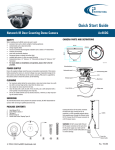
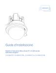
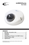
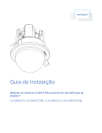
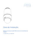
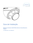
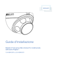
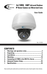
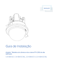
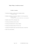
Quick Start Guide
Network 1MP Wedge Camera
Ax40W2/4/8-series
CAMERA PARTS AND DEFINITIONS
SAFETY
When installing your Ax40W camera be sure to avoid:
• excessive heat, such as direct sunlight or heating appliances
• contaminants such as dust and smoke
• strong magnetic fields
• sources of powerful electromagnetic radiation such as radios or TV transmitters
• moisture and humidity
• areas with mechanical vibrations
• fluorescent lamps or objects that reflect light
• unstable light sources as this may cause flickering
• temperatures below -10° Celsius or 14° Fahrenheit and above 40° Celsius or 104°
Fahrenheit.
• For more details on installation and operation, please refer to the CD
provided.
Equipment to be used in a Network Environment 0 per IEC TR62101. The camera is to
be connected only to PoE network that complies with IEEE 802.3af without routing to the
outside plant.
Camera Body - Top View
RESET
DEFAULT
Camera Dome
Camera Body - Side View
Ensure the supplied voltage meets the power consumption requirements of this camera
before powering the camera on. Incorrect voltage may cause irreparable damage to the
video camera and will effectively void the camera warranty. PoE power is supported by
this camera series.
CLEANING
•
•
•
DC12V
POE/ETHERNET
WARNING! DO NOT connect both PoE and
DC12V power connectors at the same time.
For DC power supply use, make sure the
polarity is correct to avoid malfunction and /
or camera damage.
For maximum optical clarity, the camera dome or lens must remain clean. Use a soft,
dry cloth to remove finger prints or dust from the dome cover.
Use a blower to remove dust from the lens.
Clean the body with a soft, dry cloth. If it is very dirty, use a cloth dampened with a
small quantity of neutral detergent, then wipe dry.
Do not use volatile solvents such as alcohol, benzene, or thinners, as they may damage the surface finishes.
DISASSEMBLING THE CAMERA
Before you mount and adjust the camera, follow these steps to disassemble the
camera.
SERVICING
To avoid electrical shock and to preserve the product warranty, DO NOT disasemble the
camera. Refer servicing to qualified personnel only.
PACKAGE CONTENTS
1. VIDEO OUT: Video output connector.
2. DEFAULT: Press and hold for 5 seconds
to return to factory default.
3. RESET: Press to reboot system.
Connect the PoE or DC12V power connector.
PoE (IEEE 802.3af): Connect the RJ-45 connector to a
PoE compatible network device that supplied power
through the Ethernet cable.
DC12V: Connect the DC12V power connector to a
DC12V power.
POWER SUPPLY
•
VIDEO OUT
1. Using the hex key provided,
loosen two screws on the cover.
2. Remove the dome cover.
0°
FRONT
1.
2.
3.
4.
5.
6.
7.
8.
9.
10.
11.
User Manual CD x1
Guide Pattern sticker x1
2nd video monitor output BNC cable x1
Hex key x1
Plastic Anchor x2
Round Head Screw (Tapping Type) x2
Flat Head Screw (Machine Type 30L) x2
Wing (Butterfly) nut x2
Washer x2
Standard RJ45 Connector x2
Desiccant in a package x1
270°
User Guide
IP Finder
90°
1. Take the desiccant out of the package (#11 on the Accessories list)
2. Peel the protective layer revealing the adhesive surface on the desiccant and
attach to the inside of the dome cover as shown in the diagram below.
CABLE
180°
1
ATTACHING THE DESICCANT
2
Attach
dessicant to
the inside
of the dome
cover
3
4
5
6
7
8
9
i3-TRNG-CAMS-Ax40W-series-QuickGuide.indd
10
11
Peel the
protective
layer on the
desiccant
Rev. 141126
QUICK START GUIDE
Ax40W-series Network Wedge Camera
MOUNTING THE CAMERA (SURFACE MOUNT)
CONNECT CAMERA TO i3 SRX-PRO SERVER
Depending on mounting surface, you can use a combination of Plastic Anchors and
Tapping Screws or Machine Type Screws, Wing nuts and Washers.
Connection Type 1:
Crossover direct connection
1. Prepare the mounting surface. Adhere the Mounting Template (#2 on Accessories
list) to the surface.
2. Drill two screw holes on the mounting surface as well as one round hole Ø30mm in
diameter, according to the template.
3. If installing on solid surface, insert the Plastic Anchors (#6 on Accessories list) into
two holes.
4. Pass all the signal cables through the Ø30mm hole.
5. If installing on solid surface, secure the camera body to the mounting surface with
the Tapping Type Screws (#5 on Accessories list).
If installing on a T-bar ceiling, secure the camera body to the mounting surface
with the Machine Type Screws (#7 on Accessories list) below the mounting surface
and Wing Nut/Washer combo above the mounting surface (#8 & #9 on Accessories
list).
i3 SRX-Pro Server
Connection Type 2:
LAN
i3 SRX-Pro Server
4
3
SOLID SURFACE MOUNTING
T-BAR MOUNTING
0°
0°
FRONT
FRONT
1
1
270°
90°
270°
90°
Ø 30mm
Ø 30mm
CABLE
CABLE
2
180°
180°
2
3
ADJUSTING THE CAMERA / COMPLETING INSTALLATION
1.
2.
3.
4.
5.
Loosen two screws, as shown in the picture below.
Adjust the lens to the desired shooting angle until the required view is achieved
Re-tighten the screws once the desired view is achieved.
Re-attach the dome cover carefully
Re-tighten two screws that hold the camera dome cover. This completes the
installation.
Loosen two screws
before adjusting the lens
i3 INTERNATIONAL INC.
Via Gigabit Switch
1.866.840.0004
www.i3international.com
Camera’s default IP: 192.0.0.16.
Default Login/Password:
FW ver. i3_00_026-40 | Login: admin / Password: 1234
FW ver. i3_00_39-51, or higher | Login: i3admin / PW: i3admin
1. Close SRX-Pro Server software by pressing Alt+Shift+Ctrl+F4.
2. Change the IP address on the onboard NIC (LAN) (or on NIC1 if your SRX-Pro
Server has two onboard NIC cards) of your SRX-Pro Server to 192.0.0.XXX to
match the default IP range of your Annexxus IP camera.
3. Connect your camera to i3 SRX-Pro Server (see diagram above).
4. Turn on your Annexxus camera.
5. Launch the CD that came with your Annexxus camera and double-click
“AnnexxusFinder.exe” file to install Annexxus Finder application. Annexxus
Finder application discovers all Annexxus cameras connected to your network.
6. Select desired camera in the Annexxus Finder software by double-clicking it in
the list and click Edit.
7. Enter the new IP address and Subnet Mask of the camera in the Change IP
Address area. The new camera IP address must match the original range of your
SRX-Pro LAN or NIC1 card.
E.g. If your original SRX-Pro Server’s IP address was 192.138.10.122, change
your Annexxus camera’s IP address to 192.138.10.XXX.
8. Follow the Annexxus Finder installation instructions until the application has been
successfully installed on your SRX-Pro Server.
9. Double-click Annexxus Finder icon on the Desktop to launch the application.
The application window will appear displaying a list of active network cameras.
Remember: Annexxus Cameras cannot share an IP address, each camera
requires its own unique IP address.
10. Enter the default camera password in the Input Password field and click Save.
11. Wait a few moments for a successful confirmation window. Click OK to close it.
12. Repeat Steps 1-12 for all detected Annexxus cameras in the Annexxus Finder.
13. Make sure you can connect to the camera through Internet Explorer:
a. Launch Internet Explorer and enter the IP Address you have just assigned to
your Annexxus camera. The password window should be displayed.
b. Enter the default camera User Name and the default Password.
c. Annexxus camera interface will be displayed in the Internet Explorer
window. You should be able to see the camera image on the screen.
If you do not see the camera image on the screen, call i3 International tech
support for troubleshooting tips: 1.877.877.7241
14. Make sure that the latest version of GiPi updater is installed on your SRX-Pro
Server. You can download the updates from ftp://files.123ip.com/drivers/gipi.
Please contact i3 Technical Support team for access information.
15. Once the latest GiPi updater has been installed, restart i3 SRX-Pro Server
software.
16. Log In and go to the Setup -> IP Camera tab.
17. Click the Search button to display connected Annexxus cameras.
18. Select the detected camera in the list and click Select.
19. In the Select IP Camera window, enter the default camera User Name and the
default Password, then click Add.
20. The selected camera will be added to the IP Camera list.
Don’t forget to assign the IP camera to the SRX-Pro video channel in the
corresponding column.
21. Your Annexxus camera is now connected to SRX-Pro Server and is ready to
record. You may change resolution and frame rate for the Annexxus camera in
the IP Camera tab menu or you may choose to configure the camera’s advanced
settings.
U.S.A 1967 Wehrle Drive, Suite 1,
PMB# 034 Buffalo NY, 14221
Canada 780 Birchmount Road, Unit 16,
Scarborough, ON, M1K 5H4