1
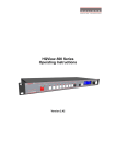
LEDView Setup Guide
Version 2.4
Calibre UK Ltd
Cornwall House,
Cornwall Terrace
Bradford, West Yorkshire
BD8 7JS, England
Telephone +44 (0)1274 394125
Fax + 44 (0)1274 730960
Email [email protected]
Web-site www.calibreuk.com
Contents
Introduction
The Basic System
Flexible Connectivity
Control via Web Browser
Set Scaler Functions
Check loaded firmware is set to LED
Set Processor Output Resolution
Set Output Frame Rate
Set Display Window Size
Set Picture Format
Additional output Settings
Output Config
Input Characteristics
Input Adjustments
Back up settings and personal Test Patterns
©Calibre UK Limited issue 2.4 November 2012
2
3
4
5
7
7
7
7
8
9
10
11
11
12
15
Page 1
Introduction
This guide is a non-technical introduction to scaling for an LED wall using the Calibre UK range of
LEDView scalers/processors as featured below.
The guide describes how to setup, scale and fit the image quickly and simply onto the LED wall, how
to adjust for the best pictures and how to back-up your settings to a PC.
This guide does not replace the product user manual and covers only the essential functions to get
started
LEDView400
LEDView510
LEDView530
©Calibre UK Limited issue 2.4 November 2012
Page 2
The Basic Setup
Calibre LEDView processors are single channel devices so you need to use one processor for each
LED wall you have. The LEDView is a high quality image scaler and does not replace your existing
LED wall controller/matrix but designed to work with it.
The flowchart below represents the basic setup, additional information can be found further in this
guide.
Setting up LEDView scaler/processors for single LED Wall
Connect Inputs and DVI output to Controller
Boot Scaler and Set Output resolution (Menu/Output)
Set Scaler output Frame rate (Menu/Output/Frame Rate)
Set display window size (Menu/Output/Output Window size)
Set picture format (Menu/Geometry/Picture Format)
Set input characteristics (Menu/Enhancement/)
Video Filters
Input Adjustments
Backup Settings to PC
©Calibre UK Limited issue 2.4 November 2012
Page 3
Flexible Connectivity
The LEDView range can be used as a routing switcher and universal interface for connecting LED
screens to;
HD-SDI, 3G-SDI*, HDMI, DVI, VGA Analog, Component YPbPr, RGsB/RGBS, Composite & S-Video
inputs with signal compatibility up to 1080p & WUXGA
The DVI input can also be set to Analogue input so 2 x VGA can be connected if needed
Available outputs are HDMI/DVI, 3G-SDI* & VGA Analog.
*LEDView510 and LEDView530 only.
LEDView400
LEDView510/LEDView530
©Calibre UK Limited issue 2.4 November 2012
Page 4
Control Via Web Browser
All LEDView can be controlled with either on screen display (OSD) menu or use the built in web
browser on a Laptop or Wi-fi enabled Smartphone.
LEDView530 only has front panel LCD menu panel
The menu format is the same in all menu methods.
Units will be set to DHCP as default.
You can use the discovery tool to connect to any Calibre processors found on your network. You can
download this software from our website.
http://www.calibreuk.com/software/ledview/DiscoveryTool_V1.0.exe
Or
Use a static address
Factory default address will be IP 169.254.000.001 Mask 255.255.000.000 you can use this or
manually set an address of your choice to match
You can find the network settings in menu/system/network settings
©Calibre UK Limited issue 2.4 November 2012
Page 5
If you choose to use a static address please turn DHCP to OFF and then cycle the power on the
processor.
This is the top menu screen when you successfully opened the internal browser menu
The menu structure is the same with very few exceptions
Where the structure is the same reference has been made throughout the document to the LCD
menu
Where the menu structure differs for the upload of patterns and the settings file back-up and
restore functions reference is made to the browser menu.
©Calibre UK Limited issue 2.4 November 2012
Page 6
Set Scaler Functions
Set the ‘menu time out function’ to ‘infinite’ (time out function is disabled) to give more time to
operate the processors and read these notes.
This can be done from the top menu select ‘System’ then select ‘Menu Settings’ then select ‘Menu
Display Time’ and then select ‘Infinite’.
Input on the latest firmware defaults to the ASPECT test pattern. If your unit has been set to
something else Set the ‘input’ to ‘test pattern’
Check loaded firmware is set to LED
Menu/Output/Display Type/Display
Set ‘output/display type’ to LED
Set Processor Output Resolution
Set the processor output resolution to a resolution equal or greater than the native resolution of
your display.
Menu/Output/Display Type/Output Mode
Note that on some ‘low cost’ displays the controller cannot successfully display some resolutions. If
interference to the displayed image is noticed, try using a higher output resolution and reset the
Display Window size
Please also note that the symbol of a BNC connector with a red cross denotes resolutions that are
not part of the “SDI Standard” and these resolutions will not appear on the SDI output.
Set Output Frame Rate
This allows the processor to be set to give either 50HZ or 60Hz vertical refresh. This is particularly
important for installations where live cameras will be shown in shot. Also note that movement in
recorded playback material may look smoother if played out at its native refresh rate.
Menu/Output/Frame Rate
Please note that some LED walls will not work at 50HZ
The default frame on all LEDView is set at Auto
©Calibre UK Limited issue 2.4 November 2012
Page 7
Set Display Window Size
This section allows the quick and convenient setting of the area of interest to fit the LED screen with
pixel-accurate output scaling to accurately match the actual size of the screen you are using.
Menu/Output/Output Window Size
In the Output menu select Output Window Size
Set window Size Enable to ON
Set the four edges of the picture to fit the edges of your screen
In the browser menu actual numbers can be entered
Please note that the browser menu allows actual numbers of pixels to be entered – please click
outside the box to register the entered number.
©Calibre UK Limited issue 2.4 November 2012
Page 8
Set Picture Format
Picture Format allows a user to select the displayed aspect ratio where the signal input is different to
the display’s natural aspect ratio.
Choose between Standard, Full Screen, Crop, Anamorphic or Theatrescope
Select the input channel that has your picture. There is a choice of display modes as described below
Menu/Geometry/Picture Format
In main menu Geometry select Picture Format
Choose between Standard, Full Screen, Crop, Anamorphic or Theatrescope
a/ Standard preserves the size and aspect ratio of the incoming image. Areas of the display that
are un-used are displayed black (letterboxed).
b/ Full Screen scales the image to the size of the display without preservation of the aspect ratio.
Please note that some signals have black borders which will be displayed as black.
©Calibre UK Limited issue 2.4 November 2012
Page 9
c/ Crop preserves the aspect ratio of the image and scales the image to fill the screen.
The smaller axis of the image will fill the space available. The result is that either the top/bottom or
right/left areas of the image are cropped.
d/ Anamorphic scales the input image to display the whole picture in a 16:9 aspect ratio.
Areas of the display that are un-used are displayed black
e/ Theatrescope scales the input image to display the whole picture only for use with a projector
which has a special anamorphic lens that optically stretches the 16:9 back to 2.35:1 at the screen.
The integer scaling fraction is 1080/817.
Please note that some signals have some black pixels added to make up the pixel count to conform
to a particular standard e.g. 702 pixels horizontal are normally made up to 720 by adding 18 black
pixels (should be 9 either side, but not always). These pictures will be shown with the black
boarders. Such inputs require the use of the zoom and pan/tilt functions to display full screen.
Additional Output Settings
The Output Menu provides comprehensive separate adjustments for the output of the processor to
match the display.
Please note that in the Calibre processors this quite separate to the adjustments provided for each
input channel, internal test patterns should be used to adjust the output.
Colour Balance
Menu/Output/Gamma Color Crush/Native Colour Temp
This allows the processor to be set to give the best colour suitable for your LED wall application.
Please use the internal test patterns when setting these characteristics
(Using an input signal could lead to confusion)
There are a selection of preset colour balance selections for your convenience
Gamma
Menu/Output/Gamma Color Crush/Output Gamma
In this section you can choose the Output Gamma to match the specification of your LED wall.
Black Crush
Menu/Output/Gamma Color Crush/Gamma Colour Crush
The LED firmware features a black crush feature. This is for suppressing sparkles on the LED wall
caused by noise in the signal.
Note: This is quite separate from the Brightness function.
©Calibre UK Limited issue 2.4 November 2012
Page 10
Output Config
Output configuration contains a range of options to tailor the output characteristics which default to
the most commonly found requirements. Please refer to the user manual if you wish to modify these
settings
Menu/Output/Output Config/
Set Input Characteristics
Input Filters
Each input of the Calibre processor has a dedicated memory. This allows the input characteristics to
be set for each channel without affecting the output calibration.
Our menu system is contextual therefore some filters will be greyed out if they are not applicable to
that input
In the main menu select Enhancement
The LTI filter enhances the sharpness of the luminance (B&W) signal.
The CTI filter enhances the colour signal by increasing the steepness of colour edges.
TRNR (Temporal Recursive Noise Reduction) and MNR (Mosquito Noise Reduction) are
available for SD input signals only. These filters reduce spatial and temporal noise as well as
block artifacts.
CCS is a filter to reduce luminance to chrominance cross talk of composite video signals
(only) which appears as a coarse rainbow pattern or random colours in regions of fine
details.
©Calibre UK Limited issue 2.4 November 2012
Page 11
Input Adjustments
Calibre processors provide comprehensive separate adjustments for each input channel. The active
adjustments are for which ever input is currently selected.
Colour
From the main menu select Colour
Black level offset is ‘0’ for European tv signals and ‘7.5’ for NTSC or USA originated signals
Black Level is like the brightness control on a domestic tv
Contrast is the intescity of the white level gain
Saturation is the intensity of the colour
Hue is the colour correction available for NTSC originated signals. It is available to PAL type signals in
case the transfer from the NTSC signal was done with a poor hue balance
RGB Values
A full Process amplifier is available for setting the individual gain and black level of each of the RGB
values that make up the colour balance of the selected input
Colour Balance gives a choice of preset colour balances
Input Gamma gives a selection preset gamma curves to allow you to match with your input signal
Addition Input Adjustments
Input Config
Menu/System/Input Config
VGA Set-up is available when the VGA input is selected and allows manual override to the timing of
this input
DVI/HDMI Setup provides a range of choices for these two input ports. Please refer to the user
manual for a full explanation of each function. However there are two items that are important to
mention here
DVI-I Port This port defaults to a digital input port. It can be switched to be an analogue port
therefore allowing it to act as a second VGA input
HDCP Input function is to allow the HDCP compliance to be turned off. This is for use with
MAC computers if the whole of your system is not HDCP compliant. By making our processor
appear non-compliant the MAC does not encrypt its output allowing material to be shown in
non-compliant systems
System/Input Config/DVI HDMI Setup/HDCP Input
©Calibre UK Limited issue 2.4 November 2012
Page 12
SDI Setup allows the SDI stream standard to be set and the audio channel routing to be set.
Component Setup allows the analogue BNC inputs to be configured for YUV or RGsB/RGBS
Test Pattern Setup which allows you to pre-select which pattern you wish to display when Test
Pattern is selected in the Input list.
This is often used to display an end user uploaded test pattern which can be your company logo.
Switching Transition you can select how the unit switches between inputs. Please select from a
freeze of the last input to be switched when the timing of the next input has been accommodated,
or choose a fade via black.
Pan/Tilt/Zoom
Additional positional adjustments can be made using PAN/Tilt/Zoom. Please note that using this
function incurs a penalty of additional latency. One additional progressive frame is added to the
processing time.
©Calibre UK Limited issue 2.4 November 2012
Page 13
Back-up your settings and Upload your own Test Patterns
These functions can only be accessed through the browser menu. They are additional items that
cannot be found on either the LCD or ON Screen menus.
You can upload four patterns/logo pictures of your choice.
You can also backup your settings to your laptop. You can use this function to load multiple units
with an experts settings.
E&OE
©Calibre UK Limited issue 2.4 November 2012
Page 14