1
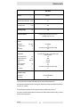
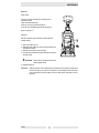
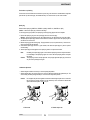
0203080en
002
04.2008
Vibratory plate
BPU 3050A
Operator´s Manual
CONTENTS
Type
Item no.
BPU 3050A
0008763 ...
This machine has been equipped with an EPA certified engine.
Additional information can be found in the engine manufacturers notes.
WARNING
The engine exhaust from this product
contains chemicals known to the State
of California to cause cancer, birth
defects or other reproductive harm.
Caution
This engine is an EPA engine.
Adjusting the engine speed will interfere
with EPA certivication and emissions.
Only authorized personnel can make
adjustments to this engine.
Please contact you nearest engine or
Wacker Dealer for more information.
H00611GB
1
2
FOREWORD
Foreword
For your own safety and protection from bodily injuries, carefully read, understand and follow the safety instructions in this manual.
Please operate and maintain your Wacker machine in accordance with the instructions in this manual.
Defective machine parts are to be replaced as soon as possible.
All rights, especially the right for copying and distribution are reserved.
Copyright by Wacker Construction Equipment AG.
No part of this publication may be reproduced in any form or by any means, electronic or mechanical, including
photocopying, without express permission in writing from Wacker Construction Equipment AG.
Any type of reproduction, distribution or saving on data carriers of any type or method not authorized by Wacker
represents an infringement of valid copyrights and will be prosecuted.
We expressly reserve the right to technical modifications- even without express due notice - which aim at improving our machines or their safety standards.
T00778GB
3
TABLE OF CONTENTS
FOREWORD
3
SAFETY INSTRUCTIONS
6
General instructions
Operation
Safety checks
Maintenance
Transport
Maintenance checks
6
6
7
7
7
7
TECHNICAL DATA
8
DESCRIPTION
9
Applications
Dimensions
Max. admissible inclination
Description of function
9
9
9
10
TRANSPORT TO WORK SITE, RECOMMENDATIONS ON COMPACTION
Transport to work site
Recommendations on compaction
11
11
11
OPERATION
12
Engine check before starting
Starting the engine
Operation the engine
Forward and reverse motion
Stopping the engine
12
12
14
14
15
MAINTENANCE
16
Maintenance schedule
Engine oil
Hydraulic control
Exciter
Exciter V-belt
Fuel strainer cup cleaning
Spark plug
Carburettor adjustment
Air filter service
16
17
18
18
18
19
19
19
20
4
TABLE OF CONTENTS
FAULTS
21
Reverse speed too low
Forward speed too low
No advance
Loss of hydraulic oil
Engine does not start
21
21
21
21
21
EC - CONFORMITY-CERTIFICATE
23
5
SAFETY INSTRUCTIONS
SAFETY INSTRUCTIONS FOR THE USE OF VIBRATORY
PLATES WITH COMBUSTION ENGINES
General instructions
1.
Vibratory plates may only be operated by persons who
*
*
*
*
are at least 18 years of age
are physically and mentally fit for this job
have been instructed in guiding vibratory plates and proved their ability for the job to the
employer
may be expected to carry out the job they are charged with carefully.
The persons must be assigned the job of guiding vibratory plates by the employer.
2.
Vibratory plates may only be used for compaction jobs. Both the manufacturer’s operating instructions
and these safety instructions have to be observed.
3.
The persons charged with the operation of vibratory plates have to be made familiar with the necessary
safety measures relating to the machine. In case of extraordinary uses the employer shall give the
necessary additional instructions.
4.
It is possible that this vibratory plate exceeds the admissible sound level of 89 dB (A). According to the
rules for the prevention of accidents regarding emission of noise, the employees have to wear ear protection if the sound level reaches 89 dB (A) or more.
Operation
1.
The engine is started by way of a recoil starter. The automatic decompression system makes possible
a simple and backstroke-safe engine starting procedure.
2.
The functioning of operating levers or elements is not to be influenced or rendered ineffective.
3.
During operation the operator may not leave the control elements.
4.
The operator has to stop the engine of the vibratory plate before going on breaks. The machine has to
be placed such that it cannot turn over.
5.
Stop engine before filling fuel tank. When refilling fuel tank, do not allow fuel to come into contact with
the hot parts of the engine or spill onto the ground.
6.
Do not smoke or handle open fire near this machine.
7.
The tank lid must fit tightly. Shut off fuel cock, if available when stopping the engine. For long distance
transports of machine operated by fuel or fuel - mixtures, the fuel tank has to be drained completely.
☛ATTENTION! Leaky fuel tanks may cause explosions and must therefore be replaced immediately.
8.
Do not operate the machine in areas where explosions may occur.
9.
Make sure that sufficient fresh air is available when operating vibratory plates with combustion engines
in enclosed areas, tunnels, adits and deep trenches.
10.
During operation keep your hands, feet and clothes away from the moving parts of the vibraton plate.
Wear safety shoes, and eye protection glasses in case of trench operation where falling sand stones
maybe ejected.
11.
When working near the edges of breaks, pits, slopes, trenches and platforms, vibratory plates are to be
operated such that there is no danger of their turning over or dropping in.
SV00019GB
6
SAFETY INSTRUCTIONS
12.
13.
14.
15.
16.
17.
Make sure the soil or subsoil to be compacted has a high enough load carrying capacity.
Use appropriate protective clothing while working or while carrying out maintenance work.
When traveling backwards the operator has to guide the vibration plate laterally by its guide handle so
that he will not be squeezed between the handle and a possible obstacle. Special care is required when work
ing on uneven ground or when compacting coarse material. Make sure of a firm stand when operating
the machine under such conditons.
Vibratory plates are to be guided such that hand injuries caused by solid objects are avoided.
Vibratory plates have to be guided such that their stability is guaranteed.
Machines with integrated transport trolley may not be parked or stored on the trolley. This device has
only been designed to transport the machine.
Safety checks
1.
2.
3.
4.
5.
Vibratory plates may only be operated with all safety devices installed.
Before starting operation, the operator has to check that all control and safety devices function properly.
Immediately notify your supervisor or superintendent if you have determined defects in the safety devices or other defects which could endanger the safe operation of the machine or which could endanger
the environment.
In case of defects jeopardizing the operational safety of the vibration plate, the machine has to be
stopped immediately.
Process materials and operating fuels must be stowed away in receptacles or containers marked according to the respective manufacturers specifications.
Maintenance
1.
2.
3.
4.
5.
6.
Only use original spare parts. Modifications to this machine, including the adjustment of the maximum
engine speed set by the manufacturer, are subject to the express approval of Wacker. In case of nonobservance all liabilities shall be refused.
All drive units have to be switched off before carrying out maintenance jobs. Deviations from this are only
allowed if the maintenance or jobs require a running engine.
When working on vibratory plates equipped with electric starter, disconnect battery before carrying out
maintenance or repair jobs on the electric parts of the machine.
Remove pressure from hydraulic lines before working on them. Caution: take care when removing hydraulic lines, for the oil may be very hot (up. over 80o C). Precautions are to be taken to prevent oil from
splashing into the operator’s eyes.
As soon as maintenance and repair jobs have been completed all safety devices have to be reinstalled
properly.
Do not hose down the machine with water after each use to avoid possible malfunctions. Do not use high
pressure washers nor chemical products.
Transport
1.
2.
3.
During transport, loading and unloading of vibration plates by means of lifting devices, appropriate slinging means or hooks have to be used on the lifting points provided for this purpose on the vibratory plate.
The load-carrying capacity of the loading ramps has to be sufficient and the ramps have to be secure
such that they cannot turn over. Make sure that no one be endangered by machines turning over by slipping or by moving machine parts.
When being transported on vehicles, precautions have to be taken that vibration plates do not slip or turn
over.
Maintenance checks
According to the conditions and frequency of use, vibratory plates have to be checked for safe operation at
least once a year by skilled technicians, such as those found at Wacker-service depots and have to be repaired
if necessary.
Please also observe the corresponding rules and regulations valid in your country.
SV00019GB
7
TECHNICAL DATA
BPU 3050A
Item no.
0008763 ...
Advance and reverse travel
Compacted area
Operating weight
m/min:
21
m2/h:
630
kg:
166
Power transmission
From drive engine directly to exciter unit via
centrifugal clutch and V-belt
Exciter
Vibrations
Centrifugal force
Oil
Oil quantity
min-1 (Hz):
kN:
l:
Drive motor
Piston displacement
Engine speed (rpm)
Rated power (*)
Fuel
Fuel consumption
Tank capacity
Oil
Oil quantity
ca. 5400 (90)
30
Fuchs Titan Unic 10W40 MC (SAE 10W40)
0,6
l:
Air-cooled single-cylinder 4-cycle gasoline engine
with recoil starter
270
2800
5,2 (6,9)
Gasoline
1,1
5,0
Fuchs Titan Unic 10W40 MC (SAE 10W40)
1,1
l:
Fuchs Renolin MR 520
0,4
cm3:
min-1:
kW (PS):
l/h:
l:
Hydraulic control
Hydraulic oil
Oil quantity
(*) In accordance with the installed useful outlet power according to Directive 2000/14/EG.
The sound pressure level at the operator‘s working place, determined according to the EN ISO 11204 standard,
is equal to LpA = 93 dB(A).
The weighted effective acceleration value, determined according to EN ISO 5349 is 2,8 m/s2.
The sound and vibration measurements were carried out and obtained with the machine working on crushed
gravel at nominal engine speed.
TD00611GB
8
DESCRIPTION
Applications
The machine is perfectly suited for the compaction of all types of soil including semi-cohesive soils in trench
and surface compaction applications as well as for the compaction of asphalt pavements and the vibration of
interlocking paving stones. This machine is the most universally deployable machine of this line of products
thanks to the optimum balance between the centrifugal force and the contact surface.
Dimensions
Max. admissible inclination
T00855GB
9
DESCRIPTION
Description of function
The vibration required for compaction is produced by the exciter (5) which is firmly joinded to the lower mass
(4). This exciter (5) is designed as a central vibrator with aligned vibrations. Such a principle permits the direction of vibration to be changed by turning the eccentric weights (13). In this way an infinitely variable transition
between vibration in forward motion, at standstill and in reverse motion is possible.
This process is hydraulically controlled with the operating control handle (7) on the centre pole head (8).
Forwards
On the spot
Reverse
The drive engine (1) is anchored to the upper mass (3) and drives the exciter (5). The torque is transmitted by
means of a friction connection through the centrifugal clutch (9) and the exciter V-belt (10).
The centrifugal clutch (9) interrupts the power transmission to the exciter (5) at low engine turning speed, thus
allowing for a perfect idling speed of the drive engine (1). The turning speed of the engine (1) can be infinitely
adjusted by way of the throttle lever (6).
The upper (3) and lower (4) masses are connected to each other by 4 vibration-damping shock mounts (11).
This damping system prevents the very high frequencies from being transmitted to the upper mass (3). As a
result the functionability of the drive engine (1) is retained in spite of the high compaction performance.
he drive engine (1) works according to the 4-stroke principle, is started by way of a recoil starter, sucks in combustion air over a dry air filter (12) and is air-cooled.
To facilitate the starting procedure the drive engine (1) has an decompression mechanism.
T00855GB
10
TRANSPORT TO WORK SITE, RECOMMENDATIONS ON COMPACTION
Transport to work site
Conditions:
- To transport the vibration plate, use only suitable lifting equipment with a minimum load-bearing capacity
of 200 kg.
- Only attach suitable tackle at the central lifting point (15) provided.
- Always tie down the vibratory plate by the protective frame (14) and latch the center pole in place during
transport of the vibratory plate on the loading area of a transport vehicle.
☛ATTENTION!
Note:
The engine must be stopped when using the integrated transport device
Lubrication of the engine is not guaranteed if the engine is running when the plate is in
transport position.
This could lead to serious engine damages.
Furthermore the danger exists that oil will spill out of the crankcase breather.
Also observe the regulations in the chapter “Safety instructions“.
Recommendations on compaction
Ground conditions
The max. compaction depth depends on several factors relating to the ground condition, such as moisture,
grain distribution etc.
It is therefore not possible to specify exact values.
Recommendation: In each case determine the max. compaction depth with compaction tests and soil samples.
Compaction on slopes
The following points are to be observed when compacting on sloped surfaces (slopes, embankments):
*
*
*
Only approach gradients from the bottom (a gradient which can be easily overcome upwards, can also be
compacted downwards without any risk).
The operator must never stand in the direction of descent (see chapter “Safety instructions“).
The max. gradient of 20o must not be exceeded.
☛ATTENTION!
If this gradient were exceeded, this would result in a failure of the engine lubrication system (splash lubrication) and thus inevitably lead to a breakdown of important engine
components.
Wrong !
T00856GB
Right !
11
OPERATION
Engine check before starting
1. Oil level check
Insert dipstick in oil filler neck, but without screwing in. If oil level is low, fill to the top of the oil filler neck with
high grade Fuchs Titan Unic 10W40 MC oil.
☛ATTENTION!
Place machine in horizontal position before checking engine oil level.
2. Dual-air cleander >Dual element type<
Check the air cleaner elements to be sure they are clean and in good condition. Clean or replace the elements if necessary.
3. Fuel
Use any regular grade automotive gasoline (unleaded gasoline is preferred) with a pump octane rating of
86 or higher.
Never use an oil/gasoline mixture or dirty gasoline: Avoid getting dirt, dust or water in the fuel tank.
Caution:
Gasoline substitutes are not recommended, they may be harmful to the fuel system components.
Starting the engine
1. Move the fuel shut-off valve (lever in arrow direction) to the „ON“ position.
2. Move the choke lever to the CLOSE position.
Note: If the engine is warm or the air temperature is high, move the control lever away from the CHOKE
postion as soon as the engine starts.
T00857GB
12
OPERATION
3. Pull the throttle lever (6) back slightly.
4. Turn the engine switch to the „I“ position.
5. Pull the starter grip lightly until resistance is felt, then pull briskly.
Caution:
T00857GB
Do not allow the starter grip to snap back against the engine. Return it gently to prevent
damage to the starter.
13
OPERATION
Operation the engine
As the engine warms up, gradually move the choke lever to the OPEN position.
Position the throttle lever for the desired engine speed.
Oil alert system
The oil alert system is designed to prevent engine damage caused by an insufficient amount of oil in the crankcase. Before the oil level in the crankcase drops below a safe limit, the oil alert system will automatically shut
down the engine (the engine switch will remain in the „I“ position).
Note: If engine does not start check oil level
Forward and reverse motion
The engine speed can be infinitely varied with the throttle control lever (6).
The direction of travel is determined with the operating control handle (7).
Depending on the position of the control handle (7), the vibration plate compacts in forward direction, on the
spot or in reverse direction.
Forwards
T00857GB
On the spot
14
Reverse
OPERATION
Stopping the engine
To stop the engine in an emergency, turn the engine switch to the „0“ position.
Under normal conditions, use the following procedure:
1. Push the throttle lever forward all the way to the stop.
2. Turn the ignition switch to the „0“ position.
3. Turn off the fuel shut-off valve (lever in arrow direction).
T00857GB
15
MAINTENANCE
Maintenance schedule
Parts
Maintenance jobs
Maintenance interval
Air filter
daily
Fuel tank
Engine oil
Exciter
Bowden cable
Check for external damage and tight fit.
Check filter cartridge, clean or replace if necessary.
Check tank lid for tight fit, replace if necessary.
Check oil level, top up if necessary.
Check for tightness.
Check to see smooth running.
Engine oil
First oil change.
after 20 hours
Ignition system
Exciter
Hydraulic control
V-belt
Protective frame
Clean spark plug, check spark plug gap 0,7 mm.
Check attachment screws for tight fit.
Check oil level, top up if necessary.
Check V-belt tension-retension, if need be.
Check fastening screws of protective frame and
central suspension for tight fit.
monthly
Engine oil
Exhaust muffler
Further oil changes.
Remove combustion residue from spark arrester.
after 100 hours
Exciter
Check oil level-fill up, if need be.
after 150 hours
Exciter
Oil change.
after 250 hours
Valve clearance
Check, set - 0,15 mm intake valve, 0,20 mm exhaust
valve.
after 300 hours
T00858GB
16
MAINTENANCE
Engine oil
Check oil level:
The engine must be horizontally place when filling in oil or
checking the oil level.
Check oil level with dip stick (16).
If oil level is to low, top up with brand quality oil
Fuchs Titan Unic 10W40 MC through oil feed opening (16).
Engine oil capacity: 1,1 l.
Oil change:
Drain the oil while the engine is still warm to assure rapid and
complete draining.
1. Remove the oil filler cap (16).
2. Release the waist oil drain hose (2) and collect the draining oil in
an appropriate container.
3. Attach the waist oil drain hose (2) back again.
4. Pour the recommended oil through the oil filler tube (16) and then
check the oil level.
☛ATTENTION!
Place machine in horizontal position before
checking engine oil level.
5. Install the oil filter cap.
Take notice:
T00858GB
Please pay attention to the corresponding environmental laws when disposing of used engine
oil. We recommend you carry the oil in a container to a central collecting point for used oils. Do
not pour used engine oil into the garbage nor into the sewer system, waste pipes or even on
the ground.
17
MAINTENANCE
Hydraulic control
Check oil level:
1. Move centre pole into vertical position.
2. Push operating control handle (7) to forward
travel position.
3. Open filler bore (17).
4. The oil level must reach the upper edge
Oil
of the gear; add Fuchs Renolin MR 520
hydraulic fluid if required.
5. Close filler bore (17).
Hydraulic control system is self-bleeding.
Exciter
Check oil level:
1. Position vibration plate horizontally.
2. Open filler bore (19).
3. The oil level must reach the start of the thread (19) of
the filler bore.
4. If necessary, pour in brand oil Fuchs Titan Unic 10W40
MC through filler bore (use funnel).
5. Close filler bore (19).
Changing the oil:
1. Open filler bore (19).
2. Tilt vibration plate and keep it tilted until the oil has run
out.
3. Place vibration plate in horizontal position.
4. Pour in 0,6 l brand oil Fuchs Titan Unic 10W40 MC
through the filler bore (19).
5. Close filler bore (19).
☛ATTENTION! Do not pour in too much oil!
Exciter V-belt
Remove belt guard. Remove the screws from the engine’s V-belt pulley and then pull off the V-belt pulley half.
Take out the necessary number of discs (removal of one disc is usually enough). Place the discs just removed
on the outside of the V-belt pulley half. Turn in the screws by hand and then alternately tighten while constantly
turning the engine’s V-belt pulley. Run the machine a few moments and then retighten the screws if necessary.
T00858GB
18
MAINTENANCE
Fuel strainer cup cleaning
Turn the fuel valve to Off. Remove the sediment cup and O-ring, and wash them in nonflammable or high flash
point solvent. Dry them thoroughly, and reinstall securely. Turn the fuel valve on, and check for leaks.
Spark plug
Recommended spark plug: BP6ES-11, BPR6ES-11 (NGK), W20EP-U11, W20EPR-U11 (ND).
Caution: Never use a spark plug of incorrect heat range.
To ensure proper engine operation, the spark plug must be properly gapped and free of deposits.
1. Remove the spark plug cap, and use a spark plug wrench to remove the plug.
Warning: If the engine has been running, the muffler will be very hot. Be careful not to touch the muffler.
2. Visually inspect the spark plug. Discard it if the insulator is cracked or chipped. Clean the spark plug with a
wire brush if it is to be reused.
3. Measure the plug gap with a feeler gauge. The gap should be 0,7-0,8 mm (0.039-0.043 in). Correct as necessary by bending the side electrode.
4. Check that the spark plug washer is in good condition, and thread the spark plug in by hand to prevent
cross-threading.
5. After the spark plug is seated, tighten with a spark plug wrench to compress the washer.
Note:
Caution:
If installing a new spark plug, tighten 1/2 turn after the spark plug seats to compress the washer. If reinstalling a used spark plug, tighten 1/8-1/4 turn after the spark plug seats to compress
the washer.
The spark plug must be securely tightened. An improperly tightened spark plug can become
very hot and may damage the engine.
Carburettor adjustment
*
*
Start the engine and allow it to warm up to normal operting temperature.
With the engine idling, turn the pilot screw in or out to the setting that produces the highest idle rpm. The
correct setting will usually be approximately 2 1/4 turns from the fully closed position.
Caution:
Do not tighten the pilot screw against its seat as this will damage the pilot screw or seat. After
the pilot screw is correctly adjusted, turn the throttle stop screw to obtain the standard idle
speed. Standard idle speed: 1 400 + 150 rpm.
1. Pilot screw
T00858GB
2. Throttle stop screw
19
MAINTENANCE
Air filter service
A dirty air filter will restrict air flow to the carburettor. To prevent carburettor malfunction, service the air filter
regularly. Service more freqently when operating the engine in extremely dusty areas.
Warning:
Never use gasoline or low flash point solvents for cleaning the air cleaner element. A fire or explosion could result.
Caution:
Never run the engine without the air cleaner. Rapid engine wear will result.
1. Remove the wing nut and the air filter cover. Remove the elements and separate them. Carefully check both
elements for holes or tears and replace if damaged.
2. Foam element: Wash the element in a solution of household detergent and warm water, then rinse thoroughly, or wash in nonflammable or high flash point solvent. Allow the element to dry thoroughly. Soak the
element in clean engine oil, and squeeze out the excess oil. The engine will smoke during initial start-up if
too much oil is left in the foam.
3. Paper element: Tap the element lightly serveral times on a hard surface to remove excess dirt, or blow compressed air through the filter from the inside out. Never try to brush the dirt off; brushing will force dirt into
the fibers.
Replace the paper element if it is excessively dirt.
T00858GB
20
FAULTS
Reverse speed too low
Cause:
Remedy: -
Too little hydraulic oil in the centre pole head.
Air in hydraulic control.
Top up hydraulic oil.
Bleed system.
Forward speed too low
Cause:
- Too much oil in centre pole head.
Remedy: - Correct oil level in accordance with mark.
No advance
Cause:
- Mechanical fault.
Remedy: - Contact Wacker service dept.
Loss of hydraulic oil
Cause:
- Leaks, hydraulic hose defective.
Remedy: - Change defective parts.
Note: Bleed system after every dismantling operation.
Engine does not start
Cause:
- Fuel tank empty.
- Fuel shut-off valve closed.
- Air filter dirty.
- Stop button defective.
- Recoil starter defective.
- Oil alert system has stopped engine.
Remedy: - Fuel up.
- Open.
- Clean.
- Repair.
- Repair.
- Fill up with engine oil.
T00849GB
21
22
EC - CONFORMITY-CERTIFICATE
Wacker Construction Equipment AG, Preußenstraße 41, 80809 München
hereby certify that the construction equipment specified hereunder:
1. Category:
Vibratory plate
2. Type:
BPU 3050A
3. Equipment item number:
0008763
4. absolute installed power:
5,2 kW
has been evaluated in conformity with Directive 2000/14/EC:
Conformity
assessment
procedure
Annex VIII
At the following notified
body
VDE Prüf- und
Zertifizierungsinstitut
Zertifizierungsstelle
Merianstraße 28
63069 Offenbach/Main
Measured
sound power level
105 dB(A)
Guaranteed
sound power level
108 dB(A)
and has been manufactured in accordance with the following directives:
2000/14/EG
2004/108/EG
98/37/EG
EN 500-1
EN 500-4
................................................................................................................
Dr. Stenzel
Leitung Forschung und Entwicklung
Head of Research and Development
File certificate carefully
C0008207.GB.fm
24
DIN EN ISO 9001 Certificate
Prüf- und Zertifizierungsinstitut
VERBAND DER ELEKTROTECHNIK
ELEKTRONIK INFORMATIONSTECHNIK e.V.
CERTIFICATE
Registration-Number: 6236/QM/06.97
This is to certify that the company
Wacker Construction Equipment AG
Wacker-Werke GmbH & Co. KG
at the following locations
Head Office Munich
Preußenstraße 41
80809 Munich
Production plant Reichertshofen
Karlsfeld logistics centre
Sales regions with all branches all over Germany
has implemented and maintains a
Qality Management System for the following scope:
Machine manufacture
Construction machines
This Q System complies with the requirements of
DIN EN ISO 9001:2000
and the requirements of the German and international Road Traffic Act.
This Certificate is valid until 2009-06-05.
VDE Testing and Certification Institute
Certification
Date: 2003-05-30
63069 Offenbach, Merianstraße 28
Telefon: +49 (0) 69 83 06-0, Telefax: +49 (0) 69 83 06-555
E-Mail: [email protected], http://www.vde-institut.com
The VDE Testing and Certification Institute is accredited by DAR Accreditation
Bodies according to DIN EN ISO 17020 and DIN EN ISO 45012 and notified in the EU
under ID.No. 0366.
TGA-ZM-09-92-00
KBA-ZM-A 00021-97
Wacker Construction Equipment AG
Preußenstraße 41
80809 München
Tel.: +49-(0)89-3 54 02-0
Fax: +49-(0)89-3 54 02-390
Wacker Corporation - P.O. Box 9007 - Menomonee Falls, WI 53052-9007 - Tel.: +1-(1)(262)-255-0500 - Fax: +1-(1)(262)-255-0550 - Tel.: (800)770-0957
Wacker Asia Pacific Operations-Skyline Tower, Suite 2303, 23/F, 39 Wang Kwong Road, Kowloon Bay, Hong Kong-Tel.: +852 2406 6032-Fax: +852 2406 6021