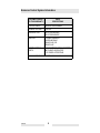
1
www.wackergroup.com
PETROL BREAKER
BH 23...
0109963en - 03.2004
0007891 101
0007892 101
0007893 101
0007894 101
Operator´s Manual
1.
Important information
This machine has been equipped with an EPA certified engine.
Additional information
manufacturers notes.
can
be
found
in
the
engine
WARNING
The engine exhaust from this product contains chemicals
known to the State of California to cause cancer, birth defects
or other reproductive harm.
Caution
This engine is an EPA engine.
Adjusting the engine speed will interfere with EPA certivication and
emissions.
Only authorized personnel can make adjustments to this engine.
Please contact you nearest Motor dealer or your Wacker Dealer for more
information.
T00940GB
1
T00940GB
2
Emission Control System Infor2.
Emission Control System Information
Source of Emissions
The combustion process produces carbon monoxide, oxides of
nitrogen, and hydrocarbons. Control of hydrocarbons and oxides of
nitrogen is very important because, under certain conditions, they
react to form photochemical smog when subjected to sunlight. Carbon
monoxide does not react in the same way, but it is toxic.
Wacker utilizes lean carburetor settings and other systems to reduce
the emissions of carbon monoxide, oxides of nitrogen, and
hydrocarbons.
The U.S. and California Clean Air Acts
EPA and California regulations require all manufacturers to furnish
written instructions describing the operation and maintenance of
emission control systems.
The following instructions and procedures must be followed in order to
keep the emissions from your Wacker engine within the emissions
standards.
Tampering and Altering
Tampering with or altering the emission control system may increase
emissions beyond the legal limit. Among those acts that constitute
tampering are:
•Removal or alteration of any part of the intake, fuel, or exhaust
systems.
•Altering or defeating the speed-adjusting mechanism to cause the
engine to operate outside its design parameters.
Problems That May Affect Emissions
If you are aware of any of the following symptoms, have your engine
inspected and repaired by your servicing dealer.
•Hard starting or stalling after starting.
•Rough idle.
•Misfiring or backfiring under load.
•Afterburning (backfiring).
•Black exhaust smoke or high fuel consumption.
T00953GB
3
Emission Control System Information
Replacement Parts
The emission control systems on your Wacker engine were designed,
built, and certified to conform with EPA and California emissions
regulations. We recommend the use of genuine Wacker parts
whenever you have maintenance done. These original-design
replacement parts are manufactured to the same standards as the
original parts, so you can be confident of their performance. The use
of replacement parts that are not of the original design and quality may
impair the effectiveness of your emission control system.
A manufacturer of an aftermarket part assumes the responsibility that
the part will not adversely affect emission performance. The
manufacturer or rebuilder of the part must certify that use of the part
will not result in a failure of the engine to comply with emission
regulations.
Maintenance
Follow the maintenance schedule. Remember that this schedule is
based on the assumption that your machine will be used for its
designed purpose. Sustained high-load or high-temperature
operation, or use in unusually wet or dusty conditions, will require more
frequent service.
OXYGENATED FUELS
Some conventional gasolines are being blended with alcohol or an
ether compound. These gasolines are collectively referred to as
oxygenated fuels. To meet clean air standards, some areas of the
United States and Canada use oxygenated fuels to help reduce
emissions.
If you use an oxygenated fuel, be sure it is unleaded and meets the
minimum octane rating requirement.
Before using an oxygenated fuel, try to confirm the fuel’s contents.
Some States / Provinces require this information to be posted on the
pump.
The following are EPA-approved percentages of oxygenates:
ETHANOL - (ethyl or grain alcohol) 10% by volume. You may use
gasoline containing up to 10% ethanol by volume. Gasoline containing
ethanol may be marketed under the name “Gasohol”.
MTBE - (methyl tertiary butyl ether) 15% by volume. You may use
gasoline containing up to 15% MTBE by volume.
T00953GB
4
Emission Control System InforMETHANOL - (methyl or wood alcohol) 5% by volume. You may use
gasoline containing up to 5% methanol by volume, as long as it
contains cosolvents and corrosion inhibitors to protect the fuel system.
Gasoline containing more than 5% methanol by volume may cause
starting and/or performance problems. It may also damage metal,
rubber, and plastic parts of your fuel system.
If you notice any undesirable operating symptoms, try another service
station, or switch to another brand of gasoline.
Fuel system damage or performance problems resulting from the use
of an oxygenated fuel containing more than the percentages of
oxygenates mentioned above are not covered under warranty.
Emission Control System Warranty
Your new Wacker engine complies with the U.S. EPA emissions
regulations. Wacker provides the same emission warranty coverage
for engines sold in all 50 states.
YOUR WARRANTY RIGHTS AND OBLIGATIONS
All States
Wacker must warrant the emission control system on your engine for
the period of time listed below provided there has been no abuse,
neglect or improper maintenance of your engine. Where a warrantable
condition exists, Wacker will repair your engine at no cost to you
including diagnosis, parts and labor.
Your emission control system may include such parts as the
carburetor, the ignition system and the catalytic converter.
Also included may be hoses, connectors and other emission-related
assemblies.
MANUFACTURER’S WARRANTY COVERAGE:
The 1998 and later engines are warranted for two years. If any
emission-related part on your engine is defective, the part will be
repaired or replaced by Wacker.
T00953GB
5
Emission Control System Information
OWNER’S WARRANTY RESPONSIBILITY:
As the engine owner, you are responsible for the performance of the
required maintenance listed in your owner’s manual. Wacker
recommends that you retain all receipts covering maintenance on your
engine, but Wacker cannot deny warranty coverage solely for the lack
of receipts or for your failure to ensure the performance of all
scheduled maintenance.
As the engine owner, you should be aware that Wacker may deny you
warranty coverage if your engine or a part has failed due to abuse,
neglect, improper maintenance or unapproved modifications.
You are responsible for presenting your engine to a Wacker dealer as
soon as a problem exists. The warranty repairs should be completed
in a reasonable amount of time, not to exceed 30 days.
If you have any questions regarding your warranty rights and
responsibilities, you should contact your local Wacker dealer.
WARRANTY COVERAGE:
Wacker engines sold after January 1, 1998, are covered by this
Emission Control System Warranty for a period of two years from the
date of delivery to the original retail purchaser. This warranty is
transferable to each subsequent purchaser for the duration of the
warranty period.
Warranty repairs will be made without charge for diagnosis, parts or
labor. All defective parts replaced under this warranty become
property of Wacker. A list of warranted parts is located on the next
page. Normal maintenance items, such as spark plugs and filters, that
are on the warranted parts list are warranted up to the required
replacement interval only.
Wacker is also liable for damages to other engine components caused
by a failure of any warranted parts during the warranty period.
Only Wacker approved replacement parts may be used in the
performance of any warranty repairs and must be provided without
charge to the owner. The use of replacement parts not equivalent to
the original parts may impair the effectiveness of your engine emission
control system. If such a replacement part is used in the repair or
maintenance of your engine, and an authorized Wacker dealer
determines it is defective or causes a failure of a warranted part, your
claim for repair of your engine may be denied. If the part in question is
not related to the reason your engine requires repair, your claim will not
be denied.
T00953GB
6
Emission Control System InforTO OBTAIN WARRANTY SERVICE:
You must take your Wacker product along with proof of original
purchase date, at your expense, to any Wacker authorized dealer
during their normal business hours. Claims for repair or adjustment
found to be caused solely by defects in material or workmanship will
not be denied because the engine was not properly maintained and
used.
EXCLUSIONS:
FAILURES OTHER THAN THOSE RESULTING FROM DEFECTS IN
MATERIAL OR WORKMANSHIP ARE NOT COVERED BY THIS
WARRANTY. THIS WARRANTY DOES NOT EXTEND TO
EMISSION CONTROL SYSTEMS OR PARTS WHICH ARE
AFFECTED OR DAMAGED BY OWNER ABUSE, NEGLECT,
IMPROPER MAINTENANCE, MISUSE, MISFUELING, IMPROPER
STORAGE,
ACCIDENT
AND/OR
COLLISION,
THE
INCORPORATION OF, OR ANY USE OF, ANY ADD-ON OR
MODIFIED PARTS, UNSUITABLE ATTACHMENTS, OR THE
UNAUTHORIZED ALTERATION OF ANY PART.
THIS WARRANTY DOES NOT COVER REPLACEMENT OF
EXPENDABLE MAINTENANCE ITEMS MADE IN CONNECTION
WITH REQUIRED MAINTENANCE SERVICES AFTER THE ITEM’S
FIRST SCHEDULED REPLACEMENT AS LISTED IN THE
MAINTENANCE SECTION OF THE PRODUCT OWNER’S MANUAL,
SUCH AS SPARK PLUGS AND FILTERS.
DISCLAIMER OF CONSEQUENTIAL DAMAGE AND LIMITATIONS
OF IMPLIED WARRANTIES:
WACKER DISCLAIMS ANY RESPONSIBILITY FOR INCIDENTAL
OR CONSEQUENTIAL DAMAGES SUCH AS LOSS OF TIME OR
THE USE OF THE POWER EQUIPMENT, OR ANY COMMERCIAL
LOSS DUE TO THE FAILURE OF THE EQUIPMENT; AND ANY
IMPLIED WARRANTIES ARE LIMITED TO THE DURATION OF THIS
WRITTEN WARRANTY. THIS WARRANTY IS APPLICABLE ONLY
WHERE THE
U.S. EPA EMISSION CONTROL SYSTEM
WARRANTY REGULATION IS IN EFFECT.
T00953GB
7
Emission Control System Information
SYSTEMS COVERED
BY THIS WARRANTY
PARTS
DESCRIPTIONS
FUEL METERING
CARBURETOR ASSEMBLY
EXHAUST SYSTEM
MUFFLER
AIR INDUCTION
AIR FILTER HOUSING
AIR FILTER ELEMENT*
IGNITION
FLYWHEEL MAGNETO
IGNITION MODULE
SPARK PLUG CAP
SPARK PLUG*
MISCELLANEOUS
PARTS
TUBING, FITTINGS, SEALS, GASKETS
AND CLAMPS ASSOCIATED
WITH THESE LISTED ITEMS
* Indicates expendable maintenance items.
T00953GB
8
Operating instructions
1.
Foreword
For your own safety and protection from bodily injuries, carefully read,
understand and follow the safety instructions in this manual.
Please operate and maintain your Wacker machine in accordance with
the instructions in this manual. Your Wacker machine will reward your
attention by giving trouble-free operation and a high degree of
availability.
Defective machine parts are to be replaced as soon as possible.
All rights, especially the right for copying and distribution are reserved
Copyright by Wacker Construction Equipment AG
No part of this publication may be reproduced in any form or by any
means, electronic or mechanical, including photocopying, without
express permission in writing from Wacker Construction Equipment AG.
Any type of reproduction, distribution or saving on data carriers of any
type or method not authorized by Wacker represents an infringement of
valid copyrights and will be prosecuted. We expressly reserve the right
to technical modifications - even without express due notice - which aim
at improving our machines or their safety standards.
9
Table of contents
1.
Important information
1
2.
Emission Control System Information
3
3.
Foreword
9
4.
Safety instructions
4.1
4.2
4.3
4.4
4.5
4.6
12
General ............................................................................................... 12
Operation ............................................................................................ 12
Safety checks ..................................................................................... 14
Maintenance ....................................................................................... 14
Transport ............................................................................................ 15
Maintenance checks ........................................................................... 15
5.
Technical Data
17
6.
Description
19
6.1
6.2
6.3
6.4
7.
Applications ........................................................................................ 19
Dimensions ......................................................................................... 19
Transport to work site ......................................................................... 20
Description of function ........................................................................ 20
Operation
7.1
7.2
7.3
7.4
7.5
21
Starting procedure .............................................................................. 21
Engine ................................................................................................ 21
During operation ................................................................................. 22
After operation .................................................................................... 22
Notes for correct working procedure .................................................. 23
10
Table of contents
8.
Maintenance
8.1
8.2
8.3
8.4
8.5
9.
25
Maintenance schedule ....................................................................... 25
Engine ................................................................................................ 26
Percussion system, crankcase ........................................................... 26
Assembly instructions ......................................................................... 27
Assembly ............................................................................................ 28
Labels
29
EC - Confornity Certificate
31
DIN EN ISO 9001 CERTIFICATE
33
11
Safety instructions
2.
Safety instructions
for the use of drilling and breaking hammers with combustion
engines
2.1
General
2.1.1
Drilling and breaking hammers may only be operated by persons who
∗
are at least 18 years of age,
∗
are physically and mentally fit for this job,
∗
have been instructed in operating drilling and breaking hammers and
proven their ability for the job to the employer
∗
may be expected to carry out the job they are charged with carefully.
The persons must be assigned the job of operating drilling and
breaking hammers by the employer.
2.2
SV00044GB
2.1.2
Drilling and breaking hammers are to be applied for their proper use.
Both the manufacturer’s operating instructions and these safety
instructions have to be observed.
2.1.3
The persons charged with the operation of these hammers have to be
made familiar with the necessary safety measures relating to the
machine. In case of extraordinary uses, the employer shall give the
necessary additional instructions.
2.1.4
It is possible that these drilling and breaking hammers exceed the
admissible sound level of 89 dB (A). According to the rules for the
prevention of accidents regarding emission of noise, the employees
have to wear ear protection if the sound level reaches 89 dB (A) or
more.
Operation
2.2.1
The function of operation levers or elements is not to be influenced or
rendered ineffective.
2.2.2
Before going on breaks, the operator has to switch of the engine and
has to place the drilling and breaking hammer in such a manner that it
cannot turn over.
2.2.3
Wear safety goggles in order to avoid injuries to the eyes.
2.2.4
We recommend wearing suitable working gloves.
12
Safety instructions
SV00044GB
2.2.5
Wear safety shoes while working with drilling and breaking hammers.
2.2.6
Drilling and breaking hammers are always to be operated with both
hands on the handles provided for this purpose.
2.2.7
When working with drilling and breaking hammers, especially when
carrying out drilling jobs, the operator has to have a firm stand,
particularly when working on scaffolding and ladders.
2.2.8
Drilling and breaking hammers are to be guided such that hand injuries
caused by solid objects are avoided. When carrying out demolition
jobs at elevated places, special care is required to prevent the machine
or the operator from falling.
2.2.9
Avoid body contact with earthed components. When breaking
connecting passages, make sure that there are no electric wires or gas
pipes. No one may stay in the room to which the passage is broken
through, as there is danger of injuries because of falling stones or
tools.
2.2.10
During operation the tool holder must be closed. Tools and tool holder
must be checked for wear in order to guarantee proper functioning of
holder.
2.2.11
The operation of this machine may cause broken - off pieces to be
flung away. Therefore, during operation, no one except the operator is
to come near this machine.
2.2.12
Switch off the engine of drilling and breaking hammers before
changing tools.
2.2.13
The tools always have to be in perfect conditions.
2.2.14
Do not smoke or handle open fire near this machine.
2.2.15
The tank lid must fit tightly. Shut fuel cock if available when stopping
the engine. For long distance transports of machines operated by fuel
of fuel-mixtures, the fuel tank has to be drained competely.
Leaky fuel tanks may cause explosions and must therefore be
replaced immediately.
13
Safety instructions
2.3
2.4
SV00044GB
2.2.16
Stop engine before filling fuel tank. When refilling fuel tank, do not
allow fuel to come into contact with the hot parts of the engine or spill
onto the ground.
2.2.17
Make sure that sufficient fresh air is available when operating drilling
and breaking hammers with combustion engines in enclosed areas,
tunnels, adits, and deep trenches. For this particular use we offer
drilling and breaking hammers with electrive drive.
2.2.18
Do not operate this machine in areas where explosions may occur.
Safety checks
2.3.1
Drilling and breaking hammers may only be operated with all safety
devices installed.
2.3.2
Before starting operation, the operator has to check that all control and
safety devices function properly.
2.3.3
Before starting operation, the overload clutch of drilling hammers has
to be checked for proper functioning.
2.3.4
In case of defects of the safety devices or other defects reducing the
operational safety of the drilling and breaking hammers, the supervisor
has to be informed immediately.
2.3.5
The machine must to be switched off immediately in case of defects
jeopardizing the operational safety of the equipment.
Maintenance
2.4.1
Only use original spare parts. Modifications to this machine, including
the adjustment of the maximum engine speed set by the manufacturer,
are subject to the express approval of WACKER. In case of
nonobservance all liabilities shall be refused.
2.4.2
Stop engine and pull off spark plug cap (if available) before carrying
out maintenance jobs, to avoid unintentional starting of the machine.
Deviations from this are only allowed if the maintenance job requires a
running engine.
2.4.3
Take care when checking the ignition system.
The electronic ignition system produces a very high voltage.
14
Safety instructions
2.4.4
All safety devices must be reinstalled properly immediately after
maintenance and repair jobs have been completed.
2.5
Transport
2.5.1
When being transported on vehicles, precautions have to be taken that
these hammers do not slip or turn over.
2.6
Maintenance checks
2.6.1
According to the conditions and frequency of use, drilling and breaking
hammers have to be checked for safe operation at least once a year
by skilled technicians, such as those found at WACKER-service
depots and have to be repaired if necessary.
Please also observe the corresponding rules and regulations valid in your
country.
SV00044GB
15
Safety instructions
SV00044GB
16
Technical Data
3.
Technical Data
BH 23
0007891
...
Item no.
Length x width x height (without tool)
mm:
0007892
...
790 x 450 x 333
23
kg:
ø 27x80
Percussion rate
min-1:
Single drill work
(at tip of tool)
0007894
...
845 x 450 x 333
Operating weight (mass) without tool
Shaft for breaking tools
0007893
...
SW
25x108
SW
28x152
SW
28x160
1300 - 1330
55 (5,5)
J (mkp):
Power transmission
From engine via centrifugal clutch, crank
mechanism, spring-loaded percussion system to
tool
Drive motor
2-stroke petrol engine
Displacement
Engine speed
cm3:
80
min-1:
4250
Special lubricating grease
grease Unirex N2
Fuel
Pol mixture-Petrol:
1:50 (1:100)
Fuel consumption
l/h:
1,2
l:
1,8
Tank capacity
Sound pressure level at operators station
LPA:
The weighted effective acceleration value, determined according to EN ISO 5349
m/s2:
TD00656GB
17
101 dB(A)
is 8,5
Technical Data
TD00656GB
18
Description
4.
Description
4.1
Applications
4.1.1
4.2
For breaking concrete and asphalt as well as rubble-laden ground, for
demolishing concrete, masonry and similar building materials
(undisturbed and frozen ground) etc., for ripping up roads and
concrete, asphalt, tar as well as wood-block and stone paving, for
cutting off clay, loam, turf and salts, for breaking compacted or tamped
ground, for ramming in posts and earth rods.
Dimensions
BH 23 ø 27x80
BH 23 SW 25x108
BH 23 SW 28x152
BH 23 SW 28x160
T00931GB
A
B
C
D
E
657
“
“
“
450
“
“
“
333
“
“
“
318
“
“
“
790
“
845
“
19
Description
4.3
Transport to work site
Conditions:
∗
Only use appropriate lifting gear with a minimum load-bearing capacity
of 30 kg when transporting the Wacker equipment.
∗
Always switch off motor during transport!
∗
Tie down the Wacker equipment when transporting it on the loadcarrying surface of a transport vehicle.
Note: Also refer to the specifications in safety instruction.
4.4
T00931GB
Description of function
4.4.1
The engine, which is flanged to the crankcase and is held in place by
3 screws. drives the percussion systemover a gear transmission and
a connecting rod. The engine torque is transmitted by means of a
centrifugal clutch.
4.4.2
The centrifugal clutch interrupts the flow of power to the percussion
system at low engine speeds, thus allowing for a perfect idling of the
engine.
4.4.3
The engine can be switched off with the stop button or the fuel tap.
4.4.4
The drive engine works according to the 2-stroke principle, and is
started mechanically by means of a recoilstarter. The engine is air
cooled and the air necessary for combustion is directed through the air
filter.
20
Operation
5.
Operation
5.1
Starting procedure
5.1.1
Attaching the tool
∗
Swing catch (9) at tool holder (11) outwards.
∗
Clean shank (10) and grease slightly.
∗
Insert tool as far as possible.
∗
Press catch (9) back against tool holder (11).
Only use sharp tools!
Only use tools with shank (10) in perfect conditions to avoid rebound
blows.
5.2
Engine
Fuel
Standard: 2 cycle oil/gasoline mixing ration of 1:50 or alternatively
1:100. Use 2-cycle engine oil of one of the following specifications:
NMMA TC-W3, API TC, JASO FC or ISO EGD. Unleaded gasoline
may aso be used!
Starting
Open fuel cock. If engine is cold close the choke at the carburettor.
Hold throttle control lever in middle position. Pull hard on starter rope
(max. 60 cm) until engine starts. Do not allow starter rope to snap
back. After starting engine open starter flap.
T00931GB
21
Operation
BESCHREIBUNG
Engaging clutch
Once the engine has warmed up push throttle to full position
(downwards).
Winter operation! Extremely low temperatures require 2-3 minutes
warming up of the engine at idling speed. As a result of the low
temperatures, grease will have stiffened in the system. To overcome
the difficulties arising from this, warm up the engine and lift the
machine several times, then put system into operation by quickly
opening the throttle.
5.3
During operation
Keep breaker dry and clean. Avoid no-load strokes. Never allow the
hammer to run with throttle wide open when forcing away broken or cut
off material or when lifting the hammer. When lifting the hammer, the
engine is decelerated by releasing the gas lever in the handle.
5.4
After operation
5.4.1
Short-term interruptions
Press stop button.
5.4.2
Finishing of breaking work
Close fuel cock. Allow engine to run until fuel in carburettor is used up.
5.4.3
Longer operational pauses
Clean hammer. Add corrosion preventative to fuel mixture and allow
engine to run for 5 minutes. Oil parts susceptible to rust.
T00931GB
22
Operation
5.5
Notes for correct working procedure
5.5.1
Set the petrol breaker with its tool against the material to be worked on
and start work by pressing down throttle.
5.5.2
Make use of the weight of the petrol breaker when working.
5.5.3
The performance of the tool is not improved by applying great pressure
against the material to be worked on.
5.5.4
A certain amount of pressure on the handles is necessary in order to
avoid no-load strokes and to ensure easy and agreeable handling.
5.5.5
Position the chisel in such a way as to be able to split off the material
to be worked on. This will prevent the tool from jamming, while
simultaneously improving the overall demolition efficiency.
T00931GB
23
Operation
T00931GB
24
Maintenance
6.
Maintenance
6.1
Maintenance schedule
Check all external screw connections for tight fit appox. 8 hours alfter first operation.
Component
Maintenance work
Air filter
Check for external damage and tight fit.
Fuel
Check tank lid for tight fit, replace if
necessary.
Miscellaneous
Check Bowden cable for smooth running.
Tools
Check shafts and cutting edges - if necessary
sharpen, reforge or replace.
Air filter
Check filter cartridge, clean or replace if
necessary.
Maintenance
interval
daily
Cylinder
Cooling fins dirt-free - if necessary, clean-dry.
Ignition
Clean spark plug, check spark plug gap (0,5 mm)
Check tool holder for wear - replace if
necessary.
weekly
monthly
Regrease via grease nipples.
20 hours
Check antifatigue shaft bolts for tight fit - retighten if
necessary - 75 Nm.
80 hours
Regrease crankshaft drive.
600 hours
Miscellaneous
T00932GB
25
Maintenance
6.2
6.3
Engine
6.2.1
Air filter: Clean by means of tapping or blowing (inside out). Do not use
petrol or any similar cleaning agents. Change heavily soiled filters or
filters already cleaned several times. Check filter seat before
assembly.
6.2.2
Fuel system and carburettor: Clean parts regularly, blow jets through.
6.2.3
Spark plug: Clean dirty or wet spark plugs. Check spark plug gap (0,5
mm).
6.2.4
Ignition: Gap between fan 0,3 - 0,4 mm.
6.2.5
Cylinder: Keep cooling fins clean.
6.2.6
Rewind starter: Oil bearing bolt lightly after approx. 200 hours of
operation.
Percussion system, crankcase
Lubricante (see technicla data)
Grease check
T00932GB
6.3.1
Grease breaker once a month by way of the red grease fitting of the
crankcase.
6.3.2
Renew grease in bearings of crank mechanism every 600 hours of
operation. Wash bearings thoroughly in appropiate cleaning fluid and
fill approx. 2/3 full with grease. Make sure not to fill in a greater or
lesser amount than that specified.
26
Maintenance
6.4
Assembly instructions
Disassembly
6.4.1
Percussion system
Remove both necked-down screws. Now tool holder and guide
cylinder can be removed. To remove the percussion system (striker
piston and guide piston with connecting rod) detach connecting rod in
crankcase. Attention! The connecting rod can only be disassembled if
the bearing flange has been removed.
6.4.2
Engine hood and tank
First remove the fuel cock lever by pulling it off. Remove the two
securing nuts holding down the air filter and then pull off the filter.
Disconnect the Bowden cable at the carburettor flange and pull off fuel
hose from the carburettor. Then proceed to remove the 4 screws
holding down the fuel tank and the 5 screws of the engine hood halves.
Then pull hood halves off the trunions of the spring mounting arms.
6.4.3
Oscillating suspension unit
Unhook springs, remove studs.
6.4.4
Engine
The engine can only be taken off the crankcase if the tank and the
engine hood have been previously taken off. Remove the 3 fastening
screws and pull engine with centrifugal clutch from the crankcase.
6.4.5
Starter
∗
Detach starter from engine.
∗
Remove hexagon nut, remove elastic washer and guide disk.
∗
Remove torsion spring, catch.
∗
Wind up starter rope anti-clockwise and place return spring under
tension by 1-2 rotations of the rope sheave.
∗
Remove rope sheave and return spring.
Access to the ignition system
Remove raised countersunk head screw, remove fan hood with
starter, remove the ignition armature by loosening the screws. Use
extractor to remove fan wheel.
T00932GB
27
Maintenance
Centrifugal clutch
Do not start disassembled engine before clutch is removed.
6.4.1
Crankcase
To disassemble the crankcase remove the 4 fastening screws at the
bearing flange and then remove the bearing flange with the crank gear
from the crankcase. Press crank gear out of bearing flange with screws
(outer borings), remove safety ring and then press out the bearing with
screws (inner borings). Press the centrifugal clutch drum axially out of
the crankcase.
6.5
Assembly
For assembly, proceed in reverse order. The following has to
be observed in particular:
T00932GB
∗
Keep centrifugal clutch drum and clutch free from grease.
∗
Seal off areas between crank case and bearing flange plus crank case
and guide cylinder with Omni-Visc, Type 1002.
∗
Wash out bearings and regrease.
∗
Fill inside of Nilos ring and space in the crank gear with grease.
∗
Grease the O-ring at the tool holder.
∗
Tighten the necked-down screws at the tool holder with 75 Nm (7,5
kpm).
∗
Tighten the oscillating suspension unit studs with 40 Nm and secure
with Omnifit 100M.
∗
Assemble connecting rod with flattened-down ribs in direction of crank
gear: (counterweight should not graze connecting rod).
28
Labels
7.
Labels
1
Decal - Information sign
2
Decal - Information sign
3
Decal - EPA
4
Decal - Sound power level
5
Ear protection decal
SK00642GB
29
Labels
SK00642GB
30
EC - Confornity Certificate
Wacker Construction Equipment AG , Preußenstraße 41, 80809 München
hereby certify that the construction equipment specified hereunder:
1. Category:
Breakinghammer
2. Type:
BH 23
3. Equipment item number:
0007891 ..., 0007892 ..., 0007893 ..., 0007894 ...
4. Operating weight:
23 kg
has been evaluated in conformity with Directive 2000/14/EC:
Conformity
assessment procedure
At the following notified
body
Annex VIII
VDE Prüf- und
Zertifizierungsinstitut
Zertifizierungsstelle
Merianstraße 28
63069 Offenbach/Main
Measured sound
power level
Guaranteed sound
power level
108 dB(A)
109 dB(A)
and has been manufactured in accordance with the following directives:
File certificate carefully
* 2000/14/EG
* 89/336/EG
* 98/37/EG
Dr. Sick
Board of Directors
C0006304GB
DIN EN ISO 9001 CERTIFICATE