1
B&K Components Device Interface Protocol
(BKC-DIP) Specification
Version 2.01.00
B&K Components Device Interface Protocol (BKC-DIP) Specification
Version 2.01.00
Updated 01/24/07
Page 1 of 54
Table of Contents
REVISION HISTORY ...................................................................................................................... 5
Version 2.01.00 .............................................................................................................................................. 5
Version 2.00.00.............................................................................................................................................. 5
Version 1.02.01.............................................................................................................................................. 5
Version 1.02.00.............................................................................................................................................. 5
Version 1.01.xx.............................................................................................................................................. 5
INTRODUCTION ............................................................................................................................. 6
Overview........................................................................................................................................................ 6
Document Conventions ................................................................................................................................ 6
Product Specific Appendices ....................................................................................................................... 6
Supported RS-232 Settings .......................................................................................................................... 6
Basic Protocol Syntax................................................................................................................................... 6
Begin/End Message Characters () .............................................................................................................. 7
ID, Receive or Transmit ............................................................................................................................. 7
Delimiter Character , .................................................................................................................................. 7
Checksum Delimiter ; ................................................................................................................................. 7
Identifier SubIdentifier Delimiter ............................................................................................................... 8
Checksum ................................................................................................................................................... 8
Tag Delimiter : ........................................................................................................................................... 9
NEW FEATURES OF BKC-DIP V2.0 VS. V1.0 ............................................................................ 10
8 alpha-numeric character tags ................................................................................................................. 10
Changes to the Parser Allowing “ , : ; ( ) in Strings................................................................................ 10
Parser Synchronization ............................................................................................................................. 10
Additional Intelligence require in Host Parser ......................................................................................... 11
SubIdentifiers Indicating Hardware Zone information.......................................................................... 12
Zone Specific specifier................................................................................................................................ 12
Macro specifier ........................................................................................................................................... 12
Macro Trigger Command.......................................................................................................................... 12
Favorite Settings of a Preset...................................................................................................................... 12
B&K Components Device Interface Protocol (BKC-DIP) Specification
Version 2.01.00
Updated 01/24/07
Page 2 of 54
Additional Reply Display formats............................................................................................................. 13
SUMMARY OF BKC-DIP COMMANDS ....................................................................................... 14
Host to B&K Device Commands Summary ............................................................................................. 14
G (get) command ...................................................................................................................................... 14
S (set) Command ...................................................................................................................................... 14
D (display) Command .............................................................................................................................. 15
X (executive) Command ........................................................................................................................... 15
B&K Device to Host Commands Summary ............................................................................................. 16
E (echo) Command................................................................................................................................... 16
R (reply) Command .................................................................................................................................. 16
U (update) Command ............................................................................................................................... 16
HARDWARE ZONES AND GROUPS .......................................................................................... 17
Hardware Zones ......................................................................................................................................... 17
Groups......................................................................................................................................................... 17
Code Sets, Zone IDs, and Logical Zones ................................................................................................. 18
Code Sets.............................................................................................................................................. 18
Zone IDs............................................................................................................................................... 18
Logical Zones....................................................................................................................................... 19
Groups and Linking Hardware Zone Control......................................................................................... 19
Default CT 610 Example .......................................................................................................................... 20
More Complicated CT 610 Example........................................................................................................ 21
SubIdentifiers.............................................................................................................................................. 22
HOST TO B&K DEVICE COMMANDS ......................................................................................... 25
G (get) Command ....................................................................................................................................... 25
Presets: (receiveID, G, Pz=nn, identifier, ... identifier; cs16) ................................................................... 25
System Settings: (receiveID, G, S, identifier, ... identifier; cs16) ............................................................ 26
Zone Adjustment (Hardware Special) Settings: (receiveID, G, H, identifier, ... identifier; cs16)............ 26
Zone Specific Settings: (receiveID, G, Zzz, identifier, ... identifier;cs16)................................................ 26
Macro Settings: (receiveID, G, Mt=mm, identifier, ... identifier;cs16) .................................................... 27
All Macro Settings: (receiveID, G, Mt, identifier, ... identifier;cs16) .................................................. 27
Tuner Station Settings: ( receiveID, G, Tnn, identifier, ... identifier;cs16) ............................................... 27
Realtime Status: (receiveID, G, R, identifier, ... identifier; cs16)............................................................. 28
Override Settings: (receiveID, G, O, identifier, ... identifier;cs16) .......................................................... 29
Display Content: (receiveID, G, D, d;cs16).............................................................................................. 29
Format Specification: (receiveID, G, Ff; cs16) ........................................................................................ 29
Error Log Status: (receiveID, G, E, identifier, ... identifier; cs16) ........................................................... 31
Favorite Settings of a Preset: (receiveID, G, A, identifier, ... identifier; cs16) ........................................ 31
S (set) Command ........................................................................................................................................ 32
Presets: (receiveID, S, Pz=nn, identifier = value, ... identifier = value; cs16) .......................................... 32
System Settings: (receiveID, S, S, identifier=value,...identifier=value; cs16).......................................... 33
B&K Components Device Interface Protocol (BKC-DIP) Specification
Version 2.01.00
Updated 01/24/07
Page 3 of 54
Zone Adjustment (Hardware Special) Settings: (receiveID, S, H, identifier=value,...identifier=value;
cs16) ......................................................................................................................................................... 33
Zone Specific Settings: (receiveID, S, Zzz, identifier = value, ... identifier = value; cs16)...................... 34
Macro Settings: (receiveID, S, Mt, identifier = value, ... identifier = value; cs16) .................................. 34
Serial Macro ......................................................................................................................................... 34
Escape Characters in Serial Macros ................................................................................................. 34
IR Macro............................................................................................................................................... 35
Tuner Station Settings: ( receiveID, S, Tnn, identifier = value, ... identifier = value; cs16)...................... 35
Favorite Settings of a Preset: (receiveID, S, A, identifier=value, ... identifier=value; cs16) ................... 35
Override Settings: (receiveID, S, O, identifier=value,...identifier=value; cs16) ...................................... 36
Override Timeout ................................................................................................................................. 37
IR Command: (receiveID, S, I, z=ir; cs16) .............................................................................................. 38
Front Panel Commands: (receiveID, S, F, z=fp; cs16) ............................................................................. 38
Error Logs: (receiveID, S, E, identifier=value,...identifier=value; cs16) ................................................. 38
D (display) Command ................................................................................................................................ 39
On Screen Display (O): (receiveID, D, O, Ttt, Mm, Xcc, Yrr, "text", ... Xrr, Ycc, "text"; cs16)(only
applicable to units with On Screen Display capabilities) ......................................................................... 39
Front Panel Display (F): (receiveID, D, F, Ttt, Xcc, Yrr,"text";cs16)...................................................... 40
LED display: (receiveID, D, L, Ttt, n=bitmap; cs16) .............................................................................. 41
X (executive) Command............................................................................................................................. 42
M (Macro Trigger) Command: (receiveID, M, t=mm, … ,t=mm;cs16) ............................................... 43
B&K DEVICE TO HOST COMMANDS ......................................................................................... 44
E (echo) Command..................................................................................................................................... 44
Implementing Software Flow Control using Echo Commands ................................................................ 44
R (reply) Command.................................................................................................................................... 44
Reply from the Get Display command (transmitID, G, D, d; cs16) ......................................................... 45
BKC-DIP V1.0 Compliant Display Reply............................................................................................ 46
BKC-DIP V2.0 Compliant Display Reply without Attributes.............................................................. 47
BKC-DIP V2.0 Compliant Display Reply with Attributes ................................................................... 48
U (update) Command................................................................................................................................. 50
Status message: (transmitID, U, S, n=“status message”;cs16)................................................................. 50
BKC-DIP Active message: (transmitID, U, S, 0=“BKC-DIP ACTIVE”;cs16) ................................... 50
IR message: (transmitID, U, I, z=ir;cs16) ................................................................................................ 51
Front Panel message: (transmitID, U, F, z=ir;cs16)................................................................................. 51
Realtime Status message: (transmitID, U, R, identifier=value;cs16) ....................................................... 51
USE OF RECEIVE AND TRANSMIT IDS..................................................................................... 53
The Receive ID............................................................................................................................................ 53
The Transmit ID......................................................................................................................................... 53
A Multiple Unit Example ........................................................................................................................... 53
B&K Components Device Interface Protocol (BKC-DIP) Specification
Version 2.01.00
Updated 01/24/07
Page 4 of 54
Revision History
Version 2.01.00
1.
Add new Hardware Special Format (receiveID,G,F9;).
Version 2.00.00
1.
2.
3.
4.
New version of BKC-DIP with expanded capabilities and support for multi-hardware zone
devices. See section New Features of BKC-DIP V2.0 vs. V1.0 for details.
Override Parameters have diverged to be specific per product. Moved Override Parameters
section to Product Specific Appendices’ Appendix P.
Status Update Messages have been moved to the Product Specific Appencies’ Appendix Q
and further detailed.
Additional Format Specifiers have been added to support new commands. Refer to Format
Specification: (receiveID, G, Ff; cs16) for more detail.
Version 1.02.01
1.
2.
3.
Corrected examples for Set OSD Display command.
Corrected note regarding valid OSD row range.
Added note about 16:9 Aspect ratio interaction with OSD Display row specification.
Version 1.02.00
1.
2.
This is the first version of this documentation which is specified by version number.
This document includes augmentation to the original BKC-DIP V1.01 protocol and
supercedes information found in “B&K Components Device Interface Protocol (BKC-DIP)
V1.01 Protocol Document”.
Version 1.01.xx
1.
Documentation earlier than Version 1.02.00 was not specified by a version number. This
encompasses all documentation prior to 08/07/00. Prior documentation entitled “B&K
Components Device Interface Protocol (BKC-DIP) V1.01 Protocol Document” described
BKC-DIP Version 1.01 is therefore referred to as Version 1.01.xx here.
B&K Components Device Interface Protocol (BKC-DIP) Specification
Version 2.01.00
Updated 01/24/07
Page 5 of 54
Introduction
Overview
The following is the specification and implementation details of the B&K Components Device
Interface Protocol, BKC-DIP. BKC-DIP is an ASCII text based serial protocol. The electrical
specification is RS-232, thus B&K Components' devices may be controlled by standard "COM"
ports or similar serial devices. Through the use of Receive and Transmit IDs, multiple B&K
Components units may be controlled on a common serial bus.
Document Conventions
All numbers are assumed to be hexadecimal. Hexadecimal (or Hex for short) characters range
from 0 to F.
For example:
1
0
The number 19 is the hexadecimal number 19 which is (1 x 16 ) + (9 x 16 ) or
1
25 decimal. Similarly, EA is the hexadecimal number EA which is (14 x 16 ) +
0
(10 x 16 ) or 234 decimal. For clarity, some descriptions regarding numbers
may use the xxh notation to remind the reader that the number is implicitly
hexadecimal where xx are the hexadecimal characters 0 - F. Thus the previous
examples would be 19h and EAh respectively, the "h" indicating hexadecimal.
Italics indicate a non-literal string.
For example:
(00,G, P00, 0;cs16)
cs16 indicates the calculated checksum and does NOT literally appear in the
data stream.
Important concepts are denoted by NOTE:
Product Specific Appendices
Although all RS-232 capable B&K Components’ devices support the BKC-DIP protocol,
implementation details vary according to product family. The examples used in this document are
based on the CT 610 and REF 30 products. Make sure to consult the product specific appendices
for the specific B&K Components’ unit being controlled.
Supported RS-232 Settings
The currently supported baud rates are:
1200, 2400, 9600, 14400, 19200, 28800, 38400, 57600, and 115200
The currently supported serial settings are N-8 -1:
N, no parity
8, eight bit data
1, one stop bit
Hardware flow control is not supported.
Basic Protocol Syntax
The B&K Components Device Interface Protocol (BKC-DIP) is an ASCII text based serial
protocol. All commands follow the same basic format:
B&K Components Device Interface Protocol (BKC-DIP) Specification
Version 2.01.00
Updated 01/24/07
Page 6 of 54
(id, cc, ss, ... ; cs16)
where:
(
id
,
cc
,
ss
;
cs16
)
indicates the start of a message
is the Receive ID (for host to B&K unit commands) or Transmit ID (for B&K
unit to host commands)
is the delimiter character
is the command
is the delimiter character
is the command specifier
is the checksum delimiter
is 16-bit (optional, but recommended) checksum
indicates the end of a message
NOTE: Leading zeros may be omitted.
NOTE: Upper and lower case characters may be used interchangeably. (00,G, P01; 01EB ) is
equivalent to (00,g, p1; 1FB )
Begin/End Message Characters ()
The ASCII open/close parenthesis characters "(" and ")" not occurring in a double quoted string
indicate the beginning and the end of a BKC-DIP message respectively.
NOTE: Each time an open parenthesis character not occurring in a double quoted string is
received, the parsing engine's state is reset. In the event of the host and B&K
Component's device loses sync, the "(" will abort any previous state and the
communication will once again be in sync except under conditions detailed in New
Features of BKC-DIP V2.0 vs. V1.0.
ID, Receive or Transmit
The first token of each BKC-DIP message is an ID, which can be 00h – 7Fh. This allows up to
128 different units to be controlled on the same serial bus.
NOTE: The receive ID FFh is also supported as a “global” or “universal” receive ID. Any B&K
Components device on a serial channel would respond to commands with a receive ID of
FFh regardless of their specified receive ID. This is useful for determining if any B&K
Components devices are on a particular serial channel.
See section entitled Use of Receive and Transmit IDs for more details.
Delimiter Character ,
All members of a BKC-DIP message are delimited by "," an ASCII comma (with the exception of
the checksum delimiter ";", see below).
NOTE: Unlike V1.0 BKC-DIP, commas are allowed in double quoted strings (such as text
strings as in "Comma, IS valid"). Refer to New Features of BKC-DIP V2.0 vs. V1.0 for
details.
Checksum Delimiter ;
The checksum of each message is optionally transmitted embedded in the message to assure data
has not been corrupted during transmission. The checksum is the 4 digits hexadecimal digits (0-F)
directly following the ";" delimiter. Software designed to parse BKC-DIP serial streams can
easily detect the ";" delimiter, thus making message parsing simple.
B&K Components Device Interface Protocol (BKC-DIP) Specification
Version 2.01.00
Updated 01/24/07
Page 7 of 54
NOTE: Unlike V1.0 BKC-DIP, semi-colons are allowed in double quoted strings (such as text
strings as in "Semi-colon; valid"). Refer to New Features of BKC-DIP V2.0 vs. V1.0
for details.
Identifier SubIdentifier Delimiter
On units where multiple hardware zones can be “linked” using “Code Sets” to logical zones, such
as the CT 610, identifiers from the unit may have addition SubIdentifiers. These SubIdentifiers
are delimited from the identifier via an ASCII period, “.”.
An example reply which contains SubIdentifier Delimiters (and subsequently SubIdentifiers) is:
(0, R, G, P7=FF, 1.A=20, 1.B=18, 1.D.L=10; cs16)
This response containing Volume information for the current preset of Zone 7, P7=FF, indicates
that there are 3 different hardware zones attached to the logical zone 7.
NOTE: For an in depth discussion of Hardware Zones vs. Logical Zones, see section Hardware
Zones and Groups.
Checksum
The checksum itself is a 16 bit quantity calculated by summing all of the incoming ASCII
characters up to and including the ";" checksum delimiter AND excluding the begin message "(".
For example, the checksum for the following message would be calculated as:
(00, G, P00; 01EA)
(
0
0
,
G
,
P
0
0
;
begin message character, ignored in checksum calculation, reset checksum
checksum = checksum + 30h
checksum = checksum + 30h
checksum = checksum + 2Ch
checksum = checksum + 47h
checksum = checksum + 2Ch
checksum = checksum + 50h
checksum = checksum + 30h
checksum = checksum + 30h
checksum = checksum + 3Bh and signals to terminate checksum calculation and
that message checksum follows
Thus the calculated checksum would be 01EAh, which matches the message checksum indicating
the received message is valid and uncorrupted.
NOTE: The checksum is optional but strongly recommended to assure the integrity of the
transmitted data. If the checksum is not transmitted, the checksum delimiter is
immediately followed by the end message ")".
For example:
(00, G, P00;) The checksum 01EA has been omitted
NOTE: Whitespace appearing outside of quotes is ignored, and does not enter into the checksum
calculation.
B&K Components Device Interface Protocol (BKC-DIP) Specification
Version 2.01.00
Updated 01/24/07
Page 8 of 54
For example, the following two commands both yield the same checksum, 01DFh.
(00, G, P00; 01EA)
(00, G,
P00; 01EA)
However, the following two commands yield different checksums because of the whitespace in the
second title:
(00, S, P1, 0="Title";04A6)
(00, S, P1, 0=" Title ";04E6)
white space characters before and after Title
Tag Delimiter :
It is often useful to be able to determine which response from the B&K Component’s device
corresponds to a particular command issued by the host. To facilitate this, an optional tag may be
concatenated to the receive ID. This tag may be up to 8 alpha-numeric characters in length, and is
then concatenated to the transmit ID of the message(s) generated by the unit.
A few examples to demonstrate the use of the tag:
(0:1234wxyz, G, P3=1, 0;053D)
Get Z3 Preset 1, parameter 0 with tag
1234wxyz
(0:1234wxyz,E,G,P3=1,053D;065A)
Echo from unit with tag 1234wxyz
(0:1234wxyz,R,P3=1,0="His TV
";0897)Reply from unit with tag 1234wxyz
NOTE: The use of tags is optional. If no tag delimiter is detected in the received command, no
tag is appended in the response from the unit.
NOTE: Unlike V1.0 BKC-DIP, V2.0’s tag is 8 characters long, as opposed to only 4. Refer to
New Features of BKC-DIP V2.0 vs. V1.0 for details.
NOTE: Messages generated autonomously by the unit (such as “U” update commands) do not
have tags associated with them.
(0,U,I,1=24;0261)
Update IR command Z1 of 24 (Volume +), no tag
NOTE: Unlike V1.0 BKC-DIP, colons are allowed in double quoted strings (such as text strings
as in "Colon : valid"). Refer to New Features of BKC-DIP V2.0 vs. V1.0 for details.
B&K Components Device Interface Protocol (BKC-DIP) Specification
Version 2.01.00
Updated 01/24/07
Page 9 of 54
New Features of BKC-DIP V2.0 vs. V1.0
Several new features have been added to the BKC-DIP protocol. For those familiar with BKCDIP V1.0, this section concisely lists all the new features now available. For those just becoming
acquainted with BKC-DIP, you may want to note which features are not available in the B&K
Components devices with V1.0 BKC-DIP implementations.
NOTE: If using this document with a BKC-DIP V1.0 device, please remember that the following
features do not apply. This will NOT be explicitly noted throughout the remainder of the
documentation.
The changes from protocol V1.0 to V2.0 are listed below.
8 alpha-numeric character tags
The optional tag which can be appended to the receive ID with a colon, “:” has been increased to 8
alpha-numeric characters as opposed to 4.
Changes to the Parser Allowing “ , : ; ( ) in Strings
Perhaps the most important change to BKC-DIP V2.0 from V1.0 is the augmented support for
strings. In previous versions of BKC-DIP specific characters could only appear as protocol syntax
and were not allowed in any other context, specifically strings.
In adding the new Serial Macro feature (see the Macro specifier section below), it was desirable
to allow BKC-DIP commands to be emitted. This implied that entire BKC-DIP commands needed
to be supported as a valid BKC-DIP string, which further implied that BKC-DIP delimiters (i.e. “ ,
: ; ( ) ) NOT be interpeted inside double quoted strings.
This further implied the addition of the escape character “\”, backslash to allow double quotes and
the escape character itself to be embedded into strings.
A Serial Macro Set command follows as an example:
(0, S, M0=0, 0=1, 1=C4, 4=”(0:1234,S,P1=0,0=\”Title\”;)”;)
Notice the BKC-DIP command (0:1234,S,P1=0,0=”Title”;) as a string in the previous example.
Parser Synchronization
In V1.0 versions of BKC-DIP, any time the parser received an opening parenthesis, “(“, the parser
state machine was reset. This implied that no matter what characters had previously be sent to the
BKC-DIP device, sending a ( would begin a new BKC-DIP command.
The same still holds true with one very important exception: double quoted strings (which are
delimited by the ASCII character “, 34). The V2.0 BKC-DIP parser holds state regarding finding
a double quote character. When the parser finds a double quote it will not interpret any character
until it finds a matching unescaped double quote. This implies that the parser could get into a state
that a open parenthesis would not reset, namely if the parser is in the midst of a quoted string. The
following examples will illustrate.
Let’s assume that a user wanted to set Zone 1 Preset 0’s title to extremely clever and descriptive
word “Title”. The user began typing the following:
(0, S, P1=0, 0=”Pit
B&K Components Device Interface Protocol (BKC-DIP) Specification
Version 2.01.00
Updated 01/24/07
Page 10 of 54
It is then realized that the user has misspelled. With a V1.0 BKC-DIP parser, simply retyping the
command would correct the issue as the parser would be reset upon receiving the openning “(“.
However, that is not the case with the V2.0 parser, as the parser is currently in a state of
accumulating characters for the string <“Pit> (the < and > characters added for clarity). The
parser will not interpret the “(“ character as part of the BKC-DIP syntax, but merely more of the
string <”Pit(>.
Additional Intelligence require in Host Parser
When developing a BKC-DIP V2.0 parser additional intelligence must be incorporated so BKCDIP syntax is not interpreted when appearing in double quoted strings. The following is pseudo
code for the state machine for such a parser:
BeginCommandState
If the character = ‘(‘
Reset state (i.e. checksum calculation
Next state = GetReceiveIDState
GetReceiveIDState
Add the character to the checksum calculation
If the character = ‘,’ or ‘:’
Indicates last character of ReceiveID
If the character = ‘:’
Next state = GetTagState
Else
Next state = FillCommandBufferState
Else
Add the character to the ReceiveID
GetTagState
Add the character to the checksum calculation
If the character = ‘,’
Indicates last character of the tag
Next state = FillCommandBufferState
Else
Add character to the tag
FillCommandBufferState
Add the character to the checksum calculation
If the character = ‘“’
Next state = QuotedStringState
Add character to command buffer
Convert the character to upper case
If the character = ‘;’
Indicates checksum possibly coming
Next state = ChecksumState
Else if the character = ‘(‘
Next state = BeginCommandState
Add character to command buffer
QuotedStringState
B&K Components Device Interface Protocol (BKC-DIP) Specification
Version 2.01.00
Updated 01/24/07
Page 11 of 54
Add the character to the checksum calculation
If the character = ‘\’
Next state = CharacterEscapeState
Else if the character = ‘”’
Next state = FillCommandBufferState
Add character to command buffer
CharacterEscapeState
Add the character to the checksum calculation
Next state = QuotedStringState
Add character to command buffer
ChecksumState
If the character = ‘)’
Indicates completion of checksum
If checksum = calculated checksum or no checksum received
Further command parsing
Next state = BuildCommandState
Else
Add character to the checksum
SubIdentifiers Indicating Hardware Zone information
SubIdentifiers have been added to augment parameter identifiers to identify to which Hardware
Zone the values is associated. These take the form of “.A”, “.B”, “.C”, etc. for stereo Hardware
Zones and “D.L”, “D.R”, “E.L”, “E.R”, “F.L”, “F.R”, etc. for mono Hardware Zones. Please refer
to the Hardware Zones and Groups and SubIdentifiers sections later in this document for
further details about Hardware Zones, Logical Zones, and SubIdentifiers.
Zone Specific specifier
Since new multi-zone devices have varying number of Logical Zones (based upon the System
Settings for Zone IDs and Code Sets), the Zone Specific specifier, “Z”, has been added to Get and
Set commands. Please refer to sections Zone Specific Settings: (receiveID, G, Zzz, identifier, ...
identifier;cs16) and Zone Specific Settings: (receiveID, S, Zzz, identifier = value, ... identifier =
value; cs16) for more details.
Macro specifier
An additional specifier, M (for Macro), has been added to the Get and Set commands to allow
Serial Macro configuration. Please refer to sections Macro Settings: (receiveID, G, Mt=mm,
identifier, ... identifier;cs16) and Macro Settings: (receiveID, S, Mt, identifier = value, ...
identifier = value; cs16) for more details.
Macro Trigger Command
To allow BKC-DIP triggering of the new Macro features, the M command has been added to
BKC-DIP. This allows a specific Macro (type and number) to be triggered via BKC-DIP. Please
refer to M (Macro Trigger) Command: (receiveID, M, t=mm, … ,t=mm;cs16) section for more
details.
Favorite Settings of a Preset
To allow an easy mechanism to Get/Set the favorite of a particular presets across several Logical
Zones in a single command, the Favorite Command added to BKC-DIP. Please refer to Favorite
B&K Components Device Interface Protocol (BKC-DIP) Specification
Version 2.01.00
Updated 01/24/07
Page 12 of 54
Settings of a Preset: (receiveID, G, A, identifier, ... identifier; cs16) and Favorite Settings of a
Preset: (receiveID, S, A, identifier=value, ... identifier=value; cs16) for more details
Additional Reply Display formats
There are two new reply formats for Display Replies, in addtion to a BKC-DIP V1.0 compatible
format. See sections BKC-DIP V1.0 Compliant Display Reply, BKC-DIP V2.0 Compliant
Display Reply without Attributes, and BKC-DIP V2.0 Compliant Display Reply with
Attributes for more details.
B&K Components Device Interface Protocol (BKC-DIP) Specification
Version 2.01.00
Updated 01/24/07
Page 13 of 54
Summary of BKC-DIP Commands
The following is a summary of the BKC-DIP commands and some brief examples. Each
command is described in detail in the remainder of the document. The commands are broken in to
two categories: Host to B&K Device Commands and B&K Device to Host Commands.
Host to B&K Device Commands Summary
G (get) command
Presets: (receiveID, G, Pz=nn, <identifier, ... identifier>; cs16)
(0,G,P1=3,1,2,3;cs16)
Get Z1 Preset 3 parameters 1,2,3
(0,G,P2=7,4,5,6;cs16)
Get Z2 Preset 7 parameters 4,5,6
System Settings: (receiveID, G, S,<identifier, ... identifier>; cs16)
(0,G,S,0,1,5;cs16)
Get System parameters 0,1,5
Zone Adjustment (Hardware Special) Settings:
(receiveID, G, H,<identifier, ... identifier>; cs16)
(0,G,H,0,1,5;cs16)
Get System parameters 0,1,5
Zone Specific Settings: (receiveID, G, Zzz, identifier, ... identifier;cs16)
(00, G, Z0;0204)
Get Logical Zone 0’s settings.
Macro Settings: (receiveID, G, Mt=mm, identifier, ... identifier;cs16)
(00, G, M0=20;0296)
Get Serial Macro 32’s settings
(0,G,M0;0187)
Get All Serial Macros
Tuner Station Settings: (receiveID, G, Tnn, <identifier, ... identifier>;cs16)
(0,G,T12;cs16)
Get Tuner channel 18 all parameters
Realtime Status: (receiveID, G, R, <identifier, ... identifier>; cs16)
(0,G,R,3;cs16)
Get Realtime Status parameter 3
Override Settings: (receiveID, G, O, <identifier, ... identifier>; cs16)
(0,G,O,0;cs16)
Get Override parameter 0
Display Content: (receiveID, G, D, d;cs16)
(0,G,D,O; cs16)
Get current contents of the OSD
(0,G,D,F; cs16)
Get current contents of the front panel display
Error Log Status: (receiveID, G, E, <identifier,… identifier>;cs16)
(0,G,E,1;cs16)
Get unused RAM Error Log status
Format Specification: (receiveID, G, Ff; cs16)
(0,G,F1=0;cs16)
Get Z1 Preset Format
(0,G,F2=0;cs16)
Get Z2 Preset Format
(0,G,F1;cs16)
Get System Format
(0,G,F2;cs16)
Get Tuner Format
(0,G,F3;cs16)
Get Realtime Format
(0,G,F4;cs16)
Get Unit Specifier
(0,G,F5;cs16)
Get Override Format
(0,G,F6;cs16)
Get Error Log Format
(0,G,F1=7;cs16)
Get Z1 Zone Specific Format
(0,G,F0=8;cs16)
Get Type 0 Macro Format
(0,G,F9;cs16)
Get Zone Adjustment (Hardware Special) Format
Favorite Settings of a Preset: (receiveID, G, A, identifier, ... identifier; cs16)
(0,G,A=10;01E9)
Get Favorite Settings of Preset 10h (16 decimal)
S (set) Command
Presets: (receiveID, S, Pz=nn, identifier = value, ... identifier = value; cs16)
(0,S,P1=B,0=”My Title”;cs16)
Set Z1 Preset 11 parameter 0
(0,S,P2=4,1=60,2=18;cs16)
Set Z2 Preset 4 parameters 1, 2
System Settings: (receiveID, S, S, identifier=value,...identifier=value; cs16)
(0,S,S,0=”LASER”,9=15;cs16)
Set System parameters 0 and 9
B&K Components Device Interface Protocol (BKC-DIP) Specification
Version 2.01.00
Updated 01/24/07
Page 14 of 54
Zone Adjustment (Hardware Special) Settings:
(receiveID, S, H, identifier=value,...identifier=value; cs16)
(0,S,H,00=00,09=15;cs16)
Set Zone Adjustment parameters 0 and 9
Zone Specific Settings: (receiveID, S, Zzz, identifier = value, ... identifier = value; cs16)
(1, S, Z7, 0=”Living Room”;cs16) Set Z7 Zone title
Macro Settings: (receiveID, S, Mt, identifier = value, ... identifier = value; cs16)
(0,S,M0=A,5=”(0,S,S,0=\”Laser\”;)”;)
Set Serial Macro
Tuner Station Settings: (receiveID, S, Tnn, identifier = value, ... identifier = value; cs16)
(0,S,T04,1=20;cs16)
Set Tuner Channel 4 parameter 1
Override Settings: (receiveID, S, O, identifier = value, ... identifier = value; cs16)
(0,S,O,0=1;cs16)
Set Override parameter 0
IR Command: (receiveID, S, I, z=ir; cs16)
(0,S,I,2=C4;cs16)
Set IR Zone 2 command C4
Front Panel Commands: (receiveID, S, F, z=fp; cs16)
(0,S,F,1=0A;cs16)
Set Front Panel Zone 1 command A
Error Log Status: (receiveID, G, E, <identifier = value,… identifier = value>;cs16)
(0,S,E,1=0;cs16)
Clear unused RAM Error log status
Favorite Settings of a Preset: (receiveID, S, A, identifier=value, ... identifier=value; cs16)
(0,S,A=10,0=1,3=1,4=0; 0459 )
Set Preset 16 favorite in Z0 and Z3, not Z4
D (display) Command
OSD (O): (receiveID, D, O, Ttt, Mm, Xcc, Yrr, "text", ... Xrr, Ycc, "text"; cs16)
(0,D,O,T64, M0, X02, Y04, "Hello World";cs16)
T64
will clear the display after 64h * 100ms (10seconds)
M0
text displayed over background color "blue screen"
X02
displayed text will start at row 02h (the third row)
Y04
displayed text will start at column 04h (the fifth column)
Front Panel Display (F): (receiveID, D, F, Ttt, Xcc, Yrr,"text";cs16)
(0,d, f, t0, x0, y2, "Testing";cs16)
t0
display will NOT be clear by a timeout
x0
displayed text will start at row 00h (the first row)
y2
displayed text will start at column 02h (the third column)
LED display: (receiveID, D, L, Ttt, n=bitmap; cs16)
(00, D, L, T00, 1=21; 0360)
Set DOWN and REAR LEVEL LED on
X (executive) Command
NOTE: Please refer to the Appendix L of the appropriate Product Specific Appendices to note
implimentation details and of the executive commands.
Recall Preset Command: (receiveID, X, 0, z=nn; cs16)
(0,X,0,1=4;cs16)
Recall Z1 Preset 4 to current preset
Save Preset Command: (receiveID, X, 1, z=nn; cs16)
(0,X,1,2=9;cs16)
Save current preset to Zone 2 Preset 9
Power State Command: (receiveID, X, 2, z=onOff; cs16)
(0,X,2,1=1;cs16)
Turn Z1 power on
(0,X,2,2=0;cs16)
Turn Z2 power off
Noise Generator State Command: (receiveID, X, 3, onOff; cs16)
(0,X,3,1;cs16)
Activate noise generator
(0,X,3,0;cs16)
Deactivate noise generator
Noise Steering Command: (receiveID, X, 4, index=onOff…, index=onOff; cs16)
(0,X,4,0=1,1=1,5=1;cs16)
Noise output Left Front, Center, and Sub
Noise Increment Command: (receiveID, X, 5; cs16)
(0,X,5;cs16)
Increment noise output to next valid channel
B&K Components Device Interface Protocol (BKC-DIP) Specification
Version 2.01.00
Updated 01/24/07
Page 15 of 54
Cold Boot Command: (receiveID, X, 6; cs16)
(0,X,6;cs16)
Cold Boot BKC-DIP device
Factory Reset Command: (receiveID, X, 7; cs16)
(0,X,7;cs16)
Factory Reset BKC-DIP device
WARNING!:
Issuing a Factory Reset Command will destroy all user
modified data in the unit (preset, system settings, etc.).
Reinitialize BKC-DIP State Command: (receiveID, X, 8; cs16)
(0,X,8;cs16)
Reinitialize BKC-DIP State parameters
Test Tone State Command: (receiveID, X, 9, level; cs16)
(0,X,9,2;cs16)
Test Tone on at –30.0 dB level
(0,X,9,0;cs16)
Test Tone off
Mute State Command: (receiveID, X, A, z=muteState; cs16)
(0,X,A,1=1;cs16)
Mute Z1
(0,X,A,2=0;cs16)
Unmute Z2
B&K Device to Host Commands Summary
E (echo) Command
(2, E, G, P1=00, 0228;0393)
Echo from unit 02h for Get Z1 Preset 0 command
R (reply) Command
(2, R, P2=1,3=5;02D8)
Reply from unit 02h Z2 Preset 1 parameter 3 info
(0, R, D, F, 0="X FRONT PANEL XX
",80=1;cs16)
Reply from the Get Display command (transmitID, G, D, d; cs16)
U (update) Command
Status message: (transmitID, U, S, 0=“BKC-DIP ACTIVE”;cs16)
(0,U,S,0=”BKC-DIP ACTIVE”;cs16)
Ready for BKC-DIP commands
IR message: (transmitID, U, I, z=ir;cs16)
(0,U,I,1=C4;cs16)
Update to host from Zone 1 <Volume ->
Front Panel message: (transmitID, U, F, z=ir;cs16)
(0,U,F,1=A;cs16)
Update to host from Zone 1 front panel <Volume ->
Realtime Status message: (transmitID, U, R, identifier=value;cs16)
(0,U,R,5=sample rate;cs16)
Update from sample rate change
B&K Components Device Interface Protocol (BKC-DIP) Specification
Version 2.01.00
Updated 01/24/07
Page 16 of 54
Hardware Zones and Groups
In recent B&K Components’ devices, such as the CT 610, there is the concept of Hardware Zones,
Groups, and Logical Zones. This has implications with regards to BKC-DIP. In order to
understand these parts of BKC-DIP, an understanding of Hardware and Software zones is
required. This section describes the concepts of Hardware Zones, assignment of Groups to link
command and control of Hardware Zones to form Logical Zones, and SubIdentifiers (which is
how BKC-DIP presents Hardware Zone information).
NOTE: References to the B&K Components CT 610 will be used as examples since it is the first
B&K product to contain these features. Again, recall that BKC-DIP V1.0 is a subset of
V2.0x features. Thus this section has no meaning in BKC-DIP V1.0 products.
Hardware Zones
As the name implies, Hardware zones relate to hardware. Thus a Hardware zone can be thought
of as the output jacks of the Device. On the CT 610, for example, there are 6 (stereo) output zones
lettered A – F. In some instances a stereo zone can be “split” into 2 mono zones which are further
subspecified by “.L” or “.R” referring to the left or the right half respectively.
NOTE: Hardware Zones are referred to by uppercase letter. For example, in the CT 610, the
6 stereo zone outputs are referred to as A, B, C, D, E, and F respectively. As another
example, if all 6 zones of a CT 610 were configured to be mono zones, they would be
referred to as A.L, A.R, B.L, B.R, C.L, C.R, D.L, D.R, E.L, E.R, F.L, and F.R
respectively.
Groups
As the name implies, Groups relate to how Hardware Zones are to be linked and controlled. In the
CT 610 and CT 310, we introduce the concept of Groups. Group is simply a method used to link
command and control of one Hardware Zone, or many Hardware Zones, using a single Code
Set/Zone ID. Currently, the CT 610 and CT 310, supports 18 groups. Groups are referred to by
lowercase letters a – r. There also exists a Whole House Group that is always set for use with Code
Set/Zone ID 0. A valid Code Set/Zone ID must be set for each Group that is to be used in the CT
610 and CT 310. Setting any CT 610 or CT 310 Group to use Code Set/Zone ID 0 (Off),
effectively disables the Group for use as a Logical Zone (see Logical Zone below).
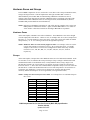
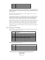
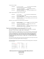
NOTE: Groups are referred to by lowercase letter. For example, there are 9 default Groups in
the CT 610:
Group
0
a
b
c
d
e
f
g
h
i
j
Code Set
0
3
4
11
12
13
14
15
16
off
off
Title
Whole House
Downstairs
Upstairs
Living Room
Dining Room
Kitchen
Patio
Master Bdrm
Master Bath
B&K Components Device Interface Protocol (BKC-DIP) Specification
Version 2.01.00
Updated 01/24/07
Page 17 of 54
k
l
m
n
o
p
q
r
off
off
off
off
off
off
off
off
Code Sets, Zone IDs, and Logical Zones
NOTE: The terms Code Set, Zone ID, and Logical Zone are synonymous.
The terms Code Set, Zone ID, and Logical Zones are synonymous, however various contexts
typically use a specific terminology.
NOTE: Code Sets, Zone IDs, and Logical Zones are referred to by number. For example,
there are 9 default Code Sets / Zone IDs / Logical Zones configured in a CT 610. The
default Code Sets are as follows: 0, 3, 4, 11, 12, 13, 14, 15, and 16.
Code Sets
As in earlier B&K Components devices there are system parameters to allow command and
control of individual Zones (ZA and ZB, previously Z1 and Z2). The term Code Set is primarily
used in conjunction with command and control of a device via RS-232, Infra Red remotes and
keypads. A Code Set is essentially a product ID associated with an IR remote or keypad. A single
Code Set may be assigned to control a single Hardware Zone Group or a Grouping of Zones (see
Groups above). This implies that multiple remotes and keypads may uniquely control the same
Hardware Zone.
NOTE: Code Sets are referred to by number. For example, there are 9 default Code Sets in
the CT 610:
One Whole House Code Set: 0
Two Code Sets assigned to control multiple Hardware Zones: 3 and 4
Six Code Sets assigned to control individual Hardware Zones: 11, 12, 13, 14,
15, and 16
Zone IDs
The term Zone ID is used basically in the same context as a Code Set. However, Zone ID is not
commonly associated with Infra Red remotes and keypads, but thought of as purely a mechanism
to assign Logical Zones to Hardware Zones.
The importance of the term Zone ID has lessened, and it is typically referred to as a Code Set.
Recall, a single Code Set may be assigned to control a single Hardware Zone or a Grouping of
Zones. This implies that multiple remotes may uniquely control the same Hardware Zone.
B&K Components Device Interface Protocol (BKC-DIP) Specification
Version 2.01.00
Updated 01/24/07
Page 18 of 54
NOTE: Zone IDs (Code Sets) are referred to by number. For example, there are 9 default
Zone IDs (Code Sets) in the CT 610:
One Whole House Code Set: 0
Two Code Sets assigned to control multiple Hardware Zones: 3 and 4
Six Code Sets assigned to control individual Hardware Zones: 11, 12, 13, 14,
15, and 16
Logical Zones
Logical Zones are the result of associating Code Sets/Zone IDs to a Group for the control of
Hardware Zones. Whereas Hardware Zones are physical outputs of the device, a Logical Zone is
a higher-level concept, which may encompass multiple Hardware Zones.
Logical Zones are created by Grouping Hardware Zones and assigning a unique Code Set/Zone ID
to this Group. Up to 18 Groups, a – r, are available in the CT 610 and CT 310. It is the careful
setup of the CT 610’s Hardware Zones A-F, linking of Hardware Zones as Groups, and
assignments of Code Sets/Zone Ids that allow Logical Zones to be a very simple and powerful
multi-zone command and control concept. See Groups and Linking Hardware Zone Control
below for more details.
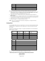
NOTE: Logical Zones are referred to by number, and typically prepended with the letter
“Z” for Zone. For example, there are 9 default Logical Zones in the CT 610:
Z0, Z3, Z4, Z11, Z12, Z13, Z14, Z15, and Z16
NOTE: Logical Zones are given titles and may be referred to by name. For example, there are
9 default Logical Zones in the CT 610 whose names are as follows:
Group 0
Group a
Group b
Group c
Group d
Group e
Group f
Group g
Group h
Group i
Group j
Group k
Group l
Group m
Group n
Group o
Group p
Group q
Group r
Z0
Z3
Z4
Z11
Z12
Z13
Z14
Z15
Z16
Off
Off
Off
Off
Off
Off
Off
Off
Off
Off
Whole House
Downstairs
Upstairs
Living Room
Dining Room
Kitchen
Patio
Master Bdrm
Master Bath
Hardware Zones A, B, C, D, E, F
Hardware Zones A, B, C, D
Hardware Zones E, F
Hardware Zones A
Hardware Zones B
Hardware Zones C
Hardware Zones D
Hardware Zones E
Hardware Zones F
Groups and Linking Hardware Zone Control
B&K Components Device Interface Protocol (BKC-DIP) Specification
Version 2.01.00
Updated 01/24/07
Page 19 of 54
In earlier B&K Components device (Series II products specifically), there were system parameters
to allow Z1 and Z2 power and/or volume controls to be linked.
With the development of the CT 610 (a 6 stereo zone unit, or up to a 12 mono zone unit), the
concept of linking became even more important. In BKC-DIP V2.0x products, such as the CT 610
and CT 310, Logical Zones may be used to link command and control of multiple Hardware
Zones.
Groups allow a means for multiple Hardware Zones to track each other (i.e. if the in volume in one
zone changes, the volume in another zone changes too).
Hardware Zones, A – F, may be linked in up to 18 Groups, a - r. These Groups and their Code
Set/Zone ID assignments determine how many Logical Zones are configured in a system.
NOTE: A Logical Zone is created by assigning a Group a unique Code Set/Zone ID for use
in the control of Hardware Zones. For example, the CT 610’s factory default setting
has 9 logical zones: Z0, Z3, Z4, Z11, Z12, Z13, Z14, Z15, Z16.
An abstract concept such as this requires a concrete example for clarification. The following
example is based upon the factory default Group and Code Set/Zone ID assignments of the
Hardware Zones in the CT 610.
Default CT 610 Example
Using Groups each Hardware Zone of a CT 610 is capable of working with multiple Code
Sets/Zone IDs.
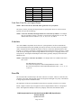
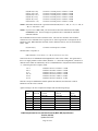
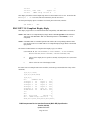
The factory default for each Hardware Zone of the CT 610 is stereo mode. The Group and Code
Set/Zone ID assignments are as follow:
Hardware
Zone
A
B
C
D
E
F
Group
Code Set
(Zone ID)
3 (group a)
3 (group a)
3 (group a)
3 (group a)
4 (group b)
4 (group b)
Group
Code Set
(Zone ID)
11 (group c)
12 (group d)
13 (group e)
14 (group f)
15 (group g)
16 (group h)
Whole House
Code Set
(Zone ID)
0 (group 0)
0 (group 0)
0 (group 0)
0 (group 0)
0 (group 0)
0 (group 0)
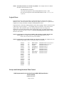
Given the above Group and Code Set/Zone ID configuration yields the following 9 Logical Zones
and their associated Hardware Zone members:
Logical
Zone
Z0
Z3
Z4
Z11
Z12
Hardware Zone members
A, B, C, D, E, and F
A, B, C, D
E and F
A
B
B&K Components Device Interface Protocol (BKC-DIP) Specification
Version 2.01.00
Updated 01/24/07
Page 20 of 54
Z13
Z14
Z15
Z16
C
D
E
F
Viewing the previous Group and Code Set/Zone ID assignments there are 9 Logical Zones: Zone
0 (Whole House), Zone 3, Zone 4 and Zones 11 through Zone 16. Also, note that there is always
an implicit “Whole House” Zone, numbered Zone 0, which combines all Hardware Zones into a
single Logical Zone.
Note, Logical Zone 11 controls Hardware Zone A, however, Hardware Zone A is also part of
Logical Zone 3, and Logical Zone 0.
When referring to Logical Zone 3 in this example, Hardware Zones A, B, C and D are Grouped
(linked) together by a common Code Set. Thus with the above settings, changing the volume in
Logical Zone 3 will change the volume in Hardware Zones (A-D). However, changing the
volume in Logical Zone 13, for example, will only change the volume on Hardware Zone C.
When referring to Logical Zone 4 in this example, Hardware Zones E and F are Grouped (linked)
together via a common Code Set of 4. Thus with the above settings, changing the volume in
Logical Zone 4 will change the volume in Hardware Zones (E and F). However, changing the
volume in Logical Zone 15, for example, will only change the volume on Hardware Zone E.
Changing the volume in Logical Zone 0 changes the volume in all Hardware Zones regardless of
Code Set/Zone ID setup.
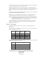
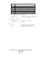
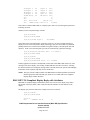
More Complicated CT 610 Example
Let’s take another example with a more complicated Code Set/Zone ID configuration to further
clarify some points regarding Logical Zones:
Hardware
Zone
A.L
A.R
B
C
D.L
D.R
E
F
Group Code Set
(Zone ID)
0 (group 0), 17 (group a), 1 (group d)
0 (group 0), 16 (group b), 12 (group h)
0 (group 0), 16 (group b), 3 (group e), 27 (group i)
0 (group 0), 16 (group b), 3 (group e), 27 (group i)
0 (group 0), 16 (group b), 4 (group f), 27 (group i)
0 (group 0), 16 (group b), 27 (group i), 35 (group g)
0 (group 0), 22 (group c), 35 (group g)
0 (group 0), 22 (group c), 35 (group g)
Given the above Group and Code Set/Zone ID configuration yields the following Logical Zones
and their associated Hardware Zone members:
Logical
Zone
Z0
Z1
Z3
Z4
Hardware Zone members
A.L, A.R, B, C, D.L, D.R, E, and F
A.L
B and C
D.L
B&K Components Device Interface Protocol (BKC-DIP) Specification
Version 2.01.00
Updated 01/24/07
Page 21 of 54
Z12
Z16
Z17
Z22
Z27
Z35
A.R
B, C, and D
A.L and A.R
E and F
B, C, D.L, and D.R
D.R, E, and F
There are several important concepts to note that are illustrated in the above Logical Zones.
1. Logical Zones need not be consecutive. Notice there are no Logical Zones 2, 5-11, 13-15, 1821, 23-26, 28-34, or 36-128. Logical Zones are with created with Groups set to use a valid
Code Sets/Zone ID with any value ranging from 0 (off), 1 to 128.
2. Logical Zones may be created and used to control a single Hardware Zone or Groups of
Hardware Zones.
3. When a Hardware Zone is configured in Mono mode, its left and right halves may be assigned
to various Groups. Such is the case of A.L in Z1, D.L in Z4, A.R in Z12, and in D.R Zone 35.
4. Logical Zone 0, Group 0 always encompasses all Hardware Zones.
5. Notice that Groups j – r are unused (Code Sets set to off).
NOTE: There is no real significance to the choice of Group letter (i.e. Group a has no more
significance that Group r).
SubIdentifiers
Even though BKC-DIP refers only to Logical Zones, it is necessary to obtain information relating
to Hardware Zones. SubIdentifiers are part of BKC-DIP V2.xx syntax that indicates Hardware
Zone settings.
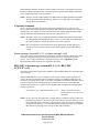
Again, this is best illustrated by example. Let’s again use the default CT 610 Code Set/Zone ID
settings which are as follow:
Hardware
Zone
A
B
C
D
E
F
Logical
Zone
Z0
Z3
Z4
Z11
Z12
Z13
Z14
Z15
Z16
Group Code Set
(Zone ID)
3 (group a)
3 (group a)
3 (group a)
3 (group a)
4 (group b)
4 (group b)
Group Code Set
(Zone ID)
11 (group c)
12 (group d)
13 (group e)
14 (group f)
15 (group g)
16 (group h)
Whole House Code Set
(Zone ID)
0 (group 0)
0 (group 0)
0 (group 0)
0 (group 0)
0 (group 0)
0 (group 0)
Hardware Zone members
A, B, C, D, E, and F
A, B, C, and D
E and F
A
B
C
D
E
F
Now let’s assume the following 6 BKC-DIP Set commands were issued:
B&K Components Device Interface Protocol (BKC-DIP) Specification
Version 2.01.00
Updated 01/24/07
Page 22 of 54
(0,S,PB=FF,1=04;)
(0,S,PC=FF,1=08;)
(0,S,PD=FF,1=0C;)
(0,S,PE=FF,1=10;)
(0,S,PF=FF,1=14;)
(0,S,P10=FF,1=18;)
Set Zone 11 current preset’s volume to –72 dB
Set Zone 12 current preset’s volume to –64 dB
Set Zone 13 current preset’s volume to –56 dB
Set Zone 14 current preset’s volume to –48 dB
Set Zone 15 current preset’s volume to –40 dB
Set Zone 16 current preset’s volume to –32 dB
NOTE: Remember that the Zone is specified in hexadecimal, thus 11 = Bh, 12 = Ch, 13 = Dh, 14
= Eh, 15 = Fh, and 16 = 10h.
NOTE: If you are new to BKC-DIP, you can learn more about Set commands in the S (set)
Command section. For now simply accept that the above commands do what their
comments indicate.
The 6 Hardware Zones now have a different value. The issue now becomes what would be
returned for a Get command sent to Logical Zone 0. Since Logical Zone 0 encompasses all six
Hardware Zones, BKC-DIP must essentially return 6 different answers (one for each Hardware
Zone). Thus:
(0,G,P0=FF,1;)
Get Zone 0 current preset’s volume
Would result in a response of
(0,R,G,P0=FF,1.A=4,1.B=8,1.C=C,1.D=10,1.E=14,1.F=18; cs16)
Notice how the use of SubIdentifiers distinguishes the values of the volume. In Logical Zone 0,
there is as single parameter called volume (identifier “1”), but in this configuration, volume has 6
different values which are indicated by the use of SubIdentifiers in conjunction with the identifier
“1”. Dissecting the above response yields:
1.A=4
1.B=8
1.C=C
1.D=10
1.E=14
1.F=18
Hardware Zone A’s volume is –72 dB
Hardware Zone B’s volume is –64 dB
Hardware Zone C’s volume is –56 dB
Hardware Zone D’s volume is –48 dB
Hardware Zone E’s volume is –40 dB
Hardware Zone F’s volume is –32 dB
Thus the concept of SubIdentifiers further qualifies the identifier, and describes to which
Hardware Zone the value is related.
Again referring to our more complicated example with the following settings:
Hardware
Zone
Group
Zone ID
A
B
C
D
E
F
17
16
16
16
22
22
Left (Mono) Group
Code Set
(Zone ID)
1
3
3
4
35
35
Right (Mono) Group
Code Set
(Zone ID)
12
N/A
N/A
35
N/A
N/A
Whole
House
Zone ID
0
0
0
0
0
0
B&K Components Device Interface Protocol (BKC-DIP) Specification
Version 2.01.00
Updated 01/24/07
Page 23 of 54
Logical
Zone
Z0
Z1
Z3
Z4
Z12
Z16
Z17
Z22
Z35
Hardware Zone members
A.L, A.R, B, C, D.L, D.R, E, and F
A.L
B and C
D.L
A.R
B, C, and D
A.L and A.R
E and F
D.R E, and F
Assume the following Set commands were previously issued:
(0,S,P10=FF,1=18;)
(0,S,P16=FF,1=1A;)
Set Zone 16 (10h) current preset’s volume to –32 dB
Set Zone 22 (16h) current preset’s volume to –28 dB
The following Get command would yield:
(0,G,P23=FF,1;)
Request Zone 35’s (23h) volume
(0,R,G,P23=FF,1.D.R=18,1.E=1A,1.F=1A;cs16)
Where
1.D.R=18
1.E
1.F
Hardware Zone D Right is –32 dB (mono mode)
Hardware Zone E is –28 dB (stereo mode)
Hardware Zone F is –28 dB (stereo mode)
B&K Components Device Interface Protocol (BKC-DIP) Specification
Version 2.01.00
Updated 01/24/07
Page 24 of 54
Host to B&K Device Commands
There are five basic commands that the host can transmit to a B&K Components' device: G, S, D,
M, and X. Each of these, and their format specifiers, are explained in detail below.
G (get) Command
The "G" command is issued by the host to the BKC-DIP device to get information about the
current state of the unit. The BKC-DIP device will respond with an "R" (reply) command
granting the host its desired information (refer to the R (reply) Command section for more about
"R" responses).
There are different types of information the host may inquire about: Presets Settings, System
Settings, Tuner Stations, Zone Specific Settings, Macro Settings, Favorite Settings, Realtime
Status, Display Content, Override Settings, Format Specifications, and Error Log Status. Each of
these is described in detail below.
Presets: (receiveID, G, Pz=nn, identifier, ... identifier; cs16)
Preset information is parameters, which the user can modify on a per preset basis, such as volume,
source, preset title, etc. This information may be "gotten" to archive user presets, or to monitor
the current preset settings (see Pz=FF below).
The preset number, nn, can take on the values 00h to FDh, and FFh. Presets Pz=00 – Pz=FDh are
user presets. Which Logical Zone’s preset is specified by z.
NOTE: Pz=FE is reserved for future expansion.
NOTE: Pz=FF is a special preset. It is the CURRENT PRESET of the unit, which indicates the
CURRENT STATE of the unit.
NOTE: When a user recalls a preset, the recalled preset is copied into the current preset.
Subsequent changes are to this current preset. It is not until the current preset is saved
that these changes are written to a user preset location.
For example:
A user recalls preset 01, which has a V1 volume of –20 dB. The user then
increases the volume to –15 dB. The current preset would reflect that the V1
volume is –15 dB, while preset 01 is still –20 dB.
NOTE: The identifier is a unique hex number assigned to each specific parameter. A complete
list of the preset parameter identifiers for applicable zones are found in the product
specific Appendix A.
NOTE: If no identifiers are specified, the entire preset is returned to the host device.
For example:
(00, G, P1=00; 0258)
(00, G, P2=12; 025C)
returns all data in B&K User Z1 preset 0
returns all data in B&K User Z2 preset 18
See the Presets: (receiveID, S, Pz=nn, identifier = value, ... identifier = value; cs16) section for
more details.
B&K Components Device Interface Protocol (BKC-DIP) Specification
Version 2.01.00
Updated 01/24/07
Page 25 of 54
System Settings: (receiveID, G, S, identifier, ... identifier; cs16)
System settings are parameters which the user may modify, but they are global, or affect the
entire system. Example of these includes power on strings, source input level settings, source
names, etc. Querying system settings is useful for archival purposes.
NOTE: A complete list of the system identifiers is found in product specific Appendix B.
NOTE: If no identifiers are specified, all of the system settings are returned to the host device.
For example:
(00, G, S; 018D) returns all of the B&K unit's system settings
See the System Settings: (receiveID, S, S, identifier=value,...identifier=value; cs16) section for
more details.
Zone Adjustment (Hardware Special) Settings: (receiveID, G, H, identifier, ...
identifier; cs16)
Zone Adjustment (Hardware Special) settings are Zone A to Zone F adjustment parameters which
the user may modify, but they are global, or affect the entire system. Example of these includes
Bass/Treble Gain and Frequency, and Notch Filters. Querying system settings is useful for
archival purposes.
NOTE: A complete list of the system identifiers is found in product specific Appendix R.
NOTE: If no identifiers are specified, all of the system settings are returned to the host device.
For example:
(00, G, H;)
returns all of the B&K unit's zone adjustment (hardware
special) settings
See the Zone Adjustment (Hardware Special) Settings: (receiveID, S, H,
identifier=value,...identifier=value; cs16) section for more details.
Zone Specific Settings: (receiveID, G, Zzz, identifier, ... identifier;cs16)
The zone number, zz, can take on the values 00h to 80h (Zone 0 to Zone 128). If a particular
Logical Zone does not exist in the current device, the command will be ignored and no echo will
be generated.
NOTE: A complete list of zone specific identifiers is found in the product specific Appendix N.
NOTE: If no identifiers are specified, all of the Zone Specific information is returned to the host
device.
For example:
(00, G, Z0;0204)
returns Logical Zone 0’s settings.
See the Zone Specific Settings: (receiveID, S, Zzz, identifier = value, ... identifier = value; cs16)
section for more details.
B&K Components Device Interface Protocol (BKC-DIP) Specification
Version 2.01.00
Updated 01/24/07
Page 26 of 54
Macro Settings: (receiveID, G, Mt=mm, identifier, ... identifier;cs16)
The macro number, mm, can take on the values 00h to FFh (0 to 255) depending on the amount of
memory used by each macro. The macro type, t, specifies which of the various kinds of macros
are being referenced.
NOTE: A complete list of macro identifiers and supported macro types is found in the product
specific Appendix O.
NOTE: If no identifiers are specified, all of the macro information for that particular macro type
is returned to the host device.
For example:
(00, G, M0=20;0296)
returns Serial Macro 32’s settings.
See the Macro Settings: (receiveID, S, Mt, identifier = value, ... identifier = value; cs16) section
for more details.
All Macro Settings: (receiveID, G, Mt, identifier, ... identifier;cs16)
A special form of the Get Macro Settings command deserves discussion. If =mm is omitted,
information for all macros of that type are returned. This is in the form of multiple replies
generated from the single Get.
Given that the device contains 3 macros: 0, 1, 6, and 9 with the messages “added last”, “multiple
”, “macros ”, and “fired ” respectively using the following set commands:
(0,S,M0=1,5="multiple ";066F)
(0,S,M0=6,5="macros ";058D)
(0,S,M0=9,5="fired ";0515)
(0,S,M0=0,5="added last";06A8)
Issuing a Get serial macro (type 0) command without specifing a specific macro number results in
the follow:
(0,G,M0;0187)
(0,E,G,M0,0187;02F4)
Request of all Serial Macros
Echo response
Multiple replys for each macro in the device
(0,R,M0=1,0=0,1=0,2=0,3=2,4=3F,5="multiple ",6=0,7=10,8=1F,9=C4;0EB1)
(0,R,M0=6,0=0,1=0,2=0,3=2,4=3F,5="macros ",6=0,7=E,8=1F,9=C4;0DB3)
(0,R,M0=9,0=0,1=0,2=0,3=2,4=3F,5="fired ",6=0,7=D,8=1F,9=C4;0D3A)
(0,R,M0=0,0=0,1=0,2=0,3=2,4=3F,5="added last",6=0,7=11,8=1F,9=C4;0EEB)
NOTE: The order of the replies is NOT ordered by ascending macro number, but instead by the
order in which the macros were added.
NOTE: Since macros can be sparsely populated (i.e. need not be sequentially numbered 00h –
FEh, and undefined macros do not exist), use of this form of the Get Macro command
indicates which macros are defined in the device.
Tuner Station Settings: (receiveID, G, Tnn, identifier, ... identifier;cs16)
The tuner station number, nn, can take on the values 00h to 13h (stations 1 to 20 respectively).
B&K Components Device Interface Protocol (BKC-DIP) Specification
Version 2.01.00
Updated 01/24/07
Page 27 of 54
NOTE: A complete list of station identifiers is found in the product specific Appendix C.
NOTE: If no identifiers are specified, all of the tuner station information is returned to the host
device.
For example:
(00, G, T01;01BF)
returns Station 2 AM frequency, FM frequency, and FM
Stereo
See the Tuner Station Settings: (receiveID, S, Tnn, identifier = value, ... identifier = value;
cs16) section for more details.
NOTE: In later B&K Component devices, the concept of Tuner Stations was discontinued.
These newer devices do not respond to the Tuner Station specifier. The product specific
Appendix C will indicate whether Tuner Stations are supported or not.
Realtime Status: (receiveID, G, R, identifier, ... identifier; cs16)
Realtime status contains current system information such as Audio Input Presence, Audio Output
Presence, current sample rate, etc.
NOTE: A complete list of Realtime Status information identifiers is found in the product specifc
Appendix D. If Realtime Status messages are not supported by the particular product, it
will also be indicated in that appendix.
NOTE: If no identifiers are specified, all of the realtime status information is returned to the host
device.
KEY NOTE!: Realtime status may be "polled" using the (receiveID, G,R, ...) command,
however the true power of the Realtime status is its ability to generate "interrupts" to the
host unit when the unit senses a Realtime change.
For example, a host program that is to monitor OSD updates (so a "virtual OSD" can be
updated to reflect what the B&K device is displaying) could be written in one of two
ways:
1) Poll the unit continuously at some interval using the (receiveID, G, R, A;
cs16) command comparing the returned value to
the previous value to detect a change in status.
2) Enable the OSD Display Update using (receiveID, S, S, 5A=04; cs16). The
unit will automatically generate a (transmitID,
U,R,A=1;cs16) message only when the OSD has
been updated.
Method 2 does not burden the host with determining if the value changed, does not
require the host to spend time polling, and reduces RS232 bandwidth usage as messages
are generated only on demand.
See the System Parameter for Realtime Enable and Realtime Status message:
(transmitID, U, R, identifier=value;cs16) sections for more details on their usage.
NOTE: Realtime status registers can be read using the (receiveID, G,R, ...; cs16) command
regardless of settings in the Realtime Enable registers.
B&K Components Device Interface Protocol (BKC-DIP) Specification
Version 2.01.00
Updated 01/24/07
Page 28 of 54
Override Settings: (receiveID, G, O, identifier, ... identifier;cs16)
There are particular parameters (which primarily have to do with RS-232 and BKC-DIP settings)
which can be “overridden”, forcing specific values regardless of the corresponding System setting
parameters.
NOTE: A complete list of Override identifiers is found in Appendix P of the appropriate BKCDIP Product Specific Appendices.
NOTE: If no identifiers are specified, all of the Override Setting information is returned to the
host device.
For example:
(00, G, O;0189)
returns all Override settings for receive ID 0 units
See the Override Settings: (receiveID, S, O, identifier=value,...identifier=value; cs16) section
for more details on identifiers.
Display Content: (receiveID, G, D, d;cs16)
This command is used to obtain the ASCII text currently displayed by the unit.
The display device specifier, d, can currently take on the value of F for the front panel display or
O for the On screen display (assuming the B & K Components' device under control supports a
front panel display and/or an On screen display).
For example:
(00, G, D, O; cs16)
requests the current contents of the OSD of units with Receive
IDs of 00h
requests the current contents of the front panel display of units
with Receive IDs of 01h
(01, G, D, F; cs16)
NOTE: See the Reply from the Get Display command (transmitID, G, D, d; cs16) section for
more details on the format of the returned data
Format Specification: (receiveID, G, Ff; cs16)
BKC-DIP is designed to be generic so that as B&K Components devices' features expand,
backwards compatibility can be maintained. For this reason, the internal data structures and
features can be queried to determine which particular B&K Component unit is currently
connected. The currently supported format specifiers, Ff are:
Preset Format:
(00, G, Fz=0; 01B0)
request a comma delimited list of available PRESET
parameter identifiers and their maximum values of
units with Receive IDs of 00h for zone z. See the
product specific Appendix A for a detailed listing.
System Format: (00, G, F1; 01B1)
requests a comma delimited list of available
SYSTEM parameter identifiers and their maximum
values of units with Receive IDs of 00h. See the
product specific Appendix B for a detailed listing.
Tuner Format:
requests a comma delimited list of available TUNER
STATION parameter identifiers and their maximum
values of units with Receive IDs 00h. See the
(00, G, F2; 01B2)
B&K Components Device Interface Protocol (BKC-DIP) Specification
Version 2.01.00
Updated 01/24/07
Page 29 of 54
product specific Appendix C for a detailed listing.
NOTE: B&K Units after Series I (AVR 202, Ref 20, PT 3, etc.) do not support Tuner channels.
If a F2 format request is made of these newer units, they will simply ignore the request.
RealtimeFormat: (00, G, F3; 01B3)
requests a comma delimited list of available
REALTIME STATUS information identifiers and
their maximum values of units with Receive IDs of
00h. See the product specific Appendix D for a
detailed listing.
Unit Specifier:
(00, G, F4; 01B4)
requests a comma delimited list of unit features and
ASCII strings describing the device (name, version)
of units with Receive IDs of 00h. See the product
specific Appendix E for a detailed listing.
Override Format: (00, G, F5; 01B5)
requests a comma delimited list of available
OVERRIDE parameter identifiers and their
maximum values of units with Receive IDs 00h. See
the product specific Appendix P for a detailed
listing.
Error Format:
requests a comma delimited list of available ERROR
LOG parameter identifiers and their maximum values
of units with Receive IDs 00h. See the product
specific Appendix M for a detailed listing.
(00, G, F6; 01B6)
Zone Specific Format: (00, G, Fz=7;cs16)
request a comma delimited list of available ZONE
SPECIFIC parameter identifiers and their maximum
values of units with Receive IDs of 00h for zone z.
See the product specific Appendix N for a detailed
listing.
Macro Format: (00, G, Ft=8;cs16)
request a comma delimited list of available MACRO
parameter identifiers and their maximum values of
units with Receive IDs of 00h for Macro type t. See
the product specific Appendix O for a detailed
listing.
Zone Adjustment Format: (00, G, F9;cs16) requests a comma delimited list of available ZONE
ADJUSTMENT (HARDWARE SPECIAL)
parameter identifiers and their maximum values of
units with Receive IDs of 00h. See the product
specific Appendix R for a detailed listing.
Several examples follow for clarification:
(00, G, F4; 01B4)
(00, E, G, F4, 01B4; 02F8)
get unit format of units with
Receive ID of 00h
echo get command back to host
from unit with a Transmit ID of
0Fh
B&K Components Device Interface Protocol (BKC-DIP) Specification
Version 2.01.00
Updated 01/24/07
Page 30 of 54
(0, R, F4,0= "AVR 202", 1="V2.02"...; cs16)
(00, G, F1=0;)
(00, G, F2=0;)
(00, G, F1;)
(00, G, F2;)
(00, G, F3;)
(00, G, F4;)
(00, G, F5;)
(00, G, F6;)
(00, G, F1=7;)
(00, G, F2=7;)
(00, G, F0=8;)
(00, G, F1=8;)
(00, G, F9;)
reply containing unit (Transmit ID 00h) info
get available Z1 preset parameters and max values
get available Z2 preset parameters and max values
get available system parameters and max values
get available tuner station parameters and max values
get available realtime status info and max values
get available unit format info
get available override parameters and max values
get available error log parameters and max values
get available Z1 zone specific parameters and max values
get available Z2 zone specific parameters and max values
get available Macro Type 0 parameters and max values
get available Macro Type 1 parameters and max values
get available zone adjustment (Hardware Special) and max
values
NOTE: Do not confused F1=0, F2=0, F1=7, F2=7, or F1=8 with F1 and F2. They look
somewhat similar but have very different meanings. F1=0 and F2=0 access available
Preset parameters for Z1 and Z2 respectively. F1=7 and F2=7 access available Zone
Specific parameters for Z1 and Z2 respectively. F1=8 accesses available Macro
parameters for Macro type 1. In contrast, F1 accesses available System parameters and
F2 accesses available Tuner parameters.
Thus, when parsing Format specifiers, the presence of the equal sign, “=”,
significantly alters the meaning of the Format specifier. Specifically, the format is
Fx=fs, where x is some additional specifier (often a Logical Zone number) and fs is
the Format Specifier.
For more information regarding the data returned to the host from the BKC-DIP device, see the E
(echo) Command and R (reply) Command sections.
NOTE: For a complete listing of Format Specifier parameters refer to the appropriate Product
Specific Appendices.
Error Log Status: (receiveID, G, E, identifier, ... identifier; cs16)
The B&K Components’ device constantly monitors its performance. In the unlikely event that a
system error occurs, the B&K Component’s device logs the occurrence and corrects the problem
(if possible). The status of the Error Logs can be queried monitor system performance.
For example:
(0, G, E, 0, 2;0209)
Returns logged count of Preserved State and Non-Volatile
Memory errors from a Series II device.
NOTE: For a complete listing of Error Log parameters and their meanings see the complete
listing in the product specific Appendix M.
Favorite Settings of a Preset: (receiveID, G, A, identifier, ... identifier; cs16)
There are two ways to view favorite presets: from a Zone centric view or from a Preset centric
view. To see which presets are favorite to a particular Zone, query the Zone Specific favorite
preset bitmaps. See Zone Specific Settings: (receiveID, G, Zzz, identifier, ... identifier;cs16)
section of this document for more details.
B&K Components Device Interface Protocol (BKC-DIP) Specification
Version 2.01.00
Updated 01/24/07
Page 31 of 54
The Get fAvorite command, like the Zone Specific favorite preset bitmaps, also indicates favorite
settings, but from a Preset centric point of view. This command indicates in which logical zones a
particular preset is favorite. By contrast, the Zone Specific favorite preset bitmaps indicate which
presets are favorite for a particular zone.
NOTE: The specifier A is used, as the F specifier was already used for Format Specification.
For example, the following depicts querying the Favorite Settings of preset 10h (16 decimal) from
a factory default CT 610 which as Logical Zones 0, 3, 4, 11, 12, 13, 14, 15, and 16:
(0,G,A=10;01E9)
Request Favorite Settings of Preset 10h (16 decimal)
(0,E,G,A=10,01E9;0365)
Echo response
(0,R,A=10,0=0,3=0,4=0,B=0,C=0,D=0,E=0,F=0,10=0;09A1)
Preset 16 is not favorite in Logical Zones 0, 3, 4, 11
(Bh), 12 (Ch), 13 (Dh), 14 (Eh), 15 (Fh), or 16 (10h).
NOTE: If no identifiers are specified, the favorite settings for all zones of the specified preset are
returned to the host device.
As another example, the following is a Get for just zone 4 and 11 of preset 10h.
(0,G,A=10,4,B;02B7)
Request Favorite Settings of Preset 16, Z4 and Z11
(0,E,G,A=10,02B7;0361)
Echo response
(0,R,A=10,4=0,B=0;039C)
Preset 16 is not favorite in Logical Zones 4 or 11
(Bh)
S (set) Command
The "S", set, command is sent by the host to change the state of the B&K Components' device.
This is the counterpart of the "G", get, command (see the G (get) Command section for further
details). The host may set different types of information: Presets, System Settings, Zone Specific
Settings, Macro Settings, Favorite Settings, Tuner Station Settings, Override Settings, and IR and
Front Panel Commands.
Presets: (receiveID, S, Pz=nn, identifier = value, ... identifier = value; cs16)
Presets data can be set using the Pz=nn specifier. Similar to the "G" get command, nn can range
from 00h – FDh, or FFh for the current preset, and z specifies the zone.
NOTE: Pz=FE is reserved for future expansion.
NOTE: Pz=FF is a special preset. It is the CURRENT PRESET of the unit, which indicates the
CURRENT STATE of the unit. When a user recalls a preset, the recalled preset is copied
into the current preset. Subsequent changes are to this current preset. It is not until the
current preset is saved that these changes are written to a user preset location.
The identifier / value portion of the message has the following format:
(00, S, P1=01, 00="Zone 1 Title", 01=60, 03=1, ... ;cs16)
Each parameter is and its respective value are delimited by the ASCII equal sign, "=".
The parameter's identifier is to the left of the equal sign, while the parameter value is to the right
of the equal sign. If the parameter is a string, the parameter value is a string denoted by being
surround in double quotes.
Dissecting the previous example:
B&K Components Device Interface Protocol (BKC-DIP) Specification
Version 2.01.00
Updated 01/24/07
Page 32 of 54
..., 00="Zone 1 Title", ...
00
=
"Zone 1 Title"
..., 01=60, ...
01
=
60
parameter identifier (in this case, the Z1 preset title)
delimits identifier on left, value on right
parameter value (in this case a string)
parameter identifier (in this case, Z1 volume)
delimiter
parameter value (in this case, 60h or 0 dB)
Note that parameter identifier, equal sign, and parameter value are delimited by ",", the ASCII
comma character. All of the parameter identifiers do not need to be specified. This is to allow
only specific parameters to be updated.
For example:
(00, S, P2=0A, 00="New Z2 Title", 01=4D;cs16)
where only the parameter 00 (Z2 preset title) and parameter 01 (Z2 volume) are modified.
NOTE: For a complete listing of preset parameter identifiers and maximum values for applicable
zones see the complete listing in the product specific Appendix A.
System Settings: (receiveID, S, S, identifier=value,...identifier=value; cs16)
Analogous to setting presets, system settings may also be modified.
In the following Reference 30 example, parameter 00 (V1 Input title) and parameter 08 (left
speaker offset level) are modified in units with Receive IDs of 00h.
(00, S, S, 00="VCR1", 08=03; 04F6)
In this example, the V1 Input title has been modified to "VCR1" and the left speaker offset level is
now 03h (or –10.5 dB).
NOTE: For a complete listing of system parameter identifiers and maximum values see the
complete listing in the product specific Appendix B.
Zone Adjustment (Hardware Special) Settings: (receiveID, S, H,
identifier=value,...identifier=value; cs16)
Analogous to setting presets, zone adjustment (hardware special) settings may also be modified.
In the following CT600.3 example, parameter 00 (Zone A Room EQ Bass Gain) and parameter 02
(Zone C Room EQ Bass Gain) are modified in units with Receive IDs of 00h.
(00, S, H, 00=00, 02=01;)
In this example, the Zone A Room EQ Bass Gain is now at -18.0 dB and Zone C Room EQ Bass
Gain is now at -17.5 dB.
NOTE: For a complete listing of zone adjustment (hardware special) parameter identifiers and
maximum values see the complete listing in the product specific Appendix R.
B&K Components Device Interface Protocol (BKC-DIP) Specification
Version 2.01.00
Updated 01/24/07
Page 33 of 54
Zone Specific Settings: (receiveID, S, Zzz, identifier = value, ... identifier = value;
cs16)
Just as there are parameters which are associated with preset (i.e. Preset Parameters), the are other
parameters which are associated with Logical Zones. These parameters are called Zone Specific
settings.
The zone number, zz, can take on the values 00h to 7Fh (Zone 0 to Zone 128). If a particular
Logical Zone does not exist in the current device, the command will be ignored and no echo will
be generated.
In the following CT 610 example, the Zone 7 parameter 0 (Zone title) is modified in units with
Receive IDs of 01h.
(1, S, Z7, 0=”Living Room”;)
NOTE: For a complete listing of zone specific parameter identifiers and maximum values see the
complete listing in the product specific Appendix N.
Macro Settings: (receiveID, S, Mt, identifier = value, ... identifier = value; cs16)
The macro number, mm, can take on the values 00h to FFh (0 to 255) depending on the amount of
memory used by each macro. The macro type, t, specifies which of the various kinds of macros
are being referenced.
In the following CT 610 example, the serial macro (type 0) number 10 is setup for a unit with
Receive ID of 00h:
(0, S, M0=A, 0=1, 1=C4, 5=”(0,S,S,0=\”Laser\”;)”;)
The above command setup serial macro 10 which will be triggered when Zone 1 with an IR
payload of C4h (Volume -) is receive. When triggered, it will transmit the serial payload
(0,S,S,0=”Laser”;)
via the serial port of the B&K Components’ device.
NOTE: A complete list of macro identifiers and supported macro types is found in the product
specific Appendix O.
Serial Macro
The Serial Macro capability allows B&K IR commands to send ASCII serial commands to control
other devices such as lighting controllers, or even other B&K Component devices.
Each serial macro can be of arbitrary length up to the amount of non-volatile memory allocated for
this feature. Refer to Appendix O of the appropriate product specific document for maximum
lengths.
NOTE: For a type 0 macro (serial macro), unspecified identifiers have the default values as
specified in the product specific appendices Appendix O.
Escape Characters in Serial Macros
Since the all BKC-DIP strings are surrounded by double quotes, “ ”, these characters must be
B&K Components Device Interface Protocol (BKC-DIP) Specification
Version 2.01.00
Updated 01/24/07
Page 34 of 54
escaped in order to appear in the serial macro. The escape character is the backslash, \, character.
This also implies that backslashes must be escaped to differentiate its two meanings: escape or the
actual backslash character.
For example, if you wanted a serial macro to emit the string
String in “double quotes”
The syntax to set serial macro 0 with this payload would look like
(0, S, M0=0, 5=”String in \”double quotes\””;)
Notice the addition of the backslash before the double quotes embedded in the string.
Another example demonstrates the use of escape characters for both backslashes and double
quotes in order to emit the string
\backslashed\ and “quoted”
The corresponding set command for serial macro 1 would be
(0, S, M0=1, 5=”\\backslashed\\ and \”quoted\””;)
IR Macro
NOTE: Currently no V2.0 BKC-DIP product has the hardware capable of transmitting IR
macros. This will be a future enhancement.
Tuner Station Settings: (receiveID, S, Tnn, identifier = value, ... identifier = value;
cs16)
Tuner data can be set using the Tnn specifier. Similar to the "G" get command, nn can range from
00h – 13h.
In the following example, parameter 01 (FM frequency) of station 5 is modified in units with
Receive IDs of 02h.
(02, S, T04, 01=20;032C)
In this example, tuner station 5's FM frequency has been set to 20h (93.9 MHz).
NOTE: For a complete listing of tuner station parameter identifiers and maximum values see the
complete listing in the product specific Appendix C.
NOTE: In later B&K Component devices, the concept of Tuner Stations was discontinued.
These newer devices do not respond to the Tuner Station specifier.
Favorite Settings of a Preset: (receiveID, S, A, identifier=value, ...
identifier=value; cs16)
Similar to the two views for getting favorite presets, there are two views for setting favorite
presets: from a Zone centric view or from a Preset centric view. To attribute presets as favorite in
a particular Zone, the Zone Specific favorite preset bitmaps may be set. See the Zone Specific
B&K Components Device Interface Protocol (BKC-DIP) Specification
Version 2.01.00
Updated 01/24/07
Page 35 of 54
Settings: (receiveID, S, Zzz, identifier = value, ... identifier = value; cs16) section of this
document for more details.
The Set favorite command, like the Zone Specific favorite preset bitmaps, can also be used to
attribute favorite settings to zones, but from a Preset centric point of view. This command allows
setting the favorite preset attribute of particular logical zones for a specific preset. By contrast, the
Zone Specific favorite preset bitmaps allow attributing various presets as favorite for a particular
zone.
NOTE: The specifier A is used, as the F specifier was already used for Format Specification.
For example, the following depicts setting the Favorite Settings of preset 10h (16 decimal) in an
otherwise factory default CT 610 which as Logical Zones 0, 3, 4, 11, 12, 13, 14, 15, and 16:
(0,S,A=10,0=1,3=1,4=0;0459)
(0,E,S,A=10,0459;0364)
Attribute Zones 0 and 3 as favorite, and 4 as not for
Preset 10h (16 decimal)
Echo response
(0,G,A=10;01E9)
Get command to verify previous Set example
(0,E,G,A=10,01E9;0365)
Echo response
(0,R,A=10,0=1,3=1,4=0,B=0,C=0,D=0,E=0,F=0,10=0;09A3)
Indicates that Zones 0 and 3 are favorite, and Zones
4, 11 (Bh), 12 (Ch), 13 (Dh), 14 (Eh), 15 (Fh) and 16
(10h) are not attributed as favorite for preset 16 (10h)
Override Settings: (receiveID, S, O, identifier=value,...identifier=value; cs16)
The settings of the various RS-232 and BKC-DIP options are available in the System Settings.
The question arises, “How can the RS-232 and BKC-DIP options of the connected B&K
Components’ device be modified via RS-232 and BKC-DIP?” This dilemma can be addressed
using the Override Settings.
The Override Setting parameters mirror (or shadow) particular key System Setting parameters.
When the Override Settings are activated, by setting the Override Active parameter, the system
ignores various System Settings and uses the corresponding Override Settings instead. An
example will help clarify.
Suppose in a particular application it is required that the user be able to change the System Setting
parameters BKC-DIP Echo Enabled, Front Locked, and IR Locked (for a complete listing of
system parameter identifiers and maximum values see the complete listing in the product specific
Appendix B). However, simultaneously, the RS-232 application requires Echo commands to
verify proper transmission and regulate flow control while the front panel and IR commands
should be locked to assure the device under control does not respond to outside (non RS-232)
stimuli. The following command allow this:
(00, S, O, 0=1, 4=1, 6=1, 7=1, FF=A;04CE)
Dissecting the previous command reveals (see refer to the product specific Appendix P for details
regarding the Override Parameter values):
.. 0=1 ..
.. 4=1 ..
.. 6=1 ..
Override Active is activated
Override Echo Enabled is enabled
Override Front Locked is locked
B&K Components Device Interface Protocol (BKC-DIP) Specification
Version 2.01.00
Updated 01/24/07
Page 36 of 54
.. 7=1 ..
.. FF=A..
Override IR Locked is locked
Activate Override Timeout in 1.0 second
So long as Override Active is activated, the system ignores the System Setting parameters Echo
Enabled, Front Locked, and IR Locked. This allows the user to freely change these System
Settings without interfering with current serial communication parameters. When the user is
finished modifying the device settings, the following command deactivates the Override Settings,
and the device reverts to using the corresponding System Settings:
(00, S, O, 0=0;025E)
Override Active is deactivated, use System Settings
NOTE: The Override Settings revert to their default parameter values after a “cold boot” (i.e.
power cycle) NOT a “warm boot” (i.e. awakening from “Sleep” state). See product
specific Appendix P for a listing of the default parameter values.
NOTE: If the Override Settings changes the baud rate, the Echo response will be transmitted at
the new overridden baud rate.
Override Timeout
One use for the Override Setting Baud Rate can be to negotiate higher baud rates. The issue that
arises is what to do if the Override Baud Rate is not reliable. The following scenario could occur:
The System is communicating at 9600 Baud.
The Override command is issued (at 9600 Baud) to change the Override Baud Rate to
115200 Baud.
For whatever reason (long cable, noisy environment, etc.) the unit cannot communicate at
115200 Baud, however the unit is now in Override mode at 115200 Baud.
RS-232 communication is now lost with the unit with no remedy.
The answer to the above dilemma is the use of the Override Timeout parameter. The Override
Timeout parameter specifies a timeout period in which, if the Override Timeout is not cleared, the
BKC-DIP device will drop out of Override mode. This provides the means for a software
acknowledge of the new Override state and a means of recovering from Override Baud Rate
communication loss. The following is an example of the use of the Override Timeout feature:
(0, S, O, 0=1,1=8, FF=A; cs16)
(0, S, O, FF=0; cs16)
Activate Override 115200 Baud, 1.0 second timeout
(transmitted at the non-override Baud rate)
Clear Override Timeout (transmitted at the new
Override Baud Rate of 115200)
If the previous clearing of the Override Timeout was received within 1.0 seconds
At Override Baud Rate:
(0, G, O, 0; cs16)
Get Override Active state
(0, R, O, 0=1; cs16)
Reply indicates still in override mode
Else Override Timeout occurred because clearing of timeout was not received
At Override Baud Rate:
(0, G, O, 0; cs16)
Get Override Active state
No response from unit
At non-Override Baud Rate:
(0, G, O, 0; cs16)
Get Override Active state
B&K Components Device Interface Protocol (BKC-DIP) Specification
Version 2.01.00
Updated 01/24/07
Page 37 of 54
(0, R, O, 0=0; cs16)
Reply indicates NOT in override mode
NOTE: The use of the Override Timeout is not mandatory, but very strongly recommended
especially when using Override commands to modify Baud Rate.
IR Command: (receiveID, S, I, z=ir; cs16)
(only applicable to units with IR Control capabilities)
The BKC-DIP can be used to send virtual IR commands to the attached B&K Components device.
For example, the Zone 2 IR code for B&K volume down is C4h, thus:
(00, S, I, 2=C4;02A1)
would appear to the device as if the user had issued a Zone 2 Volume down command from the
IR remote to a unit of Receive ID 00h.
NOTE: z of 1 is Zone 1, z of 2 is Zone 2, z of C is Zone 12.
NOTE: For a complete listing of IR commands, see the complete listing in the product specific
Appendix F.
Front Panel Commands: (receiveID, S, F, z=fp; cs16)
(only applicable to units with Front Panel Control capabilities)
The BKC-DIP can be used to send virtual front panel button pushes to the attached B&K
Components device.
For example, the Zone 1 front panel code for volume down is 0Ah, thus:
(01, S, F, 1=0A; 0298)
would appear to the device as if the user had turned the volume down from the front panel of the
Receive ID 01h unit.
NOTE: z of 1 is Zone 1, z of 2 is Zone 2.
NOTE: For a complete listing of front panel commands, see the complete listing in the product
specific Appendix G.
Error Logs: (receiveID, S, E, identifier=value,...identifier=value; cs16)
It is possible to clear the Error Logs via a Set command with a value of 0.
For example:
(0, S, E, 0=0, 2=0; 02EF)
Reset the Preserved State and Non-Volatile Memory
Error logs of a Series II product to zero.
NOTE: It is possible to set the Error Logs to ANY value from 00h – FFh, so it is possible to test
Error response logic via artificially generating non-zero Error Log values. However, the
most typical application would be value of 0 to reset an Error Log.
NOTE: Error Logs are NOT cleared by a factory reset sequence in order to preserve this
important information which B&K Components’ customer service may request if the unit
B&K Components Device Interface Protocol (BKC-DIP) Specification
Version 2.01.00
Updated 01/24/07
Page 38 of 54
requires servicing (however, upgrading to new software WILL automatically clear the
Error Logs). The only way to clear Error Logs the use of this Set command.
NOTE: For a complete listing of Error Log parameters and their meanings see the complete
listing in the product specific Appendix M.
D (display) Command
The BKC-DIP can be used to display ASCII text to either the Front Panel Display (FP), or the On
Screen Display (OSD), or to change the states of the LEDs on the front panel.
NOTE: For a complete list of displayable ASCII characters see the product specific Appendix H.
On Screen Display (O): (receiveID, D, O, Ttt, Mm, Xcc, Yrr, "text", ... Xrr, Ycc,
"text"; cs16)(only applicable to units with On Screen Display capabilities)
B&K Component units featuring On Screen Displays can display text positioned on the On Screen
Display.
Ttt
where tt * 100ms is the timeout before the display is cleared, and T00 indicates
the display should not timeout. Valid tt values are from 00 (no timeout) to FF
(25.5 seconds).
Mm
where m is the video overlay mode
0 is non-overlay mode, text is displayed over background color "blue screen"
1 is overlay mode, text is displayed over video (if video present)
Xcc
where cc is the column where the text is positioned
Yrr
where rr is the row where the text is positioned
The following is an example:
(00, D, O, T64, M0, X02, Y04, "Hello World"; 0974)
where
00
T64
M0
X02
Y04
is the Receive ID, so text will only be displayed on units with receive IDs of 00h
will clear the display after 64h * 100ms (10seconds)
indicates the text will displayed over background color "blue screen"
indicates the displayed text will start at column 02h (the third column)
indicated the displayed text will start at row 04h (the fifth row)
NOTE: T00 indicates text will not timeout.
NOTE: There is only one display timeout per unit in the system. Therefore, timeouts for the
OSD and Front Panel can interact. For example:
(00, D, O, T64, M0, X0, Y0, "10 sec timeout";cs16)
(00, D, F, T32, X0, Y0, "5 sec timeout";cs16)
The text "10 sec timeout" would appear on the OSD and "5 sec timeout" would be
displayed on the Front Panel, however, BOTH displays would be cleared in 5 seconds
when the Front Panel timed out.
The last timer value supercedes any previous timer values. For example, a variation on
the previous example:
B&K Components Device Interface Protocol (BKC-DIP) Specification
Version 2.01.00
Updated 01/24/07
Page 39 of 54
(00, D, F, T32, X0, Y0, "5 sec timeout";cs16)
(00, D, O, T64, M0, X0, Y0, "10 sec timeout";cs16)
would clear BOTH displays after 10 seconds when the OSD timed out.
NOTE: Text cannot be displayed when zone 1 is off.
NOTE: The X and Y coordinates are zero based, with x00, y00 being in the upper left corner of
the display (see exception below for Overlay Mode and 16:9 Aspect Ratio).
NOTE: Currently the On Screen dimensions are 28 characters by 11 characters. Valid OSD
coordinates are 00h to 1Bh by 00h to 0Ah (see exception below for Overlay Mode and
16:9 Aspect Ratio).
NOTE: Important Notes when using Overlay Mode with System Setting Monitor Aspect
Ratio of 16:9:
NOTE: When Monitor Aspect Ratio is set to 16:9, the OSD rows 0 and 3 are not
displayed when in Overlay mode. This implies that when the Monitor Aspect
Ratio is set to 16:9 and an OSD Overlay message is displayed, effectively x04,
y00 is the upper left corner and that valid (visible) coordinates are 00h to 1Bh by
04h to 0Ah.
NOTE: Some older versions of code permit writing to rows 02h and 03h while in
Overlay mode. This practice is highly discouraged for compatibility issues, and
as it may interfere with some monitors’ proper display of 16:9 ratio material (i.e.
writing to rows 02h – 03h may force the monitor back to 4:3 ratio temporarily).
NOTE: Non-overlay mode always uses the full OSD resolution, and thus valid OSD
coordinates for Non-overlay mode are always 00h to 1Bh by 00h to 0Ah (X
columns and Y rows respectively) regardless of the Monitor Aspect Ratio
setting in System parameters.
NOTE: The display is blanked with each D (display) command.
To display a multi-line message, use the following form:
(00, D, O, T00, M0, X04, Y01, "Multiple", X05, Y02, "Lines of", X06, Y4,
"Text";1181)
NOTE: The B&K Component's device has priority over its OSD. Thus, system events can
overwrite BKC-DIP displayed text. For example:
(00, D, O, T00, M0, X0, Y0, "No Timeout", X0, Y1, "But System can overwrite";13AF)
The text will appear on the On Screen Display. If, however, the unit must display
information (such as when the user changes volume), the OSD will be overwritten (in this
case with the volume information).
Front Panel Display (F): (receiveID, D, F, Ttt, Xcc, Yrr,"text";cs16)
(only applicable to units with Front Panel Display capabilities)
B&K Components Device Interface Protocol (BKC-DIP) Specification
Version 2.01.00
Updated 01/24/07
Page 40 of 54
Ttt
Xcc
Yrr
where tt * 100ms is the timeout before the display is cleared, and T00 indicates
the display should not timeout. Valid tt values are from 00 (no timeout) to FF
(25.5 seconds).
where cc is the column where the text is positioned
where cc is the row where the text is positioned
Text may be displayed and positioned on the Front Panel Display using the following display
message:
(0, d, f, t0, x0, y2, "Testing";0756)
where
0
t0
x0
y2
receive ID, text will only be displayed on the Front Panels of units with receive
IDs of 00h
indicates the display will NOT be clear by a timeout
indicates the displayed text will start at row 00h (the first row)
indicated the displayed text will start at column 02h (the third column)
NOTE: T00 indicates text will not timeout.
NOTE: The X and Y coordinates are zero based. Currently, the Front Panel Display dimensions
are 16 characters by 1 character.
NOTE: Valid screen FP coordinates are 00h to 0Fh by 00h.
NOTE: The B&K Component's device has priority over its Front Panel Display. Thus, system
events can overwrite BKC-DIP displayed text. For example:
(0, D, F, T00, X0, Y0, "No Timeout";07CA)
The text will appear on the Front Panel Display. If, however, the user then changes the volume,
the FP will be overwritten with the volume information.
LED display: (receiveID, D, L, Ttt, n=bitmap; cs16)
B&K Component units' front panel LEDs may be individually controlled.
Ttt
where tt * 100ms is the timeout before the display is cleared, and T00 indicates
the display should not timeout. Valid tt values are from 00 (no timeout) to FF
(25.5 seconds).
n
indicates which LED buffer
bitmap indicates which of the LEDs are active (1 = active, 0 = inactive)
NOTE: T00 indicates LEDs will not timeout.
For example, to activate the DOWN LED and the REAR LEVEL LED, send the following
command:
(00, D, L, T00, 1=21; 0360)
1
21h
LED Buffer 1
01h (the DOWN LED) + 20h (the REAR LEVEL LED)
NOTE: Due to the front panel electronics, only one of each of the following electrical banks of
B&K Components Device Interface Protocol (BKC-DIP) Specification
Version 2.01.00
Updated 01/24/07
Page 41 of 54
LEDs should be active at a time:
Electrical Bank A
UP, LEVEL, MODE, SOURCE, PRESET, SLEEP, ENTER, MENU, DOWN
Electrical Bank B
CENTER LEVEL, SUB LEVEL, GROUP LEVEL, REAR LEVEL, ZONE 2
Therefore:
(00, D, L, T00, 0=48;cs16)
Invalid, both PRESET and ENTER cannot
be active
(00, D, L, T00, 0=04;cs16)
Valid, only MODE active
(00, D, L, T32, 0=02, 1=01;cs16)
Invalid, both LEVEL and DOWN cannot be
active. Different LED buffers, but the same
electrical bank
(00, D, L, T64, 1=41;cs16)
Valid, DOWN and ZONE 2 are in different
electrical banks, but the same LED buffer
NOTE: For a complete listing of the LED mapping, see the product specific Appendix K.
X (executive) Command
The "X", eXecutive, commands are sent by the host to access various high level functions directly.
As the number of supported eXecutive commands varies per product, please see the product
specific Appendix L for details. In general, some or all of the following eXecutive commands
may be supported:
Recall Preset Command: (receiveID, X, 0, z=nn; cs16)
Save Preset Command: (receiveID, X, 1, z=nn, autoNameMode; cs16)
Power State Command: (receiveID, X, 2, z=onOff; cs16)
Noise Generator State Command: (receiveID, X, 3, state; cs16)
Noise Steering Command: (receiveID, X, 4, speakerIndex=onOff, ... speakerIndex=onOff; cs16)
Noise Increment Command: (receiveID, X, 5; cs16)
Cold Boot Command: (receiveID, X, 6; cs16)
Factory Reset Command: (receiveID, X, 7; cs16)
WARNING!:
Issuing a Factory Reset Command will destroy all user modified
data in the unit (preset, system settings, etc.).
Reinitialize BKC-DIP State Command: (receiveID, X, 8; cs16)
Test Tone State Command: (receiveID, X, 9, level; cs16)
Mute State Command: (receiveID, X, A, z=muteState; cs16)
B&K Components Device Interface Protocol (BKC-DIP) Specification
Version 2.01.00
Updated 01/24/07
Page 42 of 54
M (Macro Trigger) Command: (receiveID, M, t=mm, … ,t=mm;cs16)
As its name implies, the “M”, Macro Trigger, Command is used to trigger macros in the device
via BKC-DIP. This allows BKC-DIP to manually fire a macro in addition to the matching of the
Trigger ID and Trigger Code from a B&K Components IR remote.
The Macro type is t, and mm is the macro number ranging from 00h – FEh.
NOTE: Currently the only supported macro type is 0, Serial Macro.
Assuming the payloads of Macro 1, 6, and 9 are “multiple ”, “macros ”, and “fired.” Respectively,
the following example would result in:
(0,M,0=1,0=6,0=9;)
multiple macros fired
(0,E,M,0=9,034F;0330)
Command to trigger serial macros 1,6, and 9
Output of macros
Echo response of trigger
NOTE: When triggering multiple macros in a single command, the order in which the macros are
triggered is based upon the order they are in the command.
(0,M,0=9,0=1,0=6;)
fired multiple macros
(0,E,M,0=6,034F;032D)
Command to trigger serial macros 9, 1, and 6
Output of macros (note the order)
Echo response of trigger
B&K Components Device Interface Protocol (BKC-DIP) Specification
Version 2.01.00
Updated 01/24/07
Page 43 of 54
B&K Device to Host Commands
There are three basic commands that the B&K Components device can transmit to the host: E, R,
and U. Each of these, and their format specifiers, are explained in detail below.
E (echo) Command
The "E", echo, command provides feedback to the host if the developer would like a closed loop
system. The "E" command simply echoes back the previously received command, format
specifier, and calculated checksum. The host can then compare this information to its transmitted
message to confirm the correct message was received. If an error occurred, the host can choose to
retransmit the message.
For example:
(from host)
(from unit)
(from unit)
(01, G, P1=00; 0259)
"G" get Z1 preset 00 command
from host from a unit with receive ID of 01h
(2, E, G, P1=00, 0259;0397)
"E" a unit with a Transmit ID of
02h echoed get Z1 preset 00 command
(2, R, P1=00, 0=...;cs16)
"R" reply containing preset info
from same unit with Transmit ID of 02h
The echo command contains only the previously received command, format specifier, and
checksum which are echoed with a newly calculated checksum:
(from host)
(from unit)
(00, S, P2=01, 0="Z2 Title", 1=4;06BF)
"S" set Z2 preset 01
command to unit with receive ID of 00h
(1, E, S, P2=01, 06BF; 03C2)
"E" echoed set command
by unit with Transmit ID of 01h, no parameter data
NOTE: The echo command is sent after the unit has processed the message. Since certain
operations take some time to complete (such as saving presets), the echo command can
serve as an indicator that the B & K Components' device has complete the most recent
task.
NOTE: The echo feature may be disabled via the RS-232 PORT SETUP menu screen (under the
ADVANCED SYSTEM SETUP menu).
Implementing Software Flow Control using Echo Commands
Since the echo command is sent after the unit has processed the message, it is an effective way to
implement software flow control protocol (since the hardware does not currently support hardware
flow control).
To implement such a scheme, subsequent messages destined for the device can be “stalled” until
the echo from the previous command is received. In doing so, the developer is assured that the
B&K Components’ device has emptied its receive buffer.
NOTE: If the message “RS232 RX OVRFLOW” appears in the vacu-fluorescent display, it
indicates that the device’s receiver buffer has overflowed, and the previously described
software flow control should be implemented.
R (reply) Command
The "R", reply, command is sent by the device to the host to return information from a "G", get,
host command.
B&K Components Device Interface Protocol (BKC-DIP) Specification
Version 2.01.00
Updated 01/24/07
Page 44 of 54
Using the above example:
(from host)
(from unit)
(from unit)
(01, G, P1=0, 1;0286)
"G" get Z1 preset 00 command
from host destined for units with 01h receive IDs
(1, E, G, P1=0, 0286;0366)
"E" echoed get Z1 preset 00
command from unit with 01h Transmit ID
(1, R, P1=0, 1=47;0309)
"R" reply containing preset info
from unit with 01h Transmit ID
Another example would be in reply to a host get system:
(from host)
(from unit)
(from unit)
(00, G, S;018D)
"G" get system info command from host
from units with 00h receive IDs
(2, E, G, S,018D; 02D9) "E" echoed get system info command from
unit with 02h Transmit ID
(2, R, S, 0=...;cs16)
"R" reply containing system info from same
unit with 02h Transmit ID
Replies also occur in response to get format requests from the host:
(from host)
(from unit)
(from unit)
(00, G, F1=0;021E)
"G" get Z1 preset format command
from host from units with 00h receive IDs
(1, E, G, F1=0,021E ,0364)
"E" echoed get preset format
command from unit with 01h Transmit ID
(1, R, F1=0, 0=”D”...;cs16)
"R" reply containing system preset
info from the same unit with 01h Transmit ID
Reply from the Get Display command (transmitID, G, D, d; cs16)
New to V2.0 BKC-DIP, there are now three different reply types: BKC-DIP V1.0 compliant,
BKC-DIP V2.0 with no attributes, and BKC-DIP V2.0 with attributes.
With the development of V2.0 BKC-DIP, there were two goals with regards to Get Display Reply
messages: minimize data transmitted and address the shortcommings of indicating the attributes
of the text from BKC-DIP V1.0. These design requirements are diametrically opposed, thus 2
reply modes are available in BKC-DIP V2.0 to address these differing goals: BKC-DIP V2.0
Compliant Display Reply without Attributes and BKC-DIP V2.0 Compliant Display Reply
with Attributes.
The reply format of each of these reply types will be discussed below, as well as pros/cons of each
type, plus the system settings required to enable each reply type.
The following documentation will assume the following On Screen Display buffer (currently Bh x
1Ch in size) content:
row
row
row
row
row
row
row
row
0="
CONTROL OUT B
1="Input 1
On
Input 2
2="Input 3
On
Input 4
3="Input 5
On
Input 6
4="Input 7
On
Input 8
5="Input 9
On
Zone In
6="FM Tuner On
AM Tuner
7="
"
On"
On"
On"
On"
On"
On"
"
B&K Components Device Interface Protocol (BKC-DIP) Specification
Version 2.01.00
Updated 01/24/07
Page 45 of 54
row 8="
"
row 9="^_ next item
adjust <>"
row A="
MENU setup control B
"
This display is from the Selected Input setup menu of Control Out B of a CT 610. Notice that the
text “Input 1 On” is selected, which is indicated by the red color above.
The front panel display depicts a rendition of selected portion the menu, which is:
“CB INPUT 1
ON”
BKC-DIP V1.0 Compliant Display Reply
This display reply format is to maintain backwards compatibility with BKC-DIP V1.0 interfaces.
NOTE: BKC-DIP V1.0 Compliant Display Reply Mode is forced regardless of the OSD and
VFD reply mode if the BKC-DIP V2.0 Enabled parameter is not enabled (i.e. V1.0
compliant).
NOTE: If the BKC-DIP V2.0 Enabled parameter is enabled, the corresponding OSD and VFD
reply modes must be set to BKC-DIP V1.0 Compliant Display Reply Mode to obtain this
reply format.
The format of a BKC-DIP V1.0 Compliant Get Display reply is as follows:
(transmitID, R, D, d, 0="row 0 contents", 1="row 1 contents", ... n="row n contents",
80=row 0 selection, 81=row 1 selection, ... 8n=row n selection; cs16)
d
where d is the display device specifier (currently F (front panel) or O (On Screen
Display.
n
where n is the last row of the display's buffer.
the return from our example OSD screen would be (with carriage returns added for clarity in this
document):
(0,G,D,O; 01C9)
(0,E,G,D,01C9;02C8)
(0,R,D,O,
0="
CONTROL OUT B
",
1="Input 1
On
Input 2
On",
2="Input 3
On
Input 4
On",
3="Input 5
On
Input 6
On",
4="Input 7
On
Input 8
On",
5="Input 9
On
Zone In
On",
6="FM Tuner On
AM Tuner On",
7="
",
8="
",
9="^_ next item
adjust <>",
A="
MENU setup control B
",
80=0,81=1,82=0,83=0,84=0,85=0,86=0,
B&K Components Device Interface Protocol (BKC-DIP) Specification
Version 2.01.00
Updated 01/24/07
Page 46 of 54
87=0,88=0,89=0,8A=0;6168)
The above example indicates the primary shortcomming with the BKC-DIP V1.0 Display Reply
format, mainly that it assumed entire lines were selected at a time. This is indicated by the 81=1
in the latter portion of the reply. As a historical note, this assumption was true in Series I and PT 3
B&K devices, but not Series II and forward.
Using the same example for the Front Panel display reply:
(0,G,D,F;)
(0,E,G,D,01C0;02BF)
(0,R,D,F,0="CB Input 1
On
",80=1;09ED)
NOTE: Selection is depicted by another video color (used primarily by the OSD in menus).
The selection index is offset by 80h, therefore the selection index is (row – 80h). If the
row is selected, the value will be 1 otherwise the value will be 0.
For example:
... 81=0,82=1, ... indicates row 1is not selected, row 2 is selected
NOTE: The front panel display buffer is actually 20h x 1h. Thus the reason for the 10h extra
"whitespace" characters in the previous example. This is due to the hardware of front
panel display and how it handles decimal points. Decimal points do not occupy a
character cell by themselves, but rather are associated with the previous character. Thus
worse case, the return buffer could be 2h x 10h (32 (decimal) characters).
For example, assume the following front panel buffer:
Row 0 "0.1.2.3.4.5.6.7.8.9.A.B.C.D.E.F."
th
th
This would fit in the front panel display because the 0 decimal point shares the 0
st
st
character cell, the 1 decimal point shares the 1 character cell, etc. In this case, 20h
characters are displayed in 10h locations. So the reply stream would look like:
(0, R, D, F, 0="0.1.2.3.4.5.6.7.8.9.A.B.C.D.E.F."; cs16)
NOTE: See the product specific Appendix I for special characters returned from the Front Panel
(FP) and On Screen Display (OSD).
BKC-DIP V2.0 Compliant Display Reply without Attributes
BKC-DIP V2.0 Display Replys without attributes contain less information than its V1.0
counterpart, because no attempt is made to try to indicate attributes about the displayed text, only
the raw text itself.
The display reply from the OSD of the example menu screen results in:
(0,G,D,O; 01C9)
(0,E,G,D,01C9;02C8)
(0,R,D,O,
0="
CONTROL OUT B
1="Input 1
On
Input 2
",
On",
B&K Components Device Interface Protocol (BKC-DIP) Specification
Version 2.01.00
Updated 01/24/07
Page 47 of 54
2="Input 3
On
Input 4
3="Input 5
On
Input 6
4="Input 7
On
Input 8
5="Input 9
On
Zone In
6="FM Tuner On
AM Tuner
7="
8="
9="^_ next item
adjust
A="
MENU setup control B
On",
On",
On",
On",
On",
",
",
<>",
";561E)
Notice that in contrast to BKC-DIP V1.0 display replies, there are no 80 through 8A parameters
indicating selection.
Similarly for the front panel display contents:
(0,G,D,F;01C0)
(0,E,G,D,01C0;02BF)
(0,R,D,F,0="CB Input 1
On";06EB)
Notice that for the front panel display (sometimes referred to as VFD (Vacuum-Fluorescent
Display) because of the front panel’s display technology) reply does not include any additional
padding characters to account for the hardware being able to display a decimal point with each
character. In the event a decimal point is present, the returned string expands accordingly.
(0,D,F,T0,X0,Y0,"Decimal Pnts. 1.2.";0957)
(0,E,D,F,0957;02BF)
(0,G,D,F;01C0)
(0,E,G,D,01C0;02BF)
(0,R,D,F,0="Decimal Pnts. 1.2. ";0849)
In many applications selection is unimportant (such as those where BKC-DIP exclusively writes
messages to the unit’s display, since writing via BKC-DIP does not allow selection). Selecting
this format will decrease Get Display message traffic, and will increase the speed at which Display
information can be captured (especially at lower baud rates).
NOTE: This reply format is only available if the BKC-DIP V2.0 Enabled parameter is enabled
and the appropriate OSD and VFD reply modes are set to BKC-DIP V2.0 Compliant
Display Reply without Attributes.
BKC-DIP V2.0 Compliant Display Reply with Attributes
BKC-DIP V2.0 Display Replys with attributes is the most verbose of the display reply modes.
The benefit of this reply mode is that it fully describes the attributes of each character of the
display.
The display reply from the OSD of the example menu screen results in:
(0,G,D,O;01C9)
(0,E,G,D,01C9;02C8)
0,R,D,O,
0="
CONTROL OUT B
",
B&K Components Device Interface Protocol (BKC-DIP) Specification
Version 2.01.00
Updated 01/24/07
Page 48 of 54
1="Input 1
On
Input 2
2="Input 3
On
Input 4
3="Input 5
On
Input 6
4="Input 7
On
Input 8
5="Input 9
On
Zone In
6="FM Tuner On
AM Tuner
7="
8="
9="^_ next item
adjust
A="
MENU setup control B
On",
On",
On",
On",
On",
On",
",
",
<>",
",
80="0,0,0,0,0,0,0,0,0,0,0,0,0,0,0,0,0,0,0,0,0,0,0,0,0,0,0,0",
81="1,1,1,1,1,1,1,1,1,1,1,1,0,0,0,0,0,0,0,0,0,0,0,0,0,0,0,0",
82="0,0,0,0,0,0,0,0,0,0,0,0,0,0,0,0,0,0,0,0,0,0,0,0,0,0,0,0",
83="0,0,0,0,0,0,0,0,0,0,0,0,0,0,0,0,0,0,0,0,0,0,0,0,0,0,0,0",
84="0,0,0,0,0,0,0,0,0,0,0,0,0,0,0,0,0,0,0,0,0,0,0,0,0,0,0,0",
85="0,0,0,0,0,0,0,0,0,0,0,0,0,0,0,0,0,0,0,0,0,0,0,0,0,0,0,0",
86="0,0,0,0,0,0,0,0,0,0,0,0,0,0,0,0,0,0,0,0,0,0,0,0,0,0,0,0",
87="0,0,0,0,0,0,0,0,0,0,0,0,0,0,0,0,0,0,0,0,0,0,0,0,0,0,0,0",
88="0,0,0,0,0,0,0,0,0,0,0,0,0,0,0,0,0,0,0,0,0,0,0,0,0,0,0,0",
89="0,0,0,0,0,0,0,0,0,0,0,0,0,0,0,0,0,0,0,0,0,0,0,0,0,0,0,0",
8A="0,0,0,0,0,0,0,0,0,0,0,0,0,0,0,0,0,0,0,0,0,0,0,0,0,0,0,0"
;CF1B)
Notice that similar to BKC-DIP V1.0 display replies, there are 80 through 8A parameters,
however, the V2.0 attributes are per character. Notice that row 1 attributes (identifier 81h above)
indicates that the first 12 characters have an attribute of 1. This indicates that these characters are
selected.
NOTE: The attribute characters are bitmaps with the following meaning:
Bit 0 = Selected
Bit 1 = Flashing
Currently, the Flashing is not used. Thus the only possible character attribute values are:
0
Bit 1 = 0, Bit 0 = 0
Not Flashing, Not Selected
1
Bit 1 = 0, Bit 0 = 1
Not Flashing, Selected
In the future, the Flashing attribute may also be used, which would also add the following
attribute values:
2
Bit 1 = 1, Bit 0 = 0
Flashing, Not Selected
3
Bit 1 = 1, Bit 0 = 1
Flashing, Selected
Similarly for the front panel display contents:
(0,G,D,F;01C0)
(0,E,G,D,01C0;02BF)
(0,R,D,F,0="CB Input 1
On",
80="1,1,1,1,1,1,1,1,1,1,1,1,1,1,1,1,1,1,1,1,1,1,1,1,1,1,1,1,1,1,1,1"
;1374)
NOTE: Since the entire contents of the front panel display (VFD) are always selected, BKC-DIP
V2.0 Compliant Display Reply with Attributes mode is of questionable use, but is
included for symetry with the OSD and to account for future changes in display
technology.
In some applications, displaying all of the characters’ attributes may be important. This reply
mode overcomes the shortcommings of BKC-DIP V1.0 selection scheme, plus is extensible
B&K Components Device Interface Protocol (BKC-DIP) Specification
Version 2.01.00
Updated 01/24/07
Page 49 of 54
should additional character attributes become available in the future. Selecting this format will
increase Get Display message traffic, and will decrease the speed at which Display information
can be captured (especially at lower baud rates).
NOTE: This reply format is only available if the BKC-DIP V2.0 Enabled parameter is enabled
and the appropriate OSD and VFD reply modes are set to BKC-DIP V2.0 Compliant
Display Reply with Attributes
U (update) Command
The "U", update, command is generated by the device to inform the host of various events.
These events include: Status messages (including the BKC-DIP Active message), the reception of
an IR message, the reception of a front panel button message, and the change in realtime status
(such as detection of various bitstreams, audio present, video present, etc.).
NOTE: The update feature may be disabled via the RS-232 PORT SETUP menu screen (under
the ADVANCED SYSTEM SETUP menu). This is recommended for low baud rates, as
the Update command overhead can make the system less responsive.
NOTE: Due to its importance in the initialization of host applications, the BKC-DIP Active
message (see below for more details) is transmitted regardless of the Update Enable
setting.
Status message: (transmitID, U, S, n=“status message”;cs16)
As the name implies, Status messages are generated by the unit to indicate a change in the status
of the unit. The number and types of Status messages each device can generate is product
specific. For a complete detailed list of the Status messages, refer to Appendix Q of the
appropriate BKC-DIP Product Specific Appendices document.
BKC-DIP Active message: (transmitID, U, S, 0=“BKC-DIP
ACTIVE”;cs16)
One Status message that is supported by all B&K Component BKC-DIP devices is the BKC-DIP
Active message.
When the BKC-DIP device exits a Cold Boot power sequence (either from the application of
power to the unit from the Power On/Off switch, the issuing of a Cold Boot Command, or the
occurrence of a Factory Reset (either via eXecutive Command or Front Panel command)), there is
a period of time before the communication port is initialized and ready to receive BKC-DIP
command. When the device is capable of receiving BKC-DIP commands, the following update
message is generated:
(transmitID, U, S, 0=“BKC-DIP ACTIVE”;cs16)
where transmitID is the unit's
Transmit ID and cs16 is the 16 bit
checksum.
NOTE: In cases where the host application is running during a Cold Boot sequence (either from
the application of power to the unit from the Power On/Off switch, the issuing of a Cold
Boot Command, or the occurrence of a Factory Reset (either via eXecutive Command or
Front Panel command)), it is recommended that the host application poll for the Update
BKC-DIP Active Message before issuing any BKC-DIP commands.
B&K Components Device Interface Protocol (BKC-DIP) Specification
Version 2.01.00
Updated 01/24/07
Page 50 of 54
IR message: (transmitID, U, I, z=ir;cs16)
When the BKC-DIP device receives an IR message, the following message is generated:
(transmitID, U, I, z=ir;cs16)
where transmitID is the unit's Transmit ID, ir is the
received IR command, z is the zone number, and cs16
is the 16 bit checksum.
For example:
(0, U, I,1=C4; 0261)
"U" update to host indicating a Zone 1 <Volume ->
key, C4h, received from unit with Transmit ID of 00h
NOTE: For a complete listing of IR commands, see the complete listing in the product specific
Appendix F.
Front Panel message: (transmitID, U, F, z=ir;cs16)
When the BKC-DIP device receives a front panel message, the following message is generated:
(transmitID, U, F, z=fp;cs16)
where transmitID is the unit's Transmit ID, fp is the
received front panel, z is the zone number, and cs16
is the 16 bit checksum
For example:
(1, U, F, 1=A; 023A)
"U" update to host indicating Zone 1 front panel <Volume -> ,
0Ah, received from unit with Transmit ID of 01h
NOTE: For a complete listing of front panel commands, see the complete listing in the product
specific Appendix G.
Realtime Status message: (transmitID, U, R, identifier=value;cs16)
When an enabled realtime event occurs in the BKC-DIP device, the following message is
generated:
(transmitID, U, R, identifier=value;cs16)
where transmitID is the unit's Transmit ID,
identifier is the identifier as specified in Appendix D,
value its the value, and cs16 is the 16 bit checksum.
NOTE: For a complete listing of Realtime Status identifiers, see the complete listing in the
product specific Appendix D.
NOTE: The Realtime Enable registers are initialized to all DISABLED on power-up. Therefore,
the events that are to generate Update messages must be ENABLED via the Set
command and the Realtime Enable n register specifiers (see the product specific
Appendix B).
For example, to have the B&K device generate an Update message every time the
Sample Rate changes and OSD Display Update occurs:
(00, S, S, 59=20, 5A=04;cs16)
Set bit 5 of Realtime Enable 0 register
Set bit 2 of Realtime Enable 1 register
(enabling Sample Rate and OSD Display
Update respectively on receive ID 00h units)
(1, U, R, 5=sample rate;cs16)
Update from sample rate change from 01h
B&K Components Device Interface Protocol (BKC-DIP) Specification
Version 2.01.00
Updated 01/24/07
Page 51 of 54
(1, U, R, A=1;cs16)
Transmit ID unit
Update indicating OSD update from 01h
Transmit ID unit
NOTE: Realtime status registers can be read using the (receiveID, G,R, ...; cs16) command
regardless of settings in the Realtime Enable registers.
B&K Components Device Interface Protocol (BKC-DIP) Specification
Version 2.01.00
Updated 01/24/07
Page 52 of 54
Use of Receive and Transmit IDs
The primary use of the BKC-DIP Receive and Transmit IDs is to differentiate multiple units on a
common serial bus.
NOTE: The terms "receive" and "transmit" are relative to B&K Components device's
perspective. Host to unit commands (such as G, S, and D) are received by the B&K unit
and therefore contain the Receive ID. Conversely, data from the B&K unit to the host
are transmitted by the unit and therefore contain the Transmit ID of the unit.
The Receive ID
The first token of a host to B&K unit command is the Receive ID. The purpose of the Receive ID
is to allow commands to be sent to a specific unit on a common serial bus with multiple units. The
Receive ID is 00h by default. The Receive ID can be changed to any of 128 settings (00h – 7Fh)
on the RS-232 PORT SETUP menu.
NOTE: It is conceivable of a setup where multiple units could have the same Receive ID. This is
the case if it is desirable to have multiple units respond to the same commands. See the
Multiple Unit Example below for a detailed example.
The Transmit ID
The first token of a B&K unit to host command is the Transmit ID. The purpose of the Transmit
ID is to determine which unit generated a message a common serial bus with multiple units. The
Transmit ID is 00h by default. The Transmit ID can be changed to any of 128 settings (00h – 7Fh)
on the RS-232 PORT SETUP menu.
NOTE: Unlike the Receive ID, each should have a unique Transmit ID, otherwise it is impossible
to determine the source unit of a generated message. See the Multiple Unit Example
below for a detailed example.
A Multiple Unit Example
The following is an example of four B&K Components units (denoted as UNIT0, UNIT1, UNIT2
and UNIT3) on a common serial bus with the following settings:
Unit
UNIT0
UNIT1
UNIT2
UNIT3
Receive ID
00h
01h
00h
02h
Transmit ID
00h
01h
02h
03h
In this example, Host to B&K unit commands are sent to 3 different groups of units: UNIT0 and
UNIT2, UNIT1, and UNIT3. It is very important to note that UNIT0 and UNIT2 both respond to
the same commands from the host because they have the same Receive IDs. It is also important to
note that each unit has a unique Transmit ID (even UNIT0 and UNIT2).
The following example commands (and comments) should help clarify:
th
(01, G, S, 00;)
(1, E, G, S, received cs16;cs16)
(1, R, S, 0="V1 ";cs16)
request of UNIT1's V1 Title (0 system parameter)
echo confirming reception of command by UNIT1
UNIT1 replies with its V1 Title
(02, G, P1=FF, 1;)
(3, E, G, P1=FF, received cs16; cs16)
request of UNIT3's Z1 current preset Volume
echo confirming reception of command by UNIT3
B&K Components Device Interface Protocol (BKC-DIP) Specification
Version 2.01.00
Updated 01/24/07
Page 53 of 54
(3, R, P1=FF, 0=60;cs16)
UNIT3 replies with its current preset Z1 Volume
(0, S, S, 1="DAT";cs16)
(0, E, S, received cs16; cs16)
(2, E, S, received cs16; cs16)
command to set both UNIT0 and UNIT2 V2 Title
UNIT0 confirms reception of command
UNIT2 confirms reception of command
(0, G, P1=00, 1, 2;cs16)
request Z1 Preset 0 Volume and Balance from
UNIT0 and UNIT2
UNIT0 confirms reception of command
UNIT2 confirms reception of command
UNIT0 replies with its Z1 Volume and Balance
UNIT2 replies with its Z1 Volume and Balance
(0, E, G, P1=00, received cs16; cs16)
(2, E, G, P1=00, received cs16; cs16)
(0, R, P00, 1=60, 2=18;cs16)
(2, R, P00, 1=56, 2=6;cs16)
(0A, G, F4;cs16)
request for unit format for Receive ID 0Ah, but since
no such ID on the serial bus, no response. UNIT0,
UNIT1, UNIT2, and UNIT3 all ignore this command.
(FF, G, F4, C; cs16)
(0, E, G, F4, received cs16; cs16)
(1, E, G, F4, received cs16; cs16)
(2, E, G, F4, received cs16; cs16)
(3, E, G, F4, received cs16; cs16)
(0, R, F4, C="BKC-DIP V1.01";cs16)
(1, R, F4, C="BKC-DIP V1.01";cs16)
(2, R, F4, C="BKC-DIP V1.01";cs16)
(3, R, F4, C="BKC-DIP V1.01";cs16)
request BKC-DIP version number from all units
UNIT0 confirms reception of command
UNIT1 confirms reception of command
UNIT2 confirms reception of command
UNIT3 confirms reception of command
UNIT0 replies with BKC-DIP version
UNIT1 replies with BKC-DIP version
UNIT2 replies with BKC-DIP version
UNIT3 replies with BKC-DIP version
B&K Components Device Interface Protocol (BKC-DIP) Specification
Version 2.01.00
Updated 01/24/07
Page 54 of 54