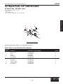
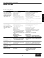
1
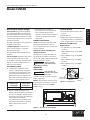
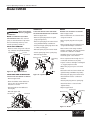
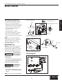
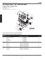
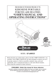
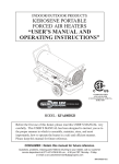
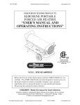
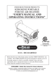
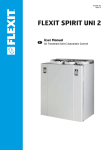
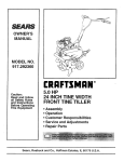
3VE53H
Operating Instructions & Parts Manual
Please read and save these instructions. Read carefully before attempting to assemble, install, operate or maintain the product described.
Protect yourself and others by observing all safety information. Failure to comply with instructions could result in personal injury and/or
property damage! Retain instructions for future reference.
Dayton Portable Oil-Fired
Heater
®
Description
Dayton Model 3VE53H heater is a 400,000 BTU/Hr heater. This heater uses 1-K
Kerosene for combustion, and electricity to run the fan. It is primarily intended for
temporary heating of well ventilated buildings under construction, alteration, or
repair. This heater may be used in agricultural, industrial and commercial
environments.
Specifications
ELECTRICAL SPECIFICATIONS
Model
Electrical Input
Amperage
Fuse
Spark Plug Gap
3VE53H
120V, 60 Hz
4.4
250V/20 amp
.140”
(3.5mm)
Figure 1 – Model 3VE53H
GENERAL SPECIFICATIONS
Model
Type of
Fuel
Input
Rating
Pump
Pressure
Fuel Tank
Capacity
Fuel
Consumption
Size
LxWxH
3VE53H
1-K Kerosene
400,000 BTU/Hr
125 PSI
29.0 Gallons
3.0 Gal/Hr
52.5” x 31.4” x 32.8” 150 (68)
Table of Contents
Page
Description . . . . . . . . . . . . . . . . . . . . . . . 1
Specifications . . . . . . . . . . . . . . . . . . . . . 1
Introduction . . . . . . . . . . . . . . . . . . . . . . 1
Unpacking . . . . . . . . . . . . . . . . . . . . . . . 1
General Safety Information . . . . . . . . 1-2
Product Features . . . . . . . . . . . . . . . . . . 3
Assembly . . . . . . . . . . . . . . . . . . . . . . . 4-5
Kerosene (1-K or
Number 1 Fuel Oil). . . . . . . . . . . . . . . . 4
Overview of Heater Design . . . . . . . . . 5
Fueling Your Heater . . . . . . . . . . . . . . 5
Operation . . . . . . . . . . . . . . . . . . . . . . 5-6
Long-Term Storage . . . . . . . . . . . . . . . 6
Maintenance . . . . . . . . . . . . . . . . . . . . 6-9
Replacing Fuse. . . . . . . . . . . . . . . . . . . . 9
Wiring Diagram . . . . . . . . . . . . . . . . . . . 9
Repair Parts Illustration
Model 3VE53H. . . . . . . . . . . . . . 10, 12-14
Repair Parts List Model 3VE53H . . . 11-14
Troubleshooting Chart . . . . . . . . . . . . 15
Warranty Information . . . . . . . . . . . . . 16
Introduction
Please read this USER'S MANUAL
carefully. It will show you how to
assemble, maintain and operate this
heater safely and efficiently to obtain
the full benefits of its many features.
Consumer: retain these instructions for
future reference.
Unpacking
1. Remove all packing items applied to
heater for shipment.
2. Remove all items from carton.
32.8"
Weight
Lbs. (kg)
3. Check all items for shipping damage.
If heater is damaged, promptly inform
dealer where you purchased heater.
General Safety Information
Indicates an imminently hazardous
situation which, if not avoided, WILL
result in death or serious injury.
DANGER
Indicates a potentially hazardous
situation which, if not avoided, COULD
result in death or serious injury.
WARNING
Indicates a potentially hazardous
situation which, if not avoided, MAY
result in minor or moderate injury.
CAUTION
Before using this
heater, please read
this USER'S MANUAL very carefully. This
USER'S MANUAL has been designed to
instruct you as to the proper manner in
which to assemble, maintain, store, and
most importantly, how to operate the
heater in a safe and efficient manner.
CAUTION
CAUTION
Never leave the
heater unattended
while burning!
52.5"
31.4"
Figure 2 – Heater Dimensions
Form 5SXXXX
Printed in U.S.A.
XXXXX
XXXX/XXX/XXXXX
XXXXXX
XX/XX
®
3VE53H
Dayton Operating Instructions and Parts Manual
Dayton Portable Oil-Fired Heater
®
E
N
G
L
I
S
H
General Safety Information
(Continued)
Improper use of this
heater can result in
serious injury or death from burns, fire,
explosion, electrical shock, and/or
carbon monoxide poisoning.
DANGER
For optimal performance of this heater,
it is strongly suggested that 1-K kerosene be used. 1-K kerosene has been
refined to virtually eliminate contaminants, such as sulfur, which can cause
a rotten egg odor during the operation
of the heater. However, #1 or #2 fuel oil
(diesel fuel) may also be used if 1-K
kerosene is not available. Be advised
that these fuels do not burn as clean as
1-K kerosene, and care should be taken
to provide more fresh air ventilation to
accommodate any added contaminants
that may be added to the heated space.
Use of #1 or #2 fuel oil will require
increased maintenance of unit.
CAUTION
Risk of indoor air
pollution!
- Use this heater only in well ventilated
areas! Provide at least a three square
foot (2,300 sq cm) opening of outside
air for every 100,000 BTU/hr of heater
rating.
- People with breathing problems
should consult a physician before
using the heater.
- Carbon Monoxide Poisoning: Early
signs of carbon monoxide poisoning
resemble flu-like symptoms such as
headaches, dizziness, and/or nausea. If
you have these symptoms, your heater
may not be working properly.
- Get fresh air at once! Have the heater
serviced. Some people are more
affected by carbon monoxide than
others. These include pregnant
women, those with heart or lung
problems, anemia, or those under
the influence of alcohol, or at high
altitudes.
- Never use this heater in living or
sleeping areas.
CAUTION
Risk of Burns/Fire/
Explosion!
- Use 1-K kerosene in this heater. #1 fuel
oil is a suitable substitute.
- NEVER use fuels such as gasoline,
benzene, paint thinners, or other oil
compounds in this heater (RISK OF
FIRE OR EXPLOSION).
- NEVER use this heater where
flammable vapors may be present.
- NEVER refill the heater's fuel tank
while heater is operating or still hot.
This heater is EXTREMELY HOT while
in operation.
- Keep all combustible materials away
from this heater.
Minimum Clearances
Outlet
8 feet (250 cm)
Sides, Top and Rear 4 feet (125 cm)
- NEVER block air inlet (rear) or air
outlet (front) of heater.
- NEVER use duct work in front or at
rear of heater.
- NEVER move or handle heater while
still hot.
- NEVER transport heater with fuel in
it's tank.
This heater is equipped with a thermostat and may start at any time.
- ALWAYS locate heater on a stable and
level surface.
- ALWAYS keep children and animals
away from heater.
For Technical Support or Troubleshooting, Call: 1-800-323-0620
2
- Bulk fuel storage should be a
minimum of 25 ft. from heaters,
torches, portable generators, or other
sources of ignition.
All fuel storage should be in accordance
with federal, state, or local authorities
having jurisdiction.
CAUTION
Risk of Electric
Shock!
- Use only the electrical power (voltage
and frequency) specified on the model
plate of the heater. Use only a threeprong, grounded outlet and extension
cord.
- ALWAYS install the heater so that it is
not directly exposed to water spray,
rain, dripping water, or wind.
- ALWAYS unplug the heater when not
in use.
CALIFORNIA RESIDENTS:
This heater produces carbon
monoxide, which is listed by the State
of California as a reproductive toxin
under Proposition 65.
MASSACHUSETTS RESIDENTS:
Massachusetts state law prohibits the
use of this heater in any building
which is used in whole or in part for
human habitation. Use of this heating
device in Massachusetts requires local
fire dept. permit (M.E.L.C. 148, Section
10A).
CANADIAN RESIDENTS:
Use of this heater shall be in
accordance with authorities having
jurisdiction and CSA Standard B139.
NEW YORK CITY RESIDENTS:
For use only at construction sites in
accordance with applicable NYC codes
under NYCFD certificate of approval
#5037.
Dayton Operating Instructions and Parts Manual
Model 3VE53H
Product Features
Hot Air Outlet
E
N
G
L
I
S
H
Front Handle
Upper Shell
Rear Handle
Lower Shell
Cord Wrap
Fuel Gauge
Fan Guard
Fuel Cap
Lamp
Fuel Tank
Thermostat Knob
Room Temp. Display
Fuel Drain Bolt
Extra Electric Outlet
Operating Switch
Power Cord
Figure 3 – Model 3VE53H Features
Wheels
Cord Wraps
Screw (L)
Cap Nuts
Screw (S)
Bushing
Nut
Washers Cap Nuts(S)
Hardware Kit Part No: HW-KFA1019
Front Handle
Rear Handle
Wheel Support Frame
Threaded Axle
Figure 4 – Component Identification
For Technical Support or Troubleshooting, Call: 1-800-323-0620
3
®
3VE53H
Dayton Operating Instructions and Parts Manual
Dayton Portable Oil-Fired Heater
®
E
N
G
L
I
S
H
Assembly
Screw (L)
TOOLS REQUIRED
• Medium Phillips screwdriver
Handle
Screw (S)
• 24mm socket or adjustable wrench.
Cap Nut (S)
ASSEMBLING WHEEL & HANDLE
1. Slide threaded axle through the rear
sectioon of the wheel support frame.
2. Slide one axle bushing on to each side
of the axle. Slide one wheel on to each
side of the axle. Attach one cap nut on
to each side of the threaded axle and
tighten well.
Cord Wrap
Screw (S)
Fuel Tank Flange
Wheel Support Frame
3. Place heater on wheel support frame.
Make sure air inlet end (rear) of
Wheel
heater is over wheels. Align the holes
Air Inlet
on fuel tank flange. Insert screws(L)
Washer
through handles (front and Rear), fuel
tank flange, and wheel support frame.
Cap Nut (L)
Threaded Axle
Insert screws(S) through rear handle,
Bushing
fuel tank flange, and washer(S) as
shown in figure 5 and attach nut finger
Figure 5 – Wheel and Handle Assembly
tight after each screw is inserted.
4. After all screws are inserted, tighten
nuts firmly.
5. Align the hole on the rear handle
with the mounting hole on the cord
wrap.
6. Insert screws through cord wrap, rear
handle as shown in Figure 5 and
attach nut finger tight after each
screw is inserted.
7. After all screws are inserted, tighten
nuts firmly.
DO NOT operate
heater without
support frame fully assembled to tank.
CAUTION
KEROSENE (1-K)
For optimal performance of this heater,
it is strongly suggested that 1-K kerosene be used. 1-K kerosene has been
refined to virtually eliminate contaminants, such as sulfur, which can cause a
rotten egg odor during the operation
of the heater. However, #1 or #2 fuel oil
(diesel fuel) may also be used if 1-K
kerosene is not available. Be advised
that these fuels do not burn as clean as
1-K kerosene, and care should be taken
to provide more fresh air ventilation to
accommodate any added contaminants
that may be added to the heated space.
NOTE: Kerosene should only be stored
in a blue container that is clearly
marked “kerosene”. Never store
kerosene in a red container. Red
containers are associated with gasoline.
For Technical Support or Troubleshooting, Call: 1-800-323-0620
4
- NEVER store kerosene in the living
space. Kerosene should be stored in a
well ventilated area outside the living
area.
- NEVER use fuel such as gasoline,
benzene, alcohol, white gas, camp
stove fuel, paint thinners or other oil
compounds in this heater (THESE ARE
VOLATILE FUELS THAT CAN CAUSE A
FIRE OR EXPLOSION).
- Use 1-K kerosene in this heater. #1 or
#2 fuel oils are a suitable substitute.
- NEVER store kerosene in direct
sunlight or near a source of heat.
- NEVER use kerosene that has been
stored from one season to the next.
Kerosene deteriorates over time. OLD
KEROSENE WILL NOT BURN PROPERLY
IN THIS HEATER.
Dayton Operating Instructions and Parts Manual
Model 3VE53H
Overview of Heater Design
Fuel System: This heater is equipped
with a fuel pump (Gear) that pulls fuel
through the fuel line connected to the
fuel tank and then pushes fuel through
a filter and a solenoid valve and out the
burner head nozzle.
C. Flame-Out Sensor: Utilizes a
photocell to monitor the flame in
burn chamber during normal
operation. It will cause the heater to
shut off should the burner flame
extinguish.
FUELING YOUR HEATER
TO START HEATER
2. Attach fuel cap.
3. Plug power cord into three-prong,
grounded extension cord. Extension
cord must be at least six feet long.
This fuel is sprayed into the combustion
chamber in a fine mist.
NEVER fill the heater fuel tank in the
living space: fill the tank outdoors.
“SureFire Ignition”: The electronic
ignitor sends voltage to a specially
designed spark plug.
Do not overfill your heater and be sure
heater is leveled.
Extension Cord Wire Size
Requirements:
• 6 to 100 feet long, use 14 AWG
conductor.
Important notice regarding first
ignition of heater:
• 101 to 200 feet long, use 12 AWG
conductor.
The first time you light the heater, it
should be done outdoors. This allows
the oils, etc. used in manufacturing the
heater to burn off outside.
• 201 to 300 feet long, use 10 AWG
conductor.
The spark plug ignites the fuel and air
mixture.
The Air System: The heavy duty motor
turns a fan that forces air into and
around the combustion chamber. Here,
the air is heated and then forced out
the front of the heater.
THE SAFETY SYSTEM
A. Temperature Limit Control: This
heater is equipped with a Temperature Limit Control designed to turn
off the heater should the internal
temperature rise to an unsafe level.
If this device activates and turns your
heater off, it may require service.
Internal Shut-Off
Temperature
+/-10 degrees
176°F (80°C)
Reset
Temperature
+/-10 degrees
122°F (50°C)
Never refill fuel
tank when heater
is operating or still hot.
WARNING
Operation
E
N
G
L
I
S
H
1. Fill fuel tank with kerosene or No. 1
fuel oil.
• 301 to 400 feet long, use 8 AWG
conductor.
• 401 to 500 feet long, use 6 AWG
conductor.
Lamp
VENTILATION
Risk of indoor air
pollution. Use heater
only in well ventilated areas.
CAUTION
Provide a fresh air opening of at least
twelve square feet.
NOTE: If more heaters are being used,
provide a fresh air opening of at least
three square feet for each 100,000
BTU/Hr. rating.
Thermostat
Control Knob
Room Temp.
Display
Operating
Switch
Figure 7 – Control Parts
B. Electrical System Protection: This
heater’s electrical system is protected
by a fuse mounted to the PCB Assembly that protects it and other electrical
components from damage.
If yourheater fails to operate, check
this fusefirst and replace as needed.
Refer toSpecification chart on
page 1.
Figure 6 – Overview of Heater Design
For Technical Support or Troubleshooting, Call: 1-800-323-0620
5
®
3VE53H
Dayton Operating Instructions and Parts Manual
Dayton Portable Oil-Fired Heater
®
E
N
G
L
I
S
H
Operation (Continued)
4. Turn “THERMOSTAT CONTROL
KNOB” to desired setting (setting
range: 40°F-110°F, 9 step) and push
operating switch to “ON” position.
Power indicator lamp and room
temperature display will light and
heater will start.
If heater does not start, the thermostat setting may be too low, turn
“THERMOSTAT CONTROL KNOB” to
higher position to start heater. If heater
still does not start, turn operating switch
to“OFF” and then to “ON” position (See
Figure 7). If heater still does not start,
see Troubleshooting Chart on page 15.
NOTE: Room Temp. display indicates as
following:
- When room temp. is less than 0°F: “Lo”.
1. Turn operating switch to “OFF”.This
will cause heater flame to go out.The
motor will continue to run during
the cooling cycle.
(Room Temp. Display will show “CC”
during the cooling cycle)This allows
the fan to cool the combustion
chamber. When the cooling
cycle(approx.1Min) is finished, the
motor will stop. Do not unplug
heater until cooling cycle is finished.
2. Unplug power cord.
3. To temporarily stop heaters, set
thermostat at a temperature lower
than air around heater, Heater will
cycle back on if air temperature
around heater matches thermostat
setting.
TO RESTART HEATER
- When room temp. is between 0°F and
99°F: Indicates temp. figure.
DO NOT restart
heater until
cooling cycle is finished.
- When room temp. is more than 99°F:
“HI”.
The cooling cycle cools the combustion
chamber.
NOTICE : The major electrical components of this heater are protected by a
safety fuse mounted to the PCB
board.If your heater fails to start, check
this fuse first and replace as necessary.
You should also check yourpower
source to insure that proper voltage
and frequency are being supplied to
the heater.
1. Wait until cooling cycle is finished
after stopping heater.
TO STOP HEATER
• Don't plug and use an appliance with
more than 5A current in this outlet.
CAUTION
Never unplug heater
while heater is running.
Heater must go through cooling cycle.
The cooling cycle cools the combustion
chamber. Damage to heater can occur if
combustion chamber is not cooled. Do
not restart heater until cooling cycle is
complete.
CAUTION
2. Repeat steps under TO START
HEATER.
EXTRA ELECTRIC OUTLET
WARNING
SHOCK HAZARD!
• Always cover electrical outlet when
not in use. See Figure 8.
LONG-TERM STORAGE OF HEATER
1. Remove fuel drain bolt from rear
bottom side of fuel tank using 3/4”
socket or adjustable wrench anddrain.
2. Using a small amount of kerosene,
swirl and rinse the inside of the tank.
For Technical Support or Troubleshooting, Call: 1-800-323-0620
6
Cover
Electric
Outlet
Figure 8 – Extra Electric Outlet
NEVER mix water with the kerosene as
it will cause rust inside the tank.
IMPORTANT : Do not store kerosene
over summer months for use during
next heating season.Using old fuel
could damage heater.
3. Reinstall Fuel Drain Bolt to Fuel tank
and tighten firmly using 3/4” socket
or adjustable wrench.
Seal
Fuel Drain Bolt
Figure 9. Drain Bolt
IMPORTANT : Before reinstalling the
fuel drain bolt, make sure the seal is on
the bolt. If the seal isnot used the bolt
cannot be installed correctly and the
fuel tank will leak.
4. Store heater in dry well ventilated
area. Make sure storage place is free
of dust and corrosive fumes.
5. Store the heater in the original box
with the original packing material
and keep the USER’S MANUALwith
the heater.
Dayton Operating Instructions and Parts Manual
Model 3VE53H
Maintenance
WARNING
Never service heater
while it is plugged in
or while hot!
NOTE: USE ORIGINAL EQUIPMENT
REPLACEMENT PARTS. Use of thirdparty or other alternate components
will void warranty and may cause
unsafe operating conditions.
UPPER SHELL REMOVAL
- Remove screws along each side and
top of heater using medium Phillips
screwdriver.
Screw
Upper Shell
SPARK PLUG
NOZZLE
CLEAN AND REGAP EVERY 600 HOURS
OF OPERATION OR REPLACE AS NEEDED.
REMOVE DIRT IN NOZZLE AS NEEDED.
- Remove upper shell.
- Remove fuel line from solenoid valve
using 1/4” wrench.
- Remove spark plug wire from spark
plug (See Figure 12).
- Remove spark plug from burner head
using medium Phillips screwdriver.
- Clean and regap spark plug electrodes
to .140” (3.5 mm) gap.
- Reinstall spark plug into burner head.
- Attach spark plug wire to spark plug.
- Remove upper shell.
- Remove spark plug wire from spark
plug.
- Remove spark plug from burner head
using medium Phillips screwdriver.
- Remove five screws using medium
Phillips screwdriver and remove burner
head from combustion chamber.
- Carefully remove nozzle from burner
head using 5/8” socket wrench.
- Reinstall upper shell.
Burner Head Spark Plug
E
N
G
L
I
S
H
Spark Plug
Wire
- Blow compressed air through face of
nozzle (this will remove any dirt).
- Inspect nozzle for damage. If damaged
or clogged, replace nozzle.
- Make sure plug is in place on burner
head.
Gap
Figure 10 – Upper Shell Removal
FAN BLADES AND AIR DEFLECTOR
Figure 12 – Spark Plug
CLEAN EVERY SEASON OR AS NEEDED.
- Reinstall nozzle into burner head and
tighten firmly (175-200 inch-pounds).
- Reinstall spark plug into burner head.
- Remove upper shell.
- Attach burner head to combustion
chamber.
- Clean fan blades and air deflectors
using soft cloth moistened with
kerosene or solvent.
- Attach fuel line to solenoid valve.
Tighten firmly.
- Attach spark plug wire to spark plug.
- Dry fan blades and air deflectors
thoroughly.
- Replace upper shell.
- Reinstall upper shell.
Burner Head
Air Deflector
Spark Plug
Spark Plug
Wire
Fan Blade
Nozzle
Plug
Fuel Line
Figure 13 – Nozzle
Figure 11 – Fan Blades and Air Deflectors
For Technical Support or Troubleshooting, Call: 1-800-323-0620
7
®
3VE53H
Dayton Operating Instructions and Parts Manual
Dayton Portable Oil-Fired Heater
®
E
N
G
L
I
S
H
Maintenance (Continued)
PHOTOCELL
Burner Head
Pump
Screw
Fuel Line(B)
CLEAN PHOTOCELL ANNUALLY OR AS
NEEDED.
- Remove upper shell (See page 7).
- Remove photocell from photocell
bracket and disconnect photocell from
connector.
- Clean photocell lens with cotton swab.
- Inspect photocell for damage. If
damaged, replace photocell.
Photocell Bracket
Solenoid
Valve
Shell Lower
Fuel Line (A)
Fuel Line (B)
Figure 15 – Tighten Fuel Line
Figure 17 – Remove Tank Fuel Filter
Fan Guard
Photocell
Connector
Screw
Photocell Lens Install Photocell
1) Incorrect
2) Correct
Figure 14 – Clean Photocell Lens
FUEL LINES
TIGHTEN FUEL LINES ANNUALLY OR
AS NEEDED.
- Remove upper shell (See page 7).
- Use 1/4” wrench and tighten fuel line
(A) at solenoid valve and at pump (See
Figure 16).
- Remove fan guard (See Figure 16).
- Use 3/8” wrench and tighten fuel line
(B) at pump and pump fuel filter
assembly.
- Reinstall fan guard.
Flat Washer
Figure 16 – Remove Fan Guard
FUEL FILTER
CLEAN TWICE PER HEATING SEASON OR
AS NEEDED.
Tank Fuel Filter
- Remove fan guard (See Figure 16).
- Disconnect fuel line (B) from pumpand
pump fuel filter assembly with3/8”
wrench (See Figure 17).
- Remove two screws that fix bracketfilter to shell lower and remove
bracket-filter.
- Carefully pry fuel filter loose from
fueltank with flat end of screwdriver.
- Wash fuel lines and fuel filter
withclean kerosene.
- Replace fuel filter into fuel tank.
- Replace bracket-filter to shell lower.
- Connect fuel lines (B) to pump
andpump fuel filter assembly.
- Reinstall fan guard.
For Technical Support or Troubleshooting, Call: 1-800-323-0620
8
Fuel Filter
Bracket-Filter
Pump Fuel Filter Assembly
Pump Fuel Filter
- Remove fan guard (See Figure 16).
- Unscrew filter bottom clockwise
fromfilter top with adjustable pliers.
- Remove fuel filter, gasket, magnetfrom filter bottom (See Figure 18).
- Wash filter bottom with clean
kerosene.
- Wipe inside of filter bottom dry with
clean cloth.
- Wash Fuel filter in clean kerosene.
- Remove dirt attached to magnet.
- Put clean magnet, fuel filter andgasket
back in filter bottom.
- Tighten firmly.
Filter Top
Gasket
Fuel Filter
Magnet
Filter
Bottom
Figure 18 – Fuel Pump Filter
PUMP PRESSURE ADJUSTMENT
- Remove pressure gauge plug frompump with 1/8” Allen wrench.
- Install accessory pressure gauge
topressure gauge port (See Figure 19).
Dayton Operating Instructions and Parts Manual
Model 3VE53H
Maintenance (Continued)
Pressure Gauge Plug
- Adjust pressure (Using small flat blade
screwdriver). Turn pressure adjustment
screw clockwise to increase pressure.
Turn screw counterclockwise to
decrease pressure.
E
N
G
L
I
S
H
Pressure Gauge Port
- Start heater (See Operation, Page 5).
Allow motor to reach full speed.
Pressure Adjustment Screw
Pressure Gauge
- Set pump pressure at 125 PSI.
- Stop heater (See Operation, Page 6).
- Remove pressure gauge. Replace
pressure gauge plug in pressure gauge
port.
Pump
Figure 19 – Adjusting Pump Pressure
NOTE: Use only original equipment
replacement parts. Use of alternate or
third party components will void
warranty and may cause an unsafe
operating condition.
Fuse
Fuse Cover
REPLACING FUSE
NOTE: The heater is fuse protected. If
your heater fails to ignite, DO NOT
RETURN YOUR HEATER TO THE STORE.
Wiring Diagram
CONTROL PCB
BLACK CN7
- Unplug heater.
- Turn Fuse Cover COUNTERCLOCKWISE
45° using a flat blade screwdriver and
remove Fuse from Fuse Holder.
- Replace Fuse with enclosed fuse.
FIRE HAZARD. To
avoid fire, Do not
substitute with a higher or lower
current rating.
POWER LAMP
(LED)
THERMOSTAT
(TEMP. CONTROL)
NOTE: Specified fuse rating: AC 250/20A
RED CN3
SOL.
VALVE
BLACK
WHITE
WHITE
BLACK SPARK PLUG
IGNITOR
ORANGE
RED
BLACK
BLACK
PUMP
MOTOR WHITE
CAPACITOR
45uF/400Vac
CN2(AC2)/ WHT
CN8
CN5
WARNING
- Turn Fuse Cover CLOCKWISE 45° using
a flat blade screwdriver while slightly
pushing.
WHITE CN4
LIMIT
CONTROL
BLACK
YEL
WHITE
WHITE
PHOTOCELL
YEL
CN1(AC1)/
CN6
BLK
BLUE
BLUE
OPERATING SWITCH ROOM SENSOR
WHITE
SHOCK HAZARD. To
prevent personal
injury, unplug the power cord before
replacing fuse.
WARNING
Figure 20 – Replacing Fuse
BLACK
Please follow the simple instructions
below to inspect and change the fuse.
Fuse Holder
BLACK
POWER
PLUG
BLACK
AC120V
60Hz
WHITE
GREEN
GREEN
FUSE
20A/250VAC
ELECTRIC
EARTH
OUTLET
EARTH
Figure 21 – Wiring Diagram Model 3VE53H
For Technical Support or Troubleshooting, Call: 1-800-323-0620
9
®
3VE53H
Dayton Operating Instructions and Parts Manual
For Repair Parts, call 1-800-323-0620
24 hours a day – 365 days a year
Please provide following information:
-Model number
-Serial number (if any)
-Part description and number as shown in parts list
19
46
E
N
G
L
I
S
H
22
23
32
20
29
19
24
28
16
26
27
41
15
16
19
33
25
19
19
1
5
44
19
21
19
45
16
19
17
32
21
3
31
34
4
18
8
40
43
7
35
42
11
36
14
19
37
38
39
12
13
9
10
Figure 22 – Repair Parts Illustration for Portable Oil-Fired Heater
For Technical Support or Troubleshooting, Call: 1-800-323-0620
10
2
19
6
Dayton Operating Instructions and Parts Manual
Model 3VE53H
Repair Parts List for Portable Oil-Fired Heater
Ref.
No.
Description
Part
No.
Qty.
Ref.
No.
Description
Part
No.
1
2
3
4
5
6
7
8
9
10
11
12
13
14
15
16
17
18
19
20
21
22
23
Fuel Tank Assembly
Fuel Drain Bolt
Fuel Gauge
Fuel Filter
Fuel Cap
Filler Neck Assembly
Space Support
Card Support
Cord Bushing
Power Cord
Bushing Grommet
Electric Outlet Assembly
Cover Outlet
Screw-Top Table
Lower Shell
Bushing Grommet
Fuel Line
Harness Burner
Flange Screw
Cone-Outside
Clip-Nut
Combustion Chamber
Air Deflector
2151-0010-00
4329-0072-00
2156-0053-00
3221-0009-00
2151-0003-00
2155-0007-00
3713-0004-00
3713-0016-00
3712-0013-00
3980-0087-00
3231-0121-00
39D0-0780-00
3231-0114-00
4319-0042-00
3111-0195-01
3712-0004-00
3740-0031-00
39D0-0781-00
4319-0015-00
2153-0012-00
3131-0182-00
2152-0037-00
3131-0306-00
1
1
1
1
1
1
1
1
1
1
1
1
1
1
1
1
1
1
26
1
14
1
4
24
25
26
27
28
29
30
31
32
33
34
35
36
37
38
39
40
41
42
43
44
45
46
Air Deflector
Burner Head Assembly
Photocell Bracket
Photocell Assembly
Screw (BH1)
Temperature Limit Control
Screw (PH2S)
Ignitor
Ignitor Cover
Motor and Pump Assembly
P.C.B. Assembly
Cover Display
Window Display
Operating Switch
Fuse Holder
Fuse
Guard Safety Assembly
Bracket-Filter
Mesh Guard
Impeller Washer
Fan Assembly
Bolt Standard Socket
Upper Shell
3131-0307-00
See Figure 22
3131-0159-00
SP-KFA1025
4311-0068-00
38C0-0032-00
4312-0021-00
39E0-0021-00
3131-0309-00
See Figure 23
215A-0056-00
3121-0587-00
3231-0113-00
39A0-0209-00
3930-0012-00
3920-0061-00
2153-0011-00
3131-0465-00
3121-0336-00
3131-0240-00
2154-0021-00
4323-0005-00
3111-0196-01
For Technical Support or Troubleshooting, Call: 1-800-323-0620
11
Qty.
1
1
1
1
2
1
2
1
1
1
1
1
1
1
1
1
1
1
1
3
1
1
1
®
E
N
G
L
I
S
H
3VE53H
Dayton Operating Instructions and Parts Manual
For Repair Parts, call 1-800-323-0620
24 hours a day – 365 days a year
Please provide following information:
-Model number
-Serial number (if any)
-Part description and number as shown in parts list
6-1
2
6-2
6-3
E
N
G
L
I
S
H
3
6-2
1
5
6-3
6-5
6-6
4
Assembly Parts
6-4
Figure 23 – Repair Parts Illustration for Portable Oil-Fired Heaters
Repair Parts List for Portable Oil-Fired Heaters
Reference
Number
1
2
3
4
5
6
6-1
6-2
6-3
6-4
6-5
6-6
6-7
Description
Wheel Support Frame
Handle
Cord Wrap
Threaded Axle
Wheel
Hardware Kit
Screw (L)
Screw (S)
Nut
Cap Nut(S)
Bushing
Flat Washer
Cap Nut(L)
Part Number for Model 3VE53H
3551-0098-00
3551-0036-00
3221-0052-00
3541-0093-00
3720-0004-00
HW-KFA1019
INCLUDED IN HARDWARE KIT
INCLUDED IN HARDWARE KIT
INCLUDED IN HARDWARE KIT
INCLUDED IN HARDWARE KIT
INCLUDED IN HARDWARE KIT
INCLUDED IN HARDWARE KIT
INCLUDED IN HARDWARE KIT
For Technical Support or Troubleshooting, Call: 1-800-323-0620
12
Quantity
1
2
2
1
2
1
6
6
8
4
2
2
2
3VE53H
Dayton Operating Instructions and Parts Manual
For Repair Parts, call 1-800-323-0620
24 hours a day – 365 days a year
Please provide following information:
-Model number
-Serial number (if any)
-Part description and number as shown in parts list
E
N
G
L
I
S
H
7
3
2
5
6
1
4
9
8
10
Burner Head Assembly
Figure 24– Repair Parts Illustration for Portable Oil-Fired Heaters
Repair Parts List for Portable Oil-Fired Heaters
Reference
Number
Description
Part Number for Model 3VE53H
Quantity
1
2
3
4
5
6
7
8
9
10
Burner Head
Plug
Nozzle
Spark Plug
Fiber Washer
Spring Washer
Flange Bolt
Nipple-Straight
Solenoid Valve
Elbow Male
3531-0012-00
3541-0060-00
SP-KFA1024
SP-KFA1009
4349-0017-00
4342-0009-00
4329-0013-00
3541-0057-00
39A0-0084-00
3740-0037-00
1
1
1
1
1
1
1
1
1
1
For Technical Support or Troubleshooting, Call: 1-800-323-0620
13
®
3VE53H
Dayton Operating Instructions and Parts Manual
For Repair Parts, call 1-800-323-0620
24 hours a day – 365 days a year
Please provide following information:
-Model number
-Serial number (if any)
-Part description and number as shown in parts list
E
N
G
L
I
S
H
1
7
3
5
6
13
9
12
11
8
15
2
4
10
14
Motor and Pump Assembly
Figure 25 – Repair Parts Illustration for Portable Oil-Fired Heater
Repair Parts List for Portable Oil-Fired Heater
Reference
Number
Description
Part Number for Model 3VE53H
Quantity
1
2
3
4
5
6
7
8
9
10
11
12
13
14
15
Motor
Support-Motor
Bolt (HH)
Lock Nut
Coupling-Pump
Gear Pump
Bolt-Headless Socket
Filter Oil Assembly
Elbow-Male
Fitting-Straight
Holder-Condensor
Bushing Grommet
Cover Condensor
Flange Screw
Capacitor
3970-0081-00
3121-0334-00
4321-0182-00
4331-0022-00
3531-0013-00
3740-0026-00
4323-0004-00
3740-0034-00
3740-0044-00
3740-0039-00
3131-0295-00
3712-0024-00
3121-0338-00
4319-0015-00
3820-0144-00
1
1
4
4
1
1
1
1
2
1
1
1
1
2
1
For Technical Support or Troubleshooting, Call: 1-800-323-0620
14
Dayton Operating Instructions and Parts Manual
Model 3VE53H
Troubleshooting Chart
Symptom
Possible Cause(s)
Corrective Action
Heater ignites but MAIN
PCB assembly shuts heater
off after a short period of
time. (Indicator lamp is
flickering and room temp.
display indicates “E1”)
1. Wrong pump pressure
2. Dirty fuel filter
3. Dirt in nozzle
4. Dirty photocell lens
5. Photocell assembly not properly
installed. (Not seeing the flame)
6. Bad electrical connection between
photocell and MAIN PCB assembly
7. Defective photocell
8. Temperature limit safety
device is overheated
Heater will not ignite but
motor runs for a short
period of time. (Indicator
lamp is flickering and room
temp. display indicates
“E1”)
1. No fuel in tank
2. Wrong pump pressure
3. Carbon deposits on spark plug
and/or improper gap
4. Dirty fuel filter
5. Dirt in nozzle
6. Water in fuel tank
7. Bad electrical connection between
ignitor and MAIN PCB assembly
8. Ignitor wire is not attached tospark
plug.
9. Defective ignitor
10. Defective solenoid valve
(notopening)
1. Thermostat setting is too low
2. Bad electrical connection between
motor and MAIN PCB assembly
Fan does not turn when
heater is plugged in and
power switch is in the “ON”
position (Indicator lamp is
on or flickering)
1. See Pump Pressure Adjustment, page 9
2. Clean Fuel Filter, see page 8
3. Clean Nozzle, see page 7
4. Clean photocell lens, page 8
5. Make sure photocell boot is properly seated
inbracket, see page 8
6. Check electrical connections. See Wiring Diagram,
page 9
7. Replace photocell, page 7
8. Turn operating switch to “OFF” and allow to cool
(about 10 min.). Then turn operating switch to
“ON” position.
1. Fill tank with kerosene
2. See Pump Pressure Adjustment, page 9
3. See Spark Plug, page 7
4. Clean Fuel Filter, see page 8
5. Clean Nozzle, see page 7
6. Flush fuel tank with clean kerosene, page 6
7. Check electrical connections. See Wiring
Diagram,page 9
8. Attach ignitor wire to spark plug
9. Replace ignitor
10. Check electrical connections and voltage to
solenoid valve. If defective, replace solenoid valve
1. Turn thermostat control knob to a higher setting
2. Check electrical connections. See Wiring Diagram,
page 9
(Indicator lamp is flickering
and room temp. display
indicates “E3”)
1. Room Temp. sensor disconnected
2. Sensor Failure
1. Reconnect sensor. See Wiring Diagram, page 9
2. Replace sensor. See Wiring Diagram, page 9
(Indicator lamp is flickering
and room temp. display
indicates “E2”)
Thermostat switch failure
Replace Main P.C.B.
Heater will not turn-on
(Indicator lamp is off)
1. No electrical power
2. Blown fuse
1. Check to insure heater cord and extension cord are
plugged in. Check power supply.
2. Replace safety fuse on cover
display.
For Technical Support or Troubleshooting, Call: 1-800-323-0620
15
®
E
N
G
L
I
S
H
3VE53H
Dayton Operating Instructions and Parts Manual
Dayton Portable Oil-Fired Heater
®
E
N
G
L
I
S
H
DAILY INSPECTIONS
◊ General visual inspection of loose or damaged items
• Tighten any loose Nuts/Bolts due to vibration and normal usage
• Clear any build-up in fuel filling filter(especially when using diesel) located under the fuel cap
- Replace filling filter if any rips or tears are present.
• Inspect Oil filter (pump filter) for debris gathering in the filter bottom (Page 8 – Figure 18)
◊ General observations of heater during operation
• Sound of the heater burning
- Make sure flame is burning consistently/no sputtering
• Scent while heater is lit
- There should be very little smell **will vary depending on fuel type
- K1 clear kerosene will have virtually no odor while road diesel(#2) may create a more noticeable odor
• Visual check of flame and nose cone
- Flame should be a very bright orange to almost yellow in color (visible from the rear of the unit)
- Nose cone should be glowing a bright red to orange color consistently across the entire surface
- No smoke, soot and/or ash should be exiting the front of the heater at any time
WEEKLY INSPECTIONS
◊ Inspect all fuel supply connections and tighten if necessary (Page 8 – Figures 15-18)
◊ Intake to pump filter and bypass lines(re-tighten w/ 3/8” wrench if needed)
• Output line(3/8” wrench) to solenoid(1/4” wrench)
• Solenoid to burner head(1/4” wrench)
◊ Visually inspect and note any build-up in entire burner area
• Front and rear of fan blades
• Lower and upper shell
• Burner head front(chamber side) and rear
• Spark plug electrodes
• Nozzle front(exposed on chamber side of burner head)
** Depending on the heater’s environment; some of the following maintenance may be needed earlier than 500 hours.
** Situations where dust, debris and/or particulate levels are very high may require maintenance to be performed sooner.
** Lower grade and/or quality of fuel may also cause maintenance to be required earlier.
** If during weekly inspections you find any extreme situations and/or your daily inspections are resulting in an abnormal
sound, flame appearance or odor, please begin the 500 hour maintenance schedule.
** When using compressed/pressurized air for cleaning, always direct air the opposite direction of fuel flow.
For Technical Support or Troubleshooting, Call: 1-800-323-0620
16
Dayton Operating Instructions and Parts Manual
Model 3VE53H
500HR INSPECTION/MAINTENANCE
E
N
G
L
I
S
H
◊ Inspection and cleaning of all filters
• Fuel Filling Filter under fuel cap “Front Line against contaminants”.
- Clean using compressed air or replace
• Fuel Tank Filter (filler neck assembly) “pump protection” (Page 8 – Figure 17)
- Clean using compressed air or replace
• Oil Filter Assy “pump filter” (Page 8 – Figure 18)
(If cracks are present, or components are not easily cleaned then replace)
- Disassemble entire fuel pump clean and reassemble.
- Filter top and gasket – rinse with fresh fuel oil
- Fuel filter – rinse with fresh fuel oil
- Magnet – wipe clean of dirt and debris
- Filter Bottom – rinse with fresh fuel oil and wipe dry with clean/dry cloth
• Nozzle Filter (Page 7 – Figure 13)
Remove nozzle from burner head using 5/8” socket and unscrew filter from back of nozzle.
Rinse clean with fresh fuel oil.
◊ Inspect and clean burner head assembly and burner area. (Page 13)
• Wipe front and rear of fan blades completely clean (Page 7 – Figure 11)
• Remove and clean burner head components
- Remove spark plug, clean, and re-gap or replace (Page 7 – Figure 12)
- Remove excessive build-up with fine grit sand paper
- Spark plug gap is 0.14”(3.5mm)
- Remove nozzle, clean or replace – (Page 7 – Figure 13)
- Remove nozzle using 5/8” socket
- Tighten to 175~200 inch-pounds
- Blow compressed air through face of nozzle
- If clogs are extreme or nozzle is damaged then replace
• Wipe entire burner head(cast) clean using dry/clean cloth
• Wipe upper and lower shell clean using dry/clean cloth.
◊ Remove photocell and wipe lens clean using dry/clean cloth or cotton swab (Page 8 – Figure 14)
◊ Insert pressure gauge into proper pump port and verify pump pressure. Adjust if necessary (Page 9 – Figure 19)
• 400k – 125 PSI
◊ Remove ignitor cover and clean dust and debris build-up from ignitor housing (Page 10 – Ref. 32)
◊ Remove Drain Bolt (3/4” socket), drain and flush fuel tank with fresh fuel-oil (Page 6 – Figure 9)
YEAR END/STORAGE
◊
◊
◊
◊
◊
Verify all fittings are tight and secure.
Make sure all filters are free of debris
Be sure any foreign material is completely removed from the entire burner head and burner area
Flush(fuel-oil ONLY, NO water) and completely drain fuel tank
Store unit in original packaging in a dry and well-ventilated area, the more consistent the temperature the better
For Technical Support or Troubleshooting, Call: 1-800-323-0620
17
®
Dayton Operating Instructions and Parts Manual
3VE53H
Dayton Portable Oil-Fired Heater
®
E
N
G
L
I
S
H
LIMITED WARRANTY
DAYTON ONE-YEAR LIMITED WARRANTY. DAYTON® PORTABLE OIL-FIRED HEATERS, MODELS COVERED IN THIS MANUAL,
ARE WARRANTED BY DAYTON ELECTRIC MFG. CO. (DAYTON) TO THE ORIGINAL USER AGAINST DEFECTS IN WORKMANSHIP
OR MATERIALS UNDER NORMAL USE FOR ONE YEAR AFTER DATE OF PURCHASE. ANY PART WHICH IS DETERMINED TO BE
DEFECTIVE IN MATERIAL OR WORKMANSHIP AND RETURNED TO AN AUTHORIZED SERVICE LOCATION, AS DAYTON
DESIGNATES, SHIPPING COSTS PREPAID, WILL BE, AS THE EXCLUSIVE REMEDY, REPAIRED OR REPLACED AT DAYTON’S
OPTION. FOR LIMITED WARRANTY CLAIM PROCEDURES, SEE “PROMPT DISPOSITION” BELOW. THIS LIMITED WARRANTY
GIVES PURCHASERS SPECIFIC LEGAL RIGHTS WHICH VARY FROM JURISDICTION TO JURISDICTION.
LIMITATION OF LIABILITY. TO THE EXTENT ALLOWABLE UNDER APPLICABLE LAW, DAYTON’S LIABILITY FOR CONSEQUENTIAL
AND INCIDENTAL DAMAGES IS EXPRESSLY DISCLAIMED. DAYTON’S LIABILITY IN ALL EVENTS IS LIMITED TO AND SHALL NOT
EXCEED THE PURCHASE PRICE PAID.
WARRANTY DISCLAIMER. A DILIGENT EFFORT HAS BEEN MADE TO PROVIDE PRODUCT INFORMATION AND ILLUSTRATE
THE PRODUCTS IN THIS LITERATURE ACCURATELY; HOWEVER, SUCH INFORMATION AND ILLUSTRATIONS ARE FOR THE SOLE
PURPOSE OF IDENTIFICATION, AND DO NOT EXPRESS OR IMPLY A WARRANTY THAT THE PRODUCTS ARE MERCHANTABLE,
OR FIT FOR A PARTICULAR PURPOSE, OR THAT THE PRODUCTS WILL NECESSARILY CONFORM TO THE ILLUSTRATIONS OR
DESCRIPTIONS. EXCEPT AS PROVIDED BELOW, NO WARRANTY OR AFFIRMATION OF FACT, EXPRESSED OR IMPLIED, OTHER
THAN AS STATED IN THE “LIMITED WARRANTY” ABOVE IS MADE OR AUTHORIZED BY DAYTON.
Technical Advice and Recommendations, Disclaimer. Notwithstanding any past practice or dealings or trade custom,
sales shall not include the furnishing of technical advice or assistance or system design. Dayton assumes no obligations or
liability on account of any unauthorized recommendations, opinions or advice as to the choice, installation or use of
products.
Product Suitability. Many jurisdictions have codes and regulations governing sales, construction, installation, and/or use of
products for certain purposes, which may vary from those in neighboring areas. While attempts are made to assure that
Dayton products comply with such codes, Dayton cannot guarantee compliance, and cannot be responsible for how the
product is installed or used. Before purchase and use of a product, review the product applications, and all applicable
national and local codes and regulations, and be sure that the product, installation, and use will comply with them.
Certain aspects of disclaimers are not applicable to consumer products; e.g., (a) some jurisdictions do not allow the exclusion
or limitation of incidental or consequential damages, so the above limitation or exclusion may not apply to you; (b) also,
some jurisdictions do not allow a limitation on how long an implied warranty lasts, consequently the above limitation may
not apply to you; and (c) by law, during the period of this Limited Warranty, any implied warranties of implied
merchantability or fitness for a particular purpose applicable to consumer products purchased by consumers, may not be
excluded or otherwise disclaimed.
Prompt Disposition. A good faith effort will be made for prompt correction or other adjustment with respect to any
product which proves to be defective within limited warranty. For any product believed to be defective within limited
warranty, first write or call dealer from whom the product was purchased. Dealer will give additional directions. If unable to
resolve satisfactorily, write to Dayton at address below, giving dealer’s name, address, date, and number of dealer’s invoice,
and describing the nature of the defect. Title and risk of loss pass to buyer on delivery to common carrier. If product was
damaged in transit to you, file claim with carrier.
Manufactured for Dayton Electric Mfg. Co.
100 Grainger PKWY.
Lake Forest, Illinois 60045 U.S.A.
®