1
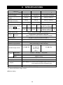
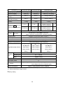
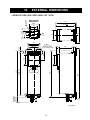
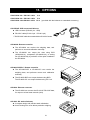
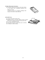
AD-4212C-300
AD-4212C-600
AD-4212C-3000
AD-4212C-6000
AD-4212C-301
AD-4212C-3100
Production Weighing Unit
INSTRUCTION MANUAL
1WMPD4001992B
© 2011 A&D Company, Limited. All rights reserved.
No part of this publication may be reproduced, transmitted, transcribed, or translated
into any language in any form by any means without the written permission of A&D
Company, Limited.
The contents of this manual and the specifications of the instrument covered by this
manual are subject to change for improvement without notice.
Windows and Excel are registered trademarks of Microsoft Corporation.
.
CONTENTS
1.
INTRODUCTION ..........................................................................................................................2
1.1.
Features ........................................................................................................................................ 2
1.2.
Compliance ................................................................................................................................... 5
2.
UNPACKING THE BALANCE .....................................................................................................6
2.1.
Unpacking...................................................................................................................................... 6
2.2.
Installing the Balance .................................................................................................................... 8
3.
PRECAUTIONS .........................................................................................................................10
3.1.
Before Use .................................................................................................................................. 10
3.2.
When Building Into a System .......................................................................................................11
3.3.
During Use .................................................................................................................................. 14
3.4.
After Use...................................................................................................................................... 14
3.5.
Power Supply .............................................................................................................................. 14
4.
OPERATION OF WinCT-AD4212C ...........................................................................................15
4.1.
Changing the Weighing Speed Using WinCT-AD4212C ................................................................... 16
4.2.
Calibration ................................................................................................................................... 16
4.3.
Changing the Baud Rate Using WinCT-AD4212C............................................................................ 18
5.
SMART RANGE FUNCTION .....................................................................................................19
6.
COMMUNICATION SPECIFICATIONS......................................................................................20
7.
MAINTENANCE .........................................................................................................................25
8.
TROUBLESHOOTING ...............................................................................................................26
8.1.
Checking the Balance Performance and Environment ............................................................... 26
8.2.
Asking For Repair........................................................................................................................ 27
9.
SPECIFICATIONS......................................................................................................................28
10.
EXTERNAL DIMENSIONS .....................................................................................................30
11.
OPTIONS................................................................................................................................31
12.
TERMS/INDEX .......................................................................................................................33
1
1. INTRODUCTION
This manual describes how the AD-4212C series balance works and how to get the most out of it in
terms of performance.
Read this manual thoroughly before using the balance and keep it at hand for future reference.
1.1. Features
z A Weighing Unit, suitable for building into a production line system. The weighing unit is
compact, with a width of 59 mm.
z A Super Hybrid Sensor (SHS) is used to provide high resolution and high response speed.
Minimum
weighing
Stabilization time*1
value
AD-4212C-300
320 g
0.001 g
0.5 second (0 - 30 g), 1.0 second (30 - 320 g)
AD-4212C-600
620 g
0.001 g
0.5 second (0 - 30 g), 1.0 second (30 - 620 g)
AD-4212C-3000
3200 g
0.01 g
0.5 second (0 - 300 g), 1.0 second (300 - 3200 g)
AD-4212C-6000
6200 g
0.01 g
0.5 second (0 - 300 g), 1.0 second (300 - 6200 g)
51 g*2
0.0001 g
1.3 seconds
AD-4212C-301
320 g
0.001 g
1.0 second
510 g*2
0.001 g
1.3 seconds
AD-4212C-3100
3200 g
0.01 g
1.0 second
*1 With FAST selected under good environment
*2 Smart range (Refer to “5. SMART RANGE FUNCTION”.)
Model
Weighing
capacity
z The AD-4212C series can output the weighing digital data directly. Therefore, the AD-4212C
series (the weighing unit) can be connected to a personal computer or a PLC directly.
z Dust-protected and Protected Against Splashing Water (Complying with IP65). The AD-4212C
series has a patented shock absorber under the weighing pan and can cope with movement in
all directions, protecting the weighing unit from an actuator malfunction.
z Windows Communication Tools (WinCT-AD4212C), allows easy confirming of the weighing
data by using a Windows-based personal computer.
Windows is a registered trademark of the Microsoft Corporation.
z When connected to an optional remote controller, an AD-8922A, AD-8923-BCD or AD-8923-CC,
the remote controller can receive the weighing data and manually perform re-zero and
calibration.
The AD-8922A can output the data using BCD, comparator or analog out by selection of the
option installed in the AD-8922A.
The AD-8923-BCD outputs the data using BCD and the AD-8923-CC outputs the data using
CC-Link.
Note: CC-Link is a high-speed field network able to simultaneously handle both control and
information data.
z When connected to an optional AD-8526 Ethernet converter, it can convert the AD-4212C
RS-232C data, for output to a local area network (LAN).
2
Example 1 (Connecting to a personal computer or an AD-8922A)
AD-4212C
Accessory
RS-232C cable (10 m)
Communication
software
“ WinCT-AD4212C”
USB converter
(Option: AX-USB-9P)
USB port
Personal
computer
AD-8922A
AD-4212C
USB converter
(Option: AX-USB-9P)
Accessory
RS-232C cable (10 m)
Communications cable
(Option: AX-KO1786-200)
3
Personal
computer
Example 2 (Connecting to a PLC)
.
D-sub 9-pin (female)
AD-4212C
Accessory
RS-232C cable (10 m)
PLC
AD-8922A-01
Connection cable*
AD-4212C
BCD input
AD-8922A
PLC
BCD output board
(Option AD-8922A-01)
BCD cable
(Fabricate locally)
* Specify the AD-8922A-01 connection cable when ordering the AD-8922A-01.
AX-KO3705-200
AX-KO3705-500
AX-KO3705-1000
2m
5m
10 m
AD-8923-CC
AD-4212C
CC-Link network
Accessory
RS-232C cable (10 m)
To other
remote stations
PLC
AD-4212C
Accessory
RS-232C cable (10 m)
LAN port
AD-8526
LAN cable
4
PLC
1.2. Compliance
Compliance with FCC Rules
Please note that this equipment generates, uses and can radiate radio frequency energy. This
equipment has been tested and has been found to comply with the limits of a Class A
computing device pursuant to Subpart J of Part 15 of FCC rules. These rules are designed to
provide reasonable protection against interference when the equipment is operated in a
commercial environment. If this unit is operated in a residential area, it may cause some
interference and under these circumstances the user would be required to take, at his own
expense, whatever measures are necessary to eliminate the interference.
(FCC = Federal Communications Commission in the U.S.A.)
Compliance with EMC Directives
This device features radio interference suppression in compliance with valid EC
Regulation 2004/108/EEC.
5
2. UNPACKING THE BALANCE
2.1. Unpacking
The balance is a precision instrument. Unpack the balance carefully. Keep the packing material
to be used for transporting the balance in the future.
When unpacking, see the illustration below to confirm that everything is contained.
AC adapter
jack
Weighing
pan
Screws
(Flat head: M4 X 6)
Pan
support
RS-232C
connector
AC adapter
plug
Grounding
terminal
(See note below.)
Arrow mark
face up
Pan
support
boss
RS-232C cable (10 m)
Breeze
break
Weighing
unit
Leveling foot
Accessories
Windows communication
tools (WinCT-AD4212C)
●
RS-232C cable (10 m)*2
Weighing pan
Pan support
●
Screws (Flat head: M4 X 6)
●
●
*1
AC adapter
Calibration weight 200 g
OIML, Class E2 or equivalent
AC adapter
ID label
*1 Please confirm that the AD adapter type is correct for your local voltage and
receptacle type.
*2 2-m and 5-m cables are available as options. Refer to "10. OPTIONS".
Note
When the AD-4212C series weighing unit is built into a system, be sure to
earth ground the weighing unit using the grounding terminal.
6
ATTACHING THE AD-4212C SERIES WEIGHING UNIT DIRECTLY ON THE MOUNTING BASE
When the AD-4212C series weighing unit is built into a system, remove the three leveling feet and
use the screw holes to secure the weighing unit to the base.
Attachment Procedure
1. Remove the three leveling feet.
Caution
Do not remove any other screws from the
bottom of the weighing unit. Doing so could
damage the weighing sensor.
Weighing
unit
2. Secure the weighing unit from above.
(Prepare appropriate screws with a size
corresponding to an M5 screw. The screw
hole diameter: 6 mm).
Leveling foot
In case of securing the weighing unit from
the under side, use M6 screws with 1-mm
pitch.
To secure
Notes
The screws to secure the weighing unit
to the mounting base are not provided.
For the position of the holes, refer to “10.
EXTERNAL DIMENSIONS”.
When the leveling adjustment is difficult to perform due to the installation conditions, place a
shim between the lower surface of the weighing unit and the securing surface, or use two nuts. If
the adjustment is still difficult to perform, perform calibration before use. Then, the balance will
function normally.
7
2.2. Installing the Balance
Install the balance as follows:
1. Refer to “3. PRECAUTIONS” for installing the balance.
2. Refer to "2-1 Unpacking" on page 6, to attach the pan support and the weighing pan on the
weighing unit.
3. Insert the RS-232C cable into the jack located on the rear of the weighing unit.
Rear of the
weighing unit
When confirming the performance
of the weighing unit using
WinCT-AD4212C, connect the
cable into RS-232C terminal of the
computer.
Arrow mark
face up
D-sub 9-pin
RS-232C cable
How to disconnect the cable from the weighing unit
Slide the connector sleeve in the direction of the arrow to unlock and gently pull the connector
out.
Unlocked
Slide the connector sleeve
in the direction of the arrow
4. Confirm that the AC adapter type is correct for the local voltage and power receptacle type.
5. Plug the AC adapter plug into the AC adapter jack located on the rear of the weighing unit and
plug the AC adapter into the electrical outlet. Warm up the balance for 30 minutes or more with
nothing on the weighing pan.
6. Set the pan unit and I/O unit to adapt to the peripheral system. Set the following for the I/O unit.
RS-232C (Refer to“6. COMMUNICATION SPECIFICATIONS”)
Set the weighing speed to adapt to the ambient conditions.
Note
Make sure that the personal computer is in operation before connecting to the AD-4212C.
7. After the balance has been installed, calibrate the balance using the 200 g calibration weight
provided with the balance. For details, refer to “4.2. Calibration”.
(The AD-4212C-3000/6000/3100 can be calibrated using the 200 g weight.)
8. By removing the provided weighing pan, a locally fabricated weighing pan can be attached to the
AD-4212C series by using the four screw holes (M4 screw x pitch 0.7 mm) on the pan support.
8
MASS OF THE LOCALLY FABRICATED WEIGHING PAN
Design the weighing pan so that the mass falls within the ranges shown in the table below:
Model
Mass of
the weighing pan (g)
20 to 130
Status
Pan support is used (with weighing pan removed)
Pan support boss is used (with the weighing pan
and pan support removed)
Pan support is used (with weighing pan removed)
AD-4212C-600
Pan support boss is used (with the weighing pan
and pan support removed)
Pan support is used (with weighing pan removed)
AD-4212C-3000/3100 Pan support boss is used (with the weighing pan
and pan support removed)
Pan support is used (with weighing pan removed)
AD-4212C-6000
Pan support boss is used (with the weighing pan
and pan support removed)
AD-4212C-300/301
AD-4212C-300/301
When the weighing pan
is removed
320 g
20 g
Mass range
210 g
to be weighed
130 g
Mass
of locally
fabricated pan
3200 g
20 g
Mass range
210 g
to be weighed
Mass range
210 g
to be weighed
620 g
Mass
of locally
fabricated pan
20 g
20 to 6010
70 to 6060
Mass range
210 g
to be weighed
Mass of
locally
fabricated pan
When the weighing pan and
pan support are removed
620 g
Mass range
210 g
to be weighed
460 g
Mass of
locally
70 g fabricated
pan
When the weighing pan
is removed
Mass range
210 g
to be weighed
Mass of
locally
70 g
fabricated pan
70 to 3060
AD-4212C-6000
When the weighing pan and
pan support are removed
3010 g
20 to 3010
410 g
180 g
Mass of
locally
70 g
fabricated pan
3200 g
70 to 460
When the weighing pan
is removed
AD-4212C-3000/3100
When the weighing pan
is removed
20 to 410
AD-4212C-600
When the weighing pan and
pan support are removed
320 g
70 to 180
6200 g
Mass range
210 g
to be weighed
When the weighing pan and
pan support are removed
6200 g
Mass range
210 g
to be weighed
6010 g
3060 g
20 g
Mass of
locally
fabricated pan
6060 g
Mass of
locally
70 g fabricated
pan
Notes
If the balance is to be used in a range other than shown above, contact the local A&D dealer.
To avoid the effects of static electricity or magnetism, use materials other than resin or
magnetic materials when designing a weighing pan.
When a locally fabricated weighing pan is used, the zero point may be shifted greatly
right after the AC adapter is plugged in. Perform re-zero before weighing to cancel the
amount of zero drift as necessary.
9
3. PRECAUTIONS
To get the optimum performance from the balance and acquire accurate weighing data, note the
following:
3.1. Before Use
Install the weighing unit in an environment where the temperature and humidity are not
excessive. The best operating temperature is about 20°C / 68°F at about 50% relative
humidity.
Install the weighing unit where it is not exposed to direct sunlight and it is not affected by
heaters or air conditioners.
Install the weighing unit where it is free of dust.
Install the weighing unit away from equipment which produces magnetic fields.
Install the weighing unit in a stable place avoiding vibration and shock. Corners of rooms on
the first floor are best, as they are less prone to vibration.
Ensure a stable power source when using the AC adapter.
Plug in the AC adapter as usual, and warm up the balance for 30 minutes or more.
Calibrate the balance before use or after having moved it to another location.
In addition, calibrate it periodically to maintain the accuracy.
Caution
Do not install the balance where flammable or corrosive gas is present.
10
3.2.
When Building Into a System
The AD-4212C is a precision balance. When it is built into a system, errors such as unstable weight
values may occur due to static electricity, vibration, sample temperature and magnetism of the
materials weighed or used for the devices near the balance.
When using the balance as part of a system, take the following precautions:
z Precautions when not performing the weighing at the center of the weighing
pan
If not performing the weighing at the center of the weighing pan, design the weighing system so
that the total moment of the support device and the object to be weighed will be the value
specified in the table below. Even a load, with a moment of less than the specified value, when
applied to the balance, may cause the overload protection mechanism to function slowly, to tilt
the weighing pan.
Allowable eccentric load for each model
Model
AD-4212C-300/600/301
AD-4212C-3000/6000/3100
Allowable eccentric load
0.1 Nm or less
0.3 Nm or less
AD-4212C-300/600/301
Example of a system where the total moment of the device and the object is 0.1 Nm or less:
200 g X 0.05 m
AD-4212C-3000/6000/3100
Example of a system where the total moment of the device and the object is 0.3 Nm or less:
300 g X 0.1 m
Note: The values above are for reference and may be different from actual
specifications.
11
Errors due to a static charge and measures to take
When the ambient humidity is less than 45% RH, insulators such as plastic or glass are prone to
static electricity. When charged material comes close to the balance, a pulling force is generated
by static induction between the charged material and the weighing pan. This causes an unstable
weight value.
To protect the balance against a discharge generated by charged material when it comes close
to the balance, be sure to earth ground the weighing unit and the display unit.
Note that static electricity generated by static induction will not be canceled by earth-grounding.
Use a humidifier or the AD-1683 DC static eliminator,
Charged plastic breeze break
Charged sample
The pulling force
causes an unstable
weight value
A pulling force generated between
the charged sample and the balance
causes an unstable weight value.
Measures to take (Plastic is used in the examples below. They can be applied to glass, too.)
When the sample or devices are plastic
Use a static eliminator that generates no air blow such as the
AD-1683, DC static eliminator, to remove static electricity.
Place the sample in a container that is made of a conductive
material such as metal and that can be sealed, and then
weigh it.
When the sample is powdery
When the balance is used in combination with a feeder for
batch weighing of powdery samples, samples may be
charged by rubbing sample particles against each other.
Use a static eliminator and perform weighing while
removing static electricity.
Charged
material
Metal case
Grounding
When the sample container is made of material that is prone to static electricity such as plastic
Cover the outside of the container with a metal such as aluminum foil.
Apply an anti-static agent onto the container.
When making a breeze break using plastic
Apply an anti-static agent onto the breeze break.
Use a conductive acrylic fiber.
When plastic exists in the balance installation site
Cover the plastic with a grounded conductive material.
Apply an anti-static agent onto the plastic.
When an operator is static charged
If an operator’s clothes are static charged, especially in winter, it may be a cause for
unstable weight values.
Wear an anti-static wrist strap.
12
Errors due to air flow and measures to take
Where the influence of ambient air flow is
great such as: close to an air conditioner, door
or passage way. Even very subtle air flow that
is hard to be detected may influence the
weighing operation.
Avoid those areas as a weighing site.
If weighing is to be performed in such an
area, use a breeze break or take other
appropriate measures.
Where the influence of heat or drafts is great
Eliminate
temperature
differences
Draft
between a sample and the environment.
40 C
When a sample is warmer (cooler) than
20 C
the ambient temperature, the sample will
be lighter (heavier) than the true weight.
This error is due to a rising (falling) draft
around the sample.
Do not touch the sample directly with your
hand. Use tweezers or other tools.
If you touch the sample, the same type
error described above will occur.
Do not perform weighing where it is exposed to direct sunlight. Weighing errors may
occur due to sudden temperature change or drafts.
Errors due to vibration and measures to take
Where the influence of vibration is great, such as:
(1) Soft ground (2) Second or higher floor (3) Near center of a floor far from pillars (4) Seismic
isolated structures (5) Near tall buildings.
In the areas listed above, the scale may yield unstable weight values on windy days or after an
earthquake. Especially in case of (4) and (5), weight values may be unstable for a long period of
time because of long lasting low-frequency vibration after strong winds or an earthquake.
Errors due to other causes and measures to take
Change in temperature or humidity
A sudden change in temperature or humidity can generate a draft and cause the balance to
absorb or exude moisture, which leads to unstable displays.
Avoid sudden change in temperature or humidity.
Use an air conditioner or humidifier to control the temperature or humidity.
Magnetic material
The balance uses a strong magnet as part of the balance assembly, so use much care when
weighing magnetic materials.
Place a non-magnetic object such as aluminum or brass between the sample and the
balance to keep an appropriate distance between them while weighing.
13
3.3. During Use
To minimize the affect by electrical noises, earth
ground the weighing unit and the display unit (option).
Do not drop things upon the weighing pan, or place a
sample on the pan that is beyond the balance weighing
capacity. Place a sample in the center of the weighing
pan to minimize corner-load errors.
To prevent possible errors, before each weighing,
perform re-zero using the RS-232C command, or
calculate the difference between the weight value
before and after weighing.
Take into consideration the affect of air buoyancy on a sample when measuring the absolute
value with the minimum weighing value of 0.1 mg.
Even though the scale is dust-protected and protected against splashing water, complying with
IP65, be sure to clean the weighing pan and keep the conditions around the pan clean after
weighing powdery, fluid samples or metallic strips.
3.4. After Use
Avoid mechanical shock to the weighing unit.
Periodically calibrate the balance, using a calibration weight,.
Do not disassemble the weighing unit. Contact the local A&D dealer if the balance needs
service or repair.
Do not use organic solvents to clean the weighing unit. Clean the weighing unit with a lint free
cloth that is moistened with warm water and a mild detergent.
Avoid dust and water so that the weighing unit weighs correctly. Protect the internal parts from
liquid spills and excessive dust.
3.5. Power Supply
When the AC adapter is connected, the balance is in the standby mode if the standby indicator
is on (refer to “4. OPERATION OF WinCT-AD4212C”). This is a normal state and does not
harm the balance. For accurate weighing, plug in the AC adapter and warm up the balance for
the appropriate duration before use.
14
4. OPERATION OF WinCT-AD4212C
The software has the following functions:
- Set the weighing speed
- Set the minimum display value
- Calibration
- Set the baud rate
• The parameters set using these functions, are stored in non-volatile memory, and maintained,
even if the AC adapter is removed,.
- A data logging function, allows confirmation of the weighing data after weighing
Before use
1. Install the WinCT-AD4212C into the computer. For details, refer to Readme of WinCT-AD4212C.
2. Connect one end of the RS-232C cable to the weighing unit RS-232C connector and connect
the other end of the RS-232C cable (D-sub 9-pin) to the personal computer RS-232C terminal.
3. Set the COM port of the WinCT-AD4212C on the personal computer, and press the START
button. The personal computer will display the weight value.
Function of display symbols and buttons
Weighing speed indicators
Processing indicator
Stabilization indicator
Standby indicator
Unit (g)
Weighing data or stored data
Button
When pressed
SAMPLE
Switches between the weighing mode and the standby mode. With the standby mode,
only the standby indicator is displayed. The ON/OFF button is available anytime.
Therefore, if you press the ON/OFF button when operating, the balance switches to the
standby mode.
In the weighing mode, switches the minimum weighing value.
MODE
Changes the weighing speed.
CAL
Enters the calibration mode.
PRINT
(Usually no function. Used in the calibration mode.)
RE-ZERO
Sets the display to zero.
ON/OFF
15
4.1. Changing the Weighing Speed Using WinCT-AD4212C
The weighing speed can be selected from the following three rates to minimize the influence on
weighing that is caused by drafts and/or vibration at the place where the balance is installed.
Indicator
FAST
MID.
SLOW
Speed
Fast
Slow
Weighing speed setting
Stability
Sensitive value
Stable value
Operation
MODE
1. Press the MODE button.
2. Press the MODE button to select a weighing speed.
Either FAST, MID. or SLOW can be selected.
MODE Each pressing
switches
the indicators
4.2. Calibration
Calibration
Calibration using the calibration weight.
Caution
Do not allow vibration or drafts to affect the balance during calibration.
Caution on using an external calibration weight
The accuracy of the weight can influence the accuracy of weighing. Select an appropriate
weight as listed below. A calibration weight (conforming to OIML, Class E2 or equivalent) is
provided with the balance as a standard accessory.
Model
AD-4212C-300
AD-4212C-600
Usable calibration weight
50g, 100g, 200 g, 300g
50g, 100g, 200 g, 300g, 400 g, 500 g, 600 g
50g, 100g, 200 g, 300g, 400 g, 500 g, 1000 g,
AD-4212C-3000
2000g, 3000g
200 g, 500 g, 1000 g, 2000g, 3000g, 4000 g,
AD-4212C-6000
5000 g, 6000 g
AD-4212C-301
50g, 100g, 200 g, 300g
50g, 100g, 200 g, 300g, 400 g, 500 g, 1000 g,
AD-4212C-3100
2000g, 3000g
The calibration weight in bold type: factory setting
Calibration weight provided
200 g
Display
This indicator means “the balance is measuring calibration
data”. Do not allow vibration or drafts to affect the balance
while this indicator is displayed.
16
Calibration procedure
This function calibrates the balance using the calibration weight. (Display example: AD-4212C-300)
Operation
1. Plug in the AC adapter and warm up the balance for 30 minutes or more with
nothing on the pan.
2. Press the CAL button.
Cal 0
is displayed.
Press CAL
If you want to cancel calibration, press the CAL button. The
balance will return to the weighing mode.
If you want to change the calibration mass value, press the
SAMPLE button. Press the RE-ZERO button to select the
mass value, and press the PRINT button to store it. Cal 0
is displayed.
3. Confirm that there is nothing on the pan and press the PRINT
button. The balance measures the zero point. Do not allow
vibration or drafts to affect the balance.
The balance displays the calibration weight value.
4. Place a calibration weight, of the weight value displayed, on the
pan and press the PRINT button. The balance measures the
calibration weight. Do not allow vibration or drafts to affect the
balance.
5. The balance displays
end . Remove the weight from the pan.
6. The balance will automatically return to the weighing mode.
7. Place the calibration weight on the pan and confirm that calibration
was performed correctly. If not, check the ambient conditions such
as drafts or vibration, and repeat steps 2 through 7.
17
Press PRINT
Calibration
weight
Press PRINT
4.3. Changing the Baud Rate Using WinCT-AD4212C
Operation
1. Click the [Settings] tab.
2. Select the baud rate to be used and click the
Set
[Settings] tab
Set
button
3. “Completed” appears when the setting is complete.
18
button. (Factory setting: 2400)
5. SMART RANGE FUNCTION
The AD-4212C-301/3100 are equipped with two ranges. The precision range has a higher resolution.
The standard range has a normal resolution.
The range switches automatically, depending on the value displayed. Sending the R command allows
weighing in the precision range, regardless of the tare value.
The range can be fixed to the standard range by changing the minimum weighing value using the
SMP command.
Display example: AD-4212C-301
1 Send the R command
The balance will start weighing, using the
precision range.
2 Place a container on the weighing pan.
The weight value exceeds the precision range
value and the balance will switch to the
standard range.
Weighing
pan
Precision range
Container
Standard range
Precision range
3 Send the R command
The balance will switch to the precision range.
4 Place a sample in the container.
The weight value is within the precision range
value and the balance will perform a weighing,
using the precision range.
Sample
Precision range
Precision range/standard range
Model
AD-4212C-301
AD-4212C-3100
Range used
Precision range*1
Standard range
Precision range*2
Standard range
Weighing range
0g
51 g
0g
510 g
to
51 g
to 320 g
to 510 g
to 3200 g
Available minimum
weighing value
0.0001 g
0.001 g
0.001 g
0.01 g
• The factory setting is the precision range.
*1
When the weight value exceeds 51 g while the minimum weighing value of 0.0001 g
(precision range) is used, the balance will switch to the minimum weighing value of 0.001
g (standard range). By sending the R command, the balance can weigh from that point up
to 51 g, using the minimum weighing value of 0.0001 g (precision range).
*2 When the weight value exceeds 510 g while the minimum weighing value of 0.001 g
(precision range) is used, the balance will switch to the minimum weighing value of 0.01 g
(standard range). By sending the R command, the balance can weigh from that point up to
510 g, using the minimum weighing value of 0.001 g (precision range).
19
6. COMMUNICATION SPECIFICATIONS
The AD-4212C series can communicate interactively using RS-232C.
The AD-4212C series can continuously transmit the weighing data. (Approx.10 times/second* to 50
times/second)
The AD-4212C series is DCE. The AD-4212C series can connect directly to the RS-232C terminal of a
personal computer by using the accessory RS-232C cable.
* Factory setting
1. RS-232C specification
Transmission system
Transmission form
Transmission rate
Data format
EIA RS-232C
Asynchronous, bi-directional, half duplex
Approx.10 times/second* to 50 times/second
Baud rate
2400bps* to 19200bps
Data bits
7 bits
Parity
EVEN
Stop bit
1 bits
Code
ASCII
Terminator
<CR><LF>
* Factory setting
LSB
Start bit
MSB
Data bits
Stop bit
Parity bit
Relation between baud rate and transmission rate of weighing data
Transmission rate of weighing data
Baud rate
2400bps
12.5 times/second
4800bps
25.0 times/second
9600bps
50.0 times/second
19200bps
50.0 times/second
20
1
-5V to -15V
0
+5V to +15V
2. Pin position
Pin position of the RS-232C cable (D-Sub 9-pin side, female)
5
1
Inch screw
9
6
Pin No. Signal name
Direction
1
(Vs)
-
2
TXD
Output
3
RXD
Input
4
5
6
7
8
SG
RTS
CTS
Input
Output
Description
Internally used* (Power supply GND terminal for external
equipment)
Transmit data
Receive data
N.C.
Signal ground
Internally used*
Request to send
Permission to send
Internally used* (Power supply output terminal for external
9
(Va)
equipment
CTS and RTS are internally connected in the balance.
The AD-4212C can communicate by connecting TXD, RXD and SG.
* When connecting to a PLC such as the external equipment, do not connect to the internally
used signal line.
3. Data output format
- This format consists of fifteen characters excluding the terminator<CR><LF>.
- A header of two characters indicates the balance condition.
- The polarity sign is placed before the data with the leading zeros. If the data is zero, the plus sign is
applied.
Example of output
1
2
3
4
5
6
7
8
9
10
11
12
S
T
,
+
0
0
1
2
.
3
4
5
Header
13
14
15
g
Data
Unit
When stable
S
T
,
+
0
0
1
2
.
3
4
5
g
,
+
0
0
0
5
.
4
3
2
g
9
9
9
9
9
9
E
+
1
9
9
9
9
9
9
9
E
+
1
9
When unstable
U
S
When over state (plus over)
O
L
,
+
9
When over state (minus over)
O
L
,
-
9
21
4. Command
The balance can be controlled by the following commands.
When transmitting, add the terminator <CR><LF> to each command.
Commands to query weighing data
When the display is turned on, the AD-4212C series outputs the weighing data continuously.
To use the Q or S command, send the C command to stop the continuous data output, then
request the weighing data using the Q or S command.
Command
C
Q
S
SIR
Description
Cancels the SIR command.
Requests the weighing data immediately. (Outputs data regardless of the display
condition, stable or unstable. Use this command while the continuous output is stopped.)
Requests the weighing data when stabilized. (After the weighing data has stabilized,
outputs the data. Use this command while the continuous output is stopped.)
Requests the weighing data continuously.
Starts the continuous output of the weighing data. (The C command stops the
continuous output.)
Commands to control the balance
Command
CAL
OFF
ON
P
PRT
R
SMP
U
Description
*1
Enters the calibration mode.
Turns the display off. The weighing unit is in the standby mode.
Turns the display on. The weighing unit is in the weighing mode.
Switches between the weighing mode and the standby mode.
Confirms the calibration value.
Sets the display to zero (tare). *2
Changes the minimum display.
Changes the weighing speed. *1
*1 When changing the weighing speed or in the calibration mode, the balance outputs the control
character starting with “@”.
*2 When setting the display to zero, the command waits for the weight value to become stable.
When the command waits for the weight value to become stable, the balance stops sending
the weighing data.
R command example
Personal computer
Time
Weighing unit
S
R command
T , + 0
0 0
0
. 0 1
2
g
0
g
R CR LF
(Stops the data output)
S T ,
22
+
0
0 0
0 . 0
0
CAL command example
External devices
Time
Weighing unit
(PC, PLC)
CAL command
C A L CR LF
S T , +
0 0
@ R E ;
0
0
@ D P ;
0
0 0
@ S T
0
0
;
0
0 . 0
1 2
g
@ C H ;
@ C H ;
C A L
0
PRT command
P R T CR LF
Weighing
the zero point
Place the calibration
weight
;
0
4 Being weighed
@ R E ;
0
0
@ D P ;
0
0 0
@ S T
0
0
@ S T
;
@ C H ;
@ C H ;
2
0 0 Displays the calibration
weight value
PRT command
P R T CR LF
;
0
4 Calibration weight being weighed
@ R E ;
0
0
@ D P ;
0
0 0
@ S T
0
0
@ S T
;
@ C H ;
E N D Displays "END".
@ C H ;
After the weight is removed,
the balance returns to
the weighing mode.
@ R E ;
0
0
@ D P ;
0
0 0
@ S T
0
0
@ D P ;
0
0 4
S T , +
0 0
0
0 . 0
0 0
g
S T , +
0 0
0
0 . 0
0 0
g
;
@ C H ;
23
SMP command example
Personal computer
Time
Weighing unit
S T , +
SMP command
S M P CR LF
S
T ,
0 0
+ 0
0 0
0 0
. 0 1
2
g
. 0
1
g
0 0
0
g
4
g
0 0
R command example when the precision range is used
Personal computer
Time
Weighing unit
S T , +
0 0
0 . 0
The weight value exceeds 51 g.
S T , +
R command
0 0
5 1
. 2 3
R CR LF
(While waiting for the weight value to become stable,
stops the data output)
S
T ,
+ 0
0 0
. 0
0 0
0
g
1 . 2
3 4
5
g
Place a sample.
S T , +
24
0 0
7. MAINTENANCE
Do not disassemble the balance. Contact the local A&D dealer if the balance needs service or
repair.
Use the original packing material for transportation.
Do not use organic solvents to clean the balance. Clean the balance with a lint free cloth that is
moistened with warm water and a mild detergent.
25
8. TROUBLESHOOTING
8.1. Checking the Balance Performance and Environment
The balance is a precision instrument. When the operating environment or the operating method is
inadequate, performing accurate weighing will not be possible. If the balance seems to have a
problem with repeatability or to perform improperly, check as described below.
Also, visit our website, http://www.aadd.co.jp/, for “Information Library” and “FAQ”.
If improper performance persists, contact the local A&D dealer for repair.
Checking that the balance performs properly
Check the balance repeatability using the calibration weight. Be sure to place the weight in the
center of the weighing pan. Pay attention to the air flow. Use the breeze break, or cover the
balance if necessary.
Check the balance repeatability, linearity and calibrated value using external weights with a
known value.
When the balance is built into a system, remove the balance from the system. Place it on a
solid table and perform checking.
When the balance proper performance is confirmed, refer to page 11 to set up the installation
site.
Checking that the operating environment or weighing method is proper
Operating environment
Is the weighing table solid enough?
Is the operating environment free from vibration and drafts? Has the breeze break been
installed?
Is there a strong electrical or magnetic noise source such as a motor near the balance?
Is there a heat source near the balance?
Weighing method
Does the weighing pan touch the breeze break or anything? Is the weighing pan installed
correctly?
Has the weight value been set to zero by using an RS-232C command (R command) before
placing a sample on the weighing pan?
Is the sample placed in the center of the weighing pan?
Has the balance been warmed up for 30 minutes or more before weighing?
Are the leveling feet of the weighing unit placed flat to the installation surface?
If not, the weight value will be unstable or the specified repeatability can not be obtained.
Improve the installation condition, by securing the weighing unit or reducing the vibration that is
conveyed to the weighing unit.
26
Sample and container
Has the sample absorbed or lost moisture?
Has the temperature of the sample, and the container if used, been allowed to equalize to the
ambient temperature? Refer to “3-2 When Building into a System”.
Is the sample charged with static electricity? Refer to “3-2 When Building into a System”.
Is the sample of magnetic material such as iron? Use much care when weighing magnetic
materials. Refer to “3-2 When Building into a System”.
8.2. Asking For Repair
If the balance needs service or repair, contact the local A&D dealer.
The balance is a precision instrument. Use much care when handling the balance and observe the
following when transporting the balance.
Use the original packing material.
Remove the weighing pan from the weighing unit.
27
9. SPECIFICATIONS
AD-4212C-300
AD-4212C-600
Weighing capacity
320 g
620 g
Maximum display
320.084 g
620.084 g
320.084 g / 51.0009 g
Minimum weighing value
(1 digit)
0.001 g
0.001 g
0.001 g / 0.0001 g
Repeatability
(Standard deviation)
0.001 g
0.001 g
0.001 g / 0.0002 g
±0.002 g
±0.005 g
Linearity
Stabilization time in seconds
(typical at FAST
under good environment)
Display refresh rate
I/O unit
RS-232C
Sensitivity drift
AD-4212C-301
*1
320 g / 51 g
0-30 g
0.5 s
0-30 g
0.5 s
30-320 g
1.0 s
30-620 g
1.0 s
±0.002 g
When the minimum
weighing value of
0.0001 g is selected
When the minimum
weighing value of
0.001 g is selected
1.3 s
*2
1.0 s
Approx.10 times/second* to 50 times/second
Bi-directional, 2400 bps* to 19200 bps
(WinCT-AD4212C communication software provided)
±2 ppm/°C (10°C to 30°C/50°F to 86°F )
Operating environment
5°C to 40°C (41°F to 104°F), 85% RH or less (No condensation)
Allowable eccentric load
0.1 Nm or less (With the center of the weighing pan as a reference)
Calibration weight provided
200g (Conforming to OIML Class E2)
Applicable weight values
50 g, 100 g,
50 g, 100 g,
50 g, 100 g,
200 g*, 300g
200 g*, 300g,
200 g*, 300g
400 g, 500 g,
600 g
Weighing
Dimensions
59 (W) × 231 (D) × 91 (H) mm
Weighing pan
50 × 50 mm
Mass
Approx. 1.6 kg
Connection cable
Approx. 10 m
unit
Unit display mode
AC adapter
Power consumption
*1
*2
Gg
Output voltage 12V (Confirm that the adapter type is correct for the
local voltage and power receptacle type)
Approx. 10VA (supplied to the AC adapter)
Smart range (Refer to “5. SMART RANGE FUNCTION”.)
When the precision range is used
* Factory setting
28
AD-4212C-3100
AD-4212C-3000
AD-4212C-6000
Weighing capacity
3200 g
6200 g
Maximum display
3200.84 g
6200.84 g
3200.84 g / 510.009 g
Minimum weighing value
(1 digit)
0.01 g
0.01 g
0.01 g / 0.001 g
Repeatability
(Standard deviation)
0.01 g
0.01 g
0.01 g / 0.002 g
±0.02 g
±0.04 g
Linearity
Stabilization time in seconds
(typical at FAST
under good environment)
Display refresh rate
I/O unit
RS-232C
0-300 g
0.5 s
0-300 g
*1
3200 g / 510 g
0.5 s
300-3200 g 1.0 s 300-6200 g 1.0 s
±0.02 g
When the minimum
weighing value of
0.001 g is selected
When the minimum
weighing value of
0.01 g is selected
1.3 s
*2
1.0 s
Approx.10 times/second* to 50 times/second
Bi-directional, 2400 bps* to 19200 bps
(WinCT-AD4212C communication software provided)
Sensitivity drift
±2 ppm/°C (10°C to 30°C/50°F to 86°F )
Operating environment
5°C to 40°C (41°F to 104°F), 85% RH or less (No condensation)
Allowable eccentric load
0.3 Nm or less (With the center of the weighing pan as a reference)
Calibration weight provided
200g (Conforming to OIML Class E2)
Applicable weight values
50 g, 100 g,
200 g*, 500 g,
50 g, 100 g,
200 g*, 300 g
1000 g, 2000 g,
200 g*, 300 g
400 g, 500 g,
3000 g, 4000 g,
400 g, 500 g,
1000 g, 2000 g,
5000 g, 6000 g
1000 g, 2000 g,
3000 g
Weighing
Dimensions
3000 g
59 (W) × 231 (D) × 91 (H) mm
Weighing pan
50 × 50 mm
Mass
Approx. 1.6 kg
Connection cable
Approx. 10 m
unit
Unit display mode
AC adapter
Power consumption
*1
*2
Gg
Output voltage 12V (Confirm that the adapter type is correct for the
local voltage and power receptacle type)
Approx. 10VA (supplied to the AC adapter)
Smart range (Refer to “5. SMART RANGE FUNCTION”.)
When the precision range is used
* Factory setting
29
10.
EXTERNAL DIMENSIONS
Pan support
dimensions
91.9 1
50
4-M4
80.5
30
59
50
46 0.2
3-M6
When securing,
use the M5 screws.
15.6
66
9.3
1
50
231
0.2
Size of when
connected.
Approx.30
16
254
218
231
50
46
13
(6.5)
98
48.8
30
18.8
48.8
2- 4.3 hole
- AD-4212C-300 / 600 / 3000 / 6000 / 301 / 3100
Unit: mm
30
11. OPTIONS
AX-KO3590-200 RS-232C cable
2m
AX-KO3590-500 RS-232C cable
5m
AX-KO3590-1000 RS-232C cable
10 m
(provided with the balance as a standard accessory.)
AX-USB-9P: USB converter/Cable set
USB converter (D-Sub 9 pin - USB)
RS-232C cable (D-Sub 9 pin - D-Sub 9-pin)
* This RS-232C cable is not used with the AD-4212C series.
AD-8922A: Remote controller
The AD-8922A can receive the weighing data, and
performs re-zero and calibration manually.
The AD-8922A can output the data using BCD
(AD-8922A-01), comparator (AD-8922A-04), or analog
out (AD-8922A-06), by selection of the option installed in
the AD-8922A.
AD-8923-BCD/CC: Remote controller
The AD-8923-BCD or AD-8923-CC can receive the
weighing data, and performs re-zero and calibration
manually.
The AD-8923-BCD can output the data using BCD.
The AD-8923-CC can output the data using CC-Link.
AD-8526: Ethernet converter
The AD-8526 can convert the AD-4212C RS-232C data,
for output to a local area network (LAN).
AD-1683: DC static eliminator
A compact design with efficient static elimination
No air blowing from a fan allows precision weighing
31
AD-1684: Electrostatic field meter
This option measures the amount of the static charge
on the sample, tare or peripheral equipment and
displays the result.
If those are found to be charged, discharge them
using the AD-1683 DC static eliminator.
AD-8121B Printer
Compact thermal dot-matrix printer
Statistical function, clock and calendar function, interval
print function, graphic print function, dump print mode
5 x 7 dots, 16 characters per line
Print paper (AX-PP143, 45 (W) x 50 (L) mm , ø65 mm)
AC adapter or alkaline battery
32
12. TERMS/INDEX
Terms
Stable value
Environment
The weight value when the stabilization indicator appears.
Ambient conditions such as vibration, drafts, temperature, static electricity or
magnetic fields which affect the weighing operation.
Calibration
Adjustment of the balance using the calibration weight so that it can weigh
accurately.
Output
To output the weighing data using the RS-232C interface.
Zero point
A weighing reference point or the zero display. Usually refers to the value
displayed when nothing is on the weighing pan.
Digit
Unit of minimum display. Used for the balance, the minimum displayable weighing
value.
Tare
To cancel the weight of a container which is not included in the weighing data.
Re-zero
To set the display to zero.
GLP
Good Laboratory Practice.
Repeatability
Variation in measured values obtained when the same weight is placed and
removed repetitively. Usually expressed as a standard deviation.
e.g. Standard deviation=1 digit: This means that the measured values fall within
±1 digit at a probability of about 68%.
Stabilization time Time required after a sample being placed, until the stabilization indicator
illuminates and the weighing data is displayed.
Sensitivity drift An affect that a change in temperature causes to the weighing data. Expressed as
temperature coefficient.
e.g. Temperature coefficient = 2 ppm/°C : If a load is 100 g and the temperature
changes by 10°C, the value displayed changes by the following value.
0.0002%/°C x 10°C x 100 g = 2 mg
Index
Symbols
CR Carriage return ............. 20, 21, 22, 23, 24
L F Line feed....................... 20, 21, 22, 23, 24
AD-1684.......................................................32
space mark............................... 22, 23, 24
AD-8526...............................................3, 4, 31
Processing indicator ............... 15
AD-8922A ........................................2, 3, 4, 31
Stabilization indicator ............. 15
AD-8923-BCD ..........................................2, 31
Standby indicator.................... 15
AD-8923-CC ................................................31
Weighing speed indicators......... 15
Allowable eccentric load .................. 11, 28, 29
AD-8121B ....................................................32
Ambient humidity .........................................12
A
Anti-static agent ...........................................12
AC adapter .................................... 6, 8, 10, 14
Anti-static wrist strap....................................13
AD-1683 ................................................ 12, 31
AX- KO3590-200......................................4, 31
33
I
AX- KO3590-500 ..................................... 4, 31
AX- KO3590-1000 ................................... 4, 31
I/O unit ...................................................28, 29
AX-USB-9P.............................................. 3, 31
Insulators .....................................................12
B
L
LAN................................................................4
BCD..................................................... 2, 4, 31
Leveling foot ..............................................6, 7
Breeze break ..................................... 6, 12, 26
LF.....................................................20, 21, 22
Linearity .................................................28, 29
C
M
C command ................................................. 22
Cable set ..................................................... 31
Maximum display ...................................28, 29
CAL button ............................................ 15, 17
MID. .............................................................16
CAL command ............................................. 22
Minimum weighing value....................2, 28, 29
Calibration ................................. 14, 16, 17, 33
MODE button...............................................15
Calibration weight ........ 6, 8, 16, 17, 26, 28, 29
O
CC-Link ............................................... 2, 4, 31
Charged material ......................................... 12
OFF command .............................................22
Conductive acrylic fiber ............................... 12
ON/OFF button ............................................15
Connect ..................................................... 3, 4
ON command...............................................22
CR ................................................... 20, 21, 22
Operating environment ..........................28, 29
D
P
DC static eliminator ............................... 12, 31
P command..................................................22
Digit ............................................................. 33
Pan support ...................................................6
Discharge .................................................... 12
Pan support boss ...........................................6
Display refresh rate ............................... 28, 29
Personal computer.........................................3
Plastic ..........................................................12
E
PLC................................................................4
Earth ground................................................ 12
Powdery samples.........................................12
Electrostatic field meter ............................... 32
Precision range ............................................19
Ethernet converter ................................... 2, 31
PRINT button.........................................15, 17
Printer ........................................................320
F
PRT command .............................................22
FAST ........................................... 2, 16, 28, 29
Q
G
Q command .................................................22
Grounding terminal ........................................ 6
R
R command ...........................................19, 22
34
Remote controller ........................................ 31
U
Repeatability.............................. 26, 28, 29, 33
U command .................................................22
RE-ZERO button ......................................... 15
Unit ..............................................................15
RS-232C.............................................. 3, 4, 20
USB ...............................................................3
RS-232C cable .................................... 6, 8, 31
USB converter..........................................3, 31
S
V
S command ................................................. 22
Vibration.......................................................11
SAMPLE button........................................... 15
W
Sensitivity drift ................................. 28, 29, 33
SIR command.............................................. 22
Warm up ............................................8, 10, 14
SLOW.......................................................... 16
Weighing capacity........................2, 14, 28, 29
Smart range function ............................... 2, 19
Weighing pan .................................................6
SMP command ...................................... 19, 22
Weighing speed .................................8, 15, 16
Stabilization time.......................... 2, 28, 29, 33
WinCT-AD4212C .................................2, 6, 15
Stable value ........................................... 16, 33
Z
Standard range ............................................ 19
Standby indicator .......................................... 15
Zero point...............................................17, 33
Static charge................................................ 13
Static electricity............................ 9, 11, 27, 33
35