1
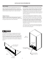
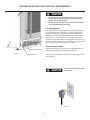
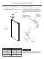
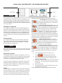
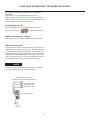
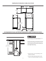
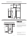
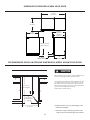
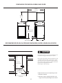
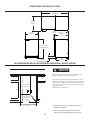
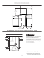
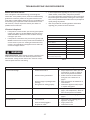
Installation
Operation
and
Maintenance
Instructions
Refrigerator Models
3CARM
6CARM
6CADM
8CARM
CONTENTS
Unpacking your refrigerator...................................................
Removing the packaging.....................................................
Warranty Registration..........................................................
Installing your refrigerator.....................................................
Selecting the location.........................................................
Cabinet Clearances..............................................................
Leveling legs........................................................................
Grounding method.................................................................
Electrical Requirements......................................................
Handle Installation ................................................................
Door Alignment ....................................................................
Using Your MicroSentry™ Refrigerator Control.....................
Starting Your Refrigerator.....................................................
Set Temperature..................................................................
Refrigerator Operation........................................................
Alarms .................................................................................
Alarm Mute.........................................................................
Turning Refrigerator Off......................................................
Remote Alarm Interface .....................................................
Dimensions For Model 3CARM Solid Door............................
Recommended Rough in Opening Dimensions
For Model 3CARM Solid Door..............................................
Dimensions For Model 3CARM Glass Door ..........................
Recommended Rough in Opening Dimensions
For Model 3CARM Glass Door...............................................
Dimensions For Model 6CARM Solid Door.............................
Recommended Rough in Opening Dimensions
For Model 6CARM Solid Door..............................................
Dimensions For Model 6CARM Glass Door............................
Recommended Rough in Opening Dimensions
For Model 6CARM Glass Door..............................................
Dimensions For Model 6CADM..............................................
Recommended Rough in Opening Dimensions
For Model 6CADM..............................................................
Dimensions For Model 8CARM Solid Door ............................
Recommended Rough in Opening Dimensions
For Model 8CARM Solid Door ...........................................
3
3
3
4
4
4
4
5
5
6
6
7
7
7
7
7
8
8
8
9
Features ................................................................................ 15
Energy Saving Tips ................................................................. 16
Care and Cleaning................................................................. 16
Troubleshooting Guide.......................................................... 17
Obtaining Service.................................................................. 17
Commercial Product Warranty.............................................. 18
Appendix A Additional MicroSentry™ Features..................... 19
Important Safety Instructions
Warnings and safety instructions appearing in this guide are not
meant to cover all possible conditions and situations that may
occur. Common sense, caution, and care must be exercised when
installing, maintaining, or operating this appliance.
Recognize Safety Symbols,
Words, and Labels.
9
10
10
11
CAUTION-Hazards or unsafe practices which could result in
personal injury or property or product damage.
11
12
12
13
WARNING-Hazards or unsafe practices which could result in
personal injury.
13
14
NOTE
14
NOTE-Important information to make a problem free installation.
2
is committed to building a quality product
in an environmentally friendly manner. Our processes are tightly
controlled and closely monitored. We have achieved certifications
in ISO 9001 for quality assurance, ISO 14001 for environmental
management, and OHSAS 18001 for occupational health and safety from Lloyd’s Register Quality Assurance.
UNPACKING YOUR REFRIGERATOR
Remove Packaging
Warranty Registration
Your refrigerator has been packed for shipment with all parts
that could be damaged by movement securely fastened. Cut
the banding material at the bottom of the carton, unfold the
carton at the bottom and remove the carton from the appliance.
Remove the plastic bag, styrofoam corner posts and any tape
holding the door closed and internal components in place. The
owners manual is shipped inside the refrigerator in a plastic bag
along with the warranty registration card.
It is important you send in your warranty registration card immediately after taking delivery of your refrigerator or you can
register online at www.agamarvel.com.
The following information will be required when registering your
unit.
Model Number
Serial Number
Date of Purchase
Dealer’s name and address
The model number and serial number can be found on the serial
plate which is located inside the cabinet on the left side near the
top.
Important
Keep your carton packaging until your refrigerator has been
thoroughly inspected and found to be in good condition. If there
is damage, the packaging will be needed as proof of damage
in transit. Afterwards please dispose of all items responsibly in
particular the plastic bags which can be a suffocation hazard.
Note to Customer
This merchandise was carefully packed and thoroughly inspected
before leaving our plant. Responsibility for its safe delivery
was assumed by the retailer upon acceptance of the shipment.
Claims for loss or damage sustained in transit must be made to
the retailer.
Help Prevent Tragedies
Child entrapment and suffocation are not problems of the past.
Junked or abandoned refrigerators are still dangerous, even if
they sit out for “just a few days”.
If you are getting rid of your old refrigerator, please follow the
instructions below to help prevent accidents.
Before you throw away your old refrigerator or freezer:
• Take off the doors or remove the drawers.
• Leave the shelves in place so children may not easily climb
inside.
DO NOT RETURN DAMAGED MERCHANDISE TO THE MANUFACTURER - FILE THE CLAIM WITH THE RETAILER.
NOTE
If the unit was shipped or has been laying on its back for any
period of time allow the refrigerator to sit upright for a period of
at least 24 hours before plugging in. This will ensure oil returns
to the compressor. Plugging the refrigerator in immediately may
cause damage to internal parts.
3
INSTALLING YOUR REFRIGERATOR
Select Location
Leveling Legs
Cabinet Clearance
To adjust the leveling legs, place the refrigerator on a solid surface and protect the floor beneath the legs to avoid scratching
the floor. With the assistance of another person, lean the refrigerator back enough to access the front leveling legs and remove
the weight. Raise or lower the legs to the required dimension
by turning the legs. Repeat this process for the rear by tilting
the refrigerator forward using caution to prevent the door from
opening. On a level surface check the refrigerator for levelness
and adjust accordingly.
Adjustable legs at the front and rear corners of the unit should
be set so the unit is firmly positioned on the floor and level from
side to side and front to back. The overall height of your Marvel
refrigerator may be adjusted from 33-3/4” (85.7cm) with the
leveling legs turned in, and up to 34-3/4” (88.3cm) with the leveling legs extended. The 80 cabinets (30” wide) have a center leg
at the rear of the cabinet that must also be used to stabilize the
cabinet. (See Figure 2).
The proper location will ensure peak performance of your appliance. We recommend a location where the unit will be out
of direct sunlight and away from heat sources. To ensure your
product performs to specifications the recommended installation
location temperature range is from 55 to 100°F (13 to 38°C).
Ventilation is required from the bottom front section of the unit.
Keep this area open and clear of any obstructions. Adjacent
cabinets and counter top can be installed around the unit as long
as the grille and door access remain unobstructed.
The front grille (toe kick) screws may be loosened and adjusted
to the desired height. When adjustment is complete tighten the
two toe kick screws. (See Figure 2).
Front Grille
Do not obstruct the front grill. The openings within the front
grill allow air to flow through the condenser heat exchanger.
Restrictions to this air flow will result in increased energy usage
and loss of cooling capacity. For this reason it is important this
area to not be obstructed and the grill openings kept clean. AGA
MARVEL does not recommend the use of custom made grills as
air flow may be restricted because of inadequate openings. (See
Figure 1).
Figure 2
Rear of unit
Access cover
removed
Front Grille, keep
this area open.
Rear leveling legs
at outside corners
Center rear leveling
leg on 30” wide units
only
Figure 1
Leveling Legs
4
GROUNDING METHOD AND ELECTRICAL REQUIREMENTS
•
•
Do not splash or spray water from a hose on the refrigerator! Doing so may cause an electrical shock, which may
result in severe injury or death.
This unit should not, under any circumstances, be installed
to an un-grounded electrical supply.
Grounding Method
This product is factory equipped with a power supply cord that
has a three-pronged, grounded plug. It must be plugged into a
mating grounding type receptacle in accordance with the National Electrical Code and applicable local codes and ordinances
(see Figure 4). If the circuit does not have a grounding type receptacle, it is the responsibility and obligation of the customer to
provide the proper power supply. The third ground prong should
not, under any circumstances, be cut or removed.
Electrical Requirements
Electrical Requirements: A 115 volt, 15 amp dedicated circuit is
required. A 3 prong grounded receptacle is required.
Toe kick (Front Grille)
Figure 3
The unit must be installed according to your local building codes
and ordinances.
Toe kick screw
Do not use an extension cord with
this appliance.
Figure 4
5
HANDLE INSTALLATION AND DOOR ALIGNMENT
Handle Installation (Solid Door Models)
Door Alignment Procedure
1. Remove the handle, (2) screws, and 5/32” allen wrench from
the bag shipped inside the cabinet.
2. Locate handle opposite the hinges and secure in place using
the (2) screws and the allen wrench. (See Figure 5).
The door should be parallel to the sides and top of the refrigerator. If alignment is necessary the door may be adjusted by
loosening the 2 screws which secure the hinge adapter brackets
on the top and bottom of the door and adjusting the door side
to side. Use a 5/32” allen wrench for this procedure. (See Figure
6 below). When finished aligning the door, tighten the screws
securely.
Screws
Handle
Remove top
hinge pin to remove the door.
Hinge adapter bracket located on the top and bottom
of the door.
9/32”
(7.1mm)
Figure 5
Right hand hinged
door shown
Figure 6
Door should be
parallel to top
and sides of
refrigerator.
Door Reversal
It is possible to reverse the door (change from right hand swing
to left hand swing or vice versa) if you wish. To do so it will be
necessary to order one of the service kits below.
Hinge Color
Door Color
Right Hand
Left Hand
Chrome
Black
42247595
42247599
Chrome
White
42247639
42247640
Black
Black
42247596
42247600
White
White
42247597
42247601
Stainless
Steel
Stainless
Steel
42247598
42247602
NOTE
For the door to close properly, it is necessary to maintain a
minimum space of 9/32” (7mm) between the door and cabinet
flange (See Figure 6). This space can be adjusted by adjusting the
top and bottom hinge adapter brackets.
6
USING YOUR MICROSENTRY™ REFRIGERATOR CONTROL
Alarm
C
Door Switch
Control
Set
NOTE
Colder
Press and Hold
Warmer
ON/OFF
Press and Hold
Figure 7
During initial startup, or anytime power is interrupted, there will
be an approximate 5 minute delay before the refrigerator starts.
During this period the controller will be assessing the temperature in the refrigerator and the display will appear erratic, this is
normal. The desired set temperature can be programmed during
this start up period.
dible alarm will sound, beeping in one (1) second intervals.
•
Door Ajar Alarm: If the door has been left
open for over five (5) minutes, the alarm will sound
and the display panel will flash “do.” The alarm will
stop once the door has been closed.
•
High and Low Temperature Alarm: If your unit
reaches an unacceptable temperature, above or below your set temperature for too long, the temperature alarm will sound in one (1) second intervals.
The display panel will flash either “hi” or “Lo” depending upon the condition. “hi” indicates a high temperature
alarm, and “Lo” indicates a low temperature alarm. How far
the temperature must deviate above or below set temperature,
and for how long the temperature must remain there before the
temperature alarm is triggered is fully customizable. See Appendix A for details on how to configure the alarm.
•
Temperature Sensor Fault: If the control
detects that the temperature sensor is not properly
functioning, an audible alarm will sound, and “E1”
will flash on the display. Please call AGA MARVEL customer service or your dealer if this error code is displayed.
•
Condenser Needs Cleaning: When the refrigerator has reached the recommended amount of run
time for a condenser cleaning, “cL” will flash on the
display as a reminder to clean the condenser. No audible alarm
is associated with the condenser clean warning. To clear the
alarm:
1) Press and quickly release the SET key 7 times.
Starting your refrigerator
The refrigerator will begin start up when initially plugged in or
when power resumes after a power outage. At this time the refrigerator will take approximately 5 minutes to begin running as
noted above. If the refrigerator has been turned off during use,
“OFF” will appear on the display. To start the refrigerator from
the “OFF” position press and hold the ON/OFF button for three
seconds.
Set temperature
To set the set temperature, press and continue to hold “SET”
button. After one second, set temperature will be displayed.
While holding “SET” button use the “WARMER” or “COLDER”
button to desired set temperature.
NOTE
NOTE: Momentarily pressing & releasing “SET” button will access
information menu of control. Refer to appendix A for information
on this feature.
Refrigerator operation
The available temperature range of the refrigerator is 1° to 7° C.
It may take up to 24 hours for your refrigerator to reach desired
temperature. This will depend on amount of contents loaded
and number of openings and closings of the door.
“cnd”
will be displayed on the screen.
While “cnd” is displayed, press and hold the SET key.
The display will show the number of weeks the condenser has been operating.
3) Continue to hold the SET key, then press and release the
ON/OFF key. The number shown on the display will be
reset to 00.
4) Release the SET key.
5) The display will return to normal operation after a few
seconds with no key presses.
See the detailed owner’s reference guide for further details.
2)
For best results allow refrigerator to “pull down” to desired set
temperature before loading. Once contents are loaded, allow
at least 48 hours for temperature to stabilize before making any
adjustments to the set temperature.
Alarms
Your MicroSentry™ refrigerator control will monitor refrigerator
function and alert you with a series of audible and visual alarms.
For all alarm and error codes, the alarm LED located in the top
left corner of the display panel will illuminate a steady amber.
For all alarm and error codes except condenser cleaning, an au-
7
USING YOUR MICROSENTRY™ REFRIGERATOR CONTROL
See the “care and cleaning” section for cleaning instructions.
Alarm Mute
Press any key to mute the audible portion of an alarm.
NOTE-This action will only mute the alarm. If the condition that
caused the alarm continues, the alarm code will continue to flash
and will sound for 20 seconds every 60 minutes.
Turning Refrigerator Off
To turn refrigerator off, press and hold “ON/OFF” button for
three (3) seconds. “OFF”
will appear on the display.
Additional MicroSentry™ Features
Refer to Appendix A for details on additional features available.
Remote Alarm Interface
The MicroSentry™ control provides the ability to monitor alarm
conditions via a set of dry relay contacts. Alarm functions that
may be monitored by the dry contacts are: door ajar, high / low
temperature, senor fault, and power failure. Note: Intentionally
turning the unit off will disable all alarm outputs on the remote interface except power failure. It is recommended that the remote
monitoring device(s) have an uninterruptible power source.
NOTE
The alarm interface follows the state of the alarms. Muting the
alarm will not change the state of the relay contacts.
Remote Alarm Connections
Maximum Contact Rating: 125-250V 5A
Orange Wire / NC
Blue Wire / COM
Yellow Wire / NO
Remote Alarm Relay
Figure 8
8
DIMENSIONS FOR MODEL 3CARM SOLID DOOR
37-1/16”
(94.13 cm)
15-7/8”
(40.34 cm)
24-19/32”
(62.34 cm)
14-7/8”
(37.78 cm)
23-9/32”
(59.13 cm)
33-3/4” to 34-3/4”
(85.7 to 88.3 cm)
3” to 4”
7.62 to 10.2cm)
21-3/16”
(53.82 cm)
RECOMMENDED ROUGH IN OPENING DIMENSIONS, MODEL 3CARM SOLID DOOR
Electrical Requirements: A 115 volt, 15 amp dedicated circuit is
required. A 3 prong grounded receptacle is required.
Power outlet can be located in the back wall behind unit. Add 1”
to depth for thickness of plug, or recess outlet 1” into the wall.
Power outlet can also be installed in adjacent cabinetry with a
cutout for routing of power cord. Follow all local building codes
when installing electrical and unit.
Product weight = 100 lbs. (45.4 kg.)
** 34” to 35”
(86.36 to 88.9cm)
*24” (61 cm)
standard cabinet
depth
* Depth dimension may vary depending on each
individual installation.
15” (38.1 cm)
** Minimum rough in opening required is to be
larger than the adjusted height of the cabinet.
9
DIMENSIONS FOR MODEL 3CARM WITH GLASS DOOR
36-15/16”
(93.83 cm)
16-19.32”
(42.14 cm)
25-7/32”
(64.06 cm)
14-7/8”
(37.78 cm)
23-9/32”
(59.13 cm)
33-3/4” to 34-3/4”
(85.7 to 88.3 cm)
3” to 4”
7.62 to 10.2cm)
21-3/16”
(53.82 cm)
RECOMMENDED ROUGH IN OPENING DIMENSIONS, MODEL 3CARM GLASS DOOR
Electrical Requirements: A 115 volt, 15 amp dedicated circuit is
required. A 3 prong grounded receptacle is required.
Power outlet can be located in the back wall behind unit. Add 1”
to depth for thickness of plug, or recess outlet 1” into the wall.
Power outlet can also be installed in adjacent cabinetry with a
cutout for routing of power cord. Follow all local building codes
when installing electrical and unit.
Product weight = 100 lbs. (45.4 kg.)
** 34” to 35”
(86.36 to 88.9cm)
*24” (61 cm)
standard cabinet
depth
* Depth dimension may vary depending on each
individual installation.
15” (38.1 cm)
** Minimum rough in opening required is to be
larger than the adjusted height of the cabinet.
10
DIMENSIONS FOR MODEL 6CARM SOLID DOOR
47-3/32”
(119.61 cm)
24-7/8”
(63.20 cm)
25-11/32”
(64.36 cm)
24-3/32”
(61.19 cm)
23-7/8”
(60.66 cm)
33-3/4” to 34-3/4”
(85.7 to 88.3 cm)
3” to 4”
7.62 to 10.2cm)
22”
(55.88 cm)
RECOMMENDED ROUGH IN OPENING DIMENSIONS, MODEL 6CARM SOLID DOOR
Electrical Requirements: A 115 volt, 15 amp dedicated circuit is
required. A 3 prong grounded receptacle is required.
Power outlet can be located in the back wall behind unit. Add
1” to depth for thickness of plug, or recess outlet 1” into the
wall. Power outlet can also be installed in adjacent cabinetry
with a cutout for routing of power cord. Follow all local building codes when installing electrical and unit.
Product weight = 130 lbs. (59.1 kg.)
** 34” to 35”
(86.36 to 88.9cm)
*24” (61 cm)
standard cabinet
depth
* Depth dimension may vary depending on each
individual installation.
24” (61 cm)
** Minimum rough in opening required is to be
larger than the adjusted height of the cabinet.
11
DIMENSIONS FOR MODEL 6CARM GLASS DOOR
46-7/8”
(119.08 cm)
25-19/32”
(65.0 cm)
26-1/32”
(66.12 cm)
24-3/32”
(61.19 cm)
23-7/8”
(60.66 cm)
33-3/4” to 34-3/4”
(85.7 to 88.3 cm)
3” to 4”
7.62 to 10.2cm)
22”
(55.88 cm)
RECOMMENDED ROUGH IN OPENING DIMENSIONS, MODEL 6CARM GLASS DOOR
Electrical Requirements: A 115 volt, 15 amp dedicated circuit
is required. A 3 prong grounded receptacle is required.
Power outlet can be located in the back wall behind unit. Add
1” to depth for thickness of plug, or recess outlet 1” into the
wall. Power outlet can also be installed in adjacent cabinetry
with a cutout for routing of power cord. Follow all local building codes when installing electrical and unit.
Product weight = 130 lbs. (59.1 kg.)
** 34” to 35”
(86.36 to 88.9cm)
*24” (61 cm)
standard cabinet
depth
* Depth dimension may vary depending on each
individual installation.
24” (61 cm)
** Minimum rough in opening required is to be
larger than the adjusted height of the cabinet.
12
DIMENSIONS FOR MODEL 6CADM
46-7/8”
(119.08 cm)
25-19/32”
(65.0 cm)
26-1/32”
(66.12 cm)
23-7/8”
(60.66 cm)
24-3/32”
(61.19 cm)
31-1/8” to 32-1/8”
(79.05 to 81.60 cm)
3” to 4”
7.62 to 10.2cm)
22”
(55.88 cm)
RECOMMENDED ROUGH IN OPENING DIMENSIONS, MODEL 6CADM
Electrical Requirements: A 115 volt, 15 amp dedicated circuit is
required. A 3 prong grounded receptacle is required.
Power outlet can be located in the back wall behind unit. Add 1” to
depth for thickness of plug, or recess outlet 1” into the wall. Power
outlet can also be installed in adjacent cabinetry with a cutout for
routing of power cord. Follow all local building codes when installing electrical and unit.
Product weight = 130 lbs. (59.1 kg.)
** 31-3/8” to 32-3/8”
(79.71 to 82.25cm)
*24” (61 cm)
standard cabinet
depth
* Depth dimension may vary depending on each
individual installation.
24” (61 cm)
** Minimum rough in opening required is to be
larger than the adjusted height of the cabinet.
13
DIMENSIONS FOR MODEL 8CARM
52-15/16”
(134.47 cm)
30-7/8”
(78.44 cm)
25-11/32”
(64.36 cm)
24-3/32”
(61.19 cm)
29-7/8”
(75.90 cm)
33-3/4” to 34-3/4”
(85.7 to 88.3 cm)
3” to 4”
7.62 to 10.2cm)
22”
(55.88 cm)
RECOMMENDED ROUGH IN OPENING DIMENSIONS, MODEL 8CARM
Electrical Requirements: A 115 volt, 15 amp dedicated circuit is
required. A 3 prong grounded receptacle is required.
Power outlet can be located in the back wall behind unit. Add 1”
to depth for thickness of plug, or recess outlet 1” into the wall.
Power outlet can also be installed in adjacent cabinetry with a
cutout for routing of power cord. Follow all local building codes
when installing electrical and unit.
Product weight = 130 lbs. (59.1 kg.)
** 34” to 35”
(86.36 to 88.9cm)
*24” (61 cm)
standard cabinet
depth
30” (76.2 cm)
* Depth dimension may vary depending on each
individual installation.
** Minimum rough in opening required is to be
larger than the adjusted height of the cabinet.
14
FEATURES
3CARM Features
Probe Port (optional)
There are three full depth adjustable shelves for flexibility of content storage. The shelves can move up or down to accommodate
various content sizes. To adjust the shelves, simply lift up and pull
forward.
The optional probe port is a hole from the inside to the outside
of the unit, which could be located on the top, side, or back of
the unit. After inserting your wires or probe, seal the hole tightly
with caulk, putty, foam, etc. for proper operation.
6CARM and 8CARM Features
Glass Door (optional)
There are two adjustable shelves for flexibility of content storage.
The shelves can move up or down to accommodate various content sizes. The lower shelf pulls straight out. The top shelf is fixed
in place with plastic clips in the rear.
The optional glass door gives you the ability to see your contents
without opening the door.
Lock and Key (optional)
The optional lock and key allow you to lock and store contents to
prevent others from tampering with it.
Door Shelves 6CARM and 8CARM
To maximize storage efficiency, three door shelves are included to
store a variety of contents.
Product Temperature versus Air Temperature
Air temperature moves up and down with door openings and
compressor run and off cycles. Air has little thermal mass and
therefore changes temperature relatively quickly as the unit
cycles on and off. Stored products have much higher thermal
mass so their temperatures change much slower. While air temperature may change 5 to 10 degrees C between run and off
cycles, stored product temperature typically changes less than 2
degrees C due to their thermal mass. Always measure product
temperature, not air temperature, to determine if the products
being stored are at the proper temperature.
Bottom Shelf Bar 6CARM and 8CARM
A bottom shelf bar is included to prevent contents from falling
forward.
6CADM Features
Flat door liner.
Two pull out shelves with safety stops.
One stationary shelf that can accommodate tall contents.
15
ENERGY SAVING TIPS AND CARE AND CLEANING
Condenser
The following suggestions will minimize the cost of operating
your refrigeration appliance.
1. Do not install your appliance next to a hot appliance, (ovens,
glassware washers, etc.). heating air duct, or other heat
sources.
2. Install product out of direct sunlight.
3. Ensure the toe grille vents at front of unit beneath door are
not obstructed and kept clean to allow ventilation for the
refrigeration system to expel heat.
4. Plug your appliance into a dedicated power circuit. (Not
shared with other appliances).
5. When initially loading your new product, or whenever large
quantities of warm contents are placed within refrigerated
storage compartment, minimize door openings for the next
12 hours to allow contents to pull down to compartment set
temperature.
6. Maintaining a relatively full storage compartment will require less appliance run time than an empty compartment.
7. Ensure door closing is not obstructed by contents stored in
your appliance.
8. Allow hot items to reach room temperature before placing
in product.
9. Minimize door openings and duration of door openings.
10. Use the warmest temperature control set-temperature that
provides the proper storage for your stored contents.
11. Set the control to the “off” position if cleaning the unit requires the door to be open for an extended period of time.
12. Annually clean condenser heat exchange coil located in
machine compartment underneath unit, (see “Care and
cleaning” page 16).
The condenser underneath the cabinet does not require frequent cleaning; however, satisfactory cooling depends on adequate ventilation over this heat exchanger. It is recommended
to annually clean the condenser by vacuuming and brushing.
To access the condenser, the unit must be pulled out from the
installation, and the lower machine compartment access cover
removed.
Disconnect the power cord before cleaning the condenser.
Be sure that nothing obstructs the required air flow openings
in front of the cabinet. At least once or twice a year, brush or
vacuum lint and dirt from the front grille area (see page 4).
Cabinet
The painted cabinet can be washed with mild soap and water and
thoroughly rinsed with clear water. NEVER use abrasive scouring
cleaners.
Interior
Wash interior compartment with mild soap and water. DO NOT
use an abrasive cleaner, solvent, polish cleaner or undiluted detergent.
Glass Door (optional)
Use a glass cleaner or mild soap and water and soft cloth to clean
the glass door model. DO NOT use any abrasive cleaners.
Door Gasket
The vinyl gasket may be cleaned with mild soap and water, a baking soda solution or a mild scouring powder.
In the Event of a Power Failure
Minimize the number of door openings to prevent a gradual rise
in temperature while the power is off.
NOTE: If a power interruption occurs, the unit may take five (5) to
ten (10) minutes to restart.
16
TROUBLESHOOTING YOUR REFRIGERATOR
•
Before You Call for Service
If the unit appears to be malfunctioning, read through this
manual first. If the problem persists, check the troubleshooting
guide below. Locate the problem in the guide and refer to the
cause and its remedy before calling for service. The problem may
be something very simple that can be solved without a service
call. However, it may be required to contact your dealer or a
qualified service technician.
In all correspondence regarding service, be sure to give the
model number, serial number, and proof of purchase.
Try to have information or description of nature of the problem, how long the unit has been running, the room temperature, and any additional information that may be helpful in
quickly solving the problem.
Table A is provided for recording pertinent information
regarding your product for future reference.
•
•
If Service is Required:
•
•
If the product is within the first year warranty period please
contact your dealer or call AGA MARVEL Customer Service
at 800.223.3900 for directions on how to obtain warranty
coverage in your area.
If the product is outside the first year warranty period, AGA
MARVEL Customer Service can provide recommendations of
service centers in your area. A listing of authorized service
centers is also available at www.agamarvel.com under the
service and support section.
For Your Records
Date of Purchase
Dealer’s name
Dealer’s Address
Dealer’s City
Dealer’s State
Dealer’s Zip Code
Appliance Serial Number
Appliance Model Number
Electrocution Hazard - Never attempt to repair or perform maintenance on the unit until the main electrical power has been
disconnected. Turning the unit control “OFF” does not remove
electrical power from the units wiring.
Problem
Unit not cold enough.
Date Warranty Card Sent (Must be
within 10 days of purchase).
Table A
Possible Cause
Remedy
•
Control set too warm.
•
•
Airflow to front grille blocked.
•
•
•
•
Excessive usage or prolonged door
openings.
Door gasket not sealing properly.
Unit too cold.
•
Control set too cold.
•
Adjust temperature warmer. (See
page 7, “set temperature”). Allow 24
hours for temperature to stabilize.
Noise or Vibration.
•
Unit not level.
•
Level unit, see “Leveling Legs” on
page 4.
Unit will not run.
•
Unit turned off.
•
•
•
Power cord not plugged in.
No power at outlet.
•
•
Turn unit on. See “Starting your refrigerator” on page 7.
Plug in power cord.
Check house circuit.
17
•
Adjust temperature colder. (See “Set
temperature” on page 7). Allow 24
hours for temperature to stabilize.
Airflow must not be obstructed to
front grille. See “clearances” on
page 4.
Allow temperature to stabilize for at
least 24 hours.
Check door alignment and/or adjust
or replace door gasket.
COMMERCIAL PRODUCT WARRANTY
Entire Product - One Year Parts and Labor Warranty
AGA MARVEL warrants to the original purchaser that it will supply all necessary parts and labor to repair or replace in the end
user’s establishment, any component which is found by an authorized representative of AGA MARVEL to be defective in materials
or workmanship, subject to the conditions and exclusions stated
below, for a period of one year from the date of purchase by the
end user.
Refrigeration System - Additional Second Through Fifth Year
Parts Only Warranty
During the four years following expiration of the one year limited
warranty, AGA MARVEL warrants to the original purchaser that
it will supply replacement parts for the hermetically sealed refrigeration system which consists of the compressor, evaporator,
condenser, drier, and connecting tubing that are found to be defective in workmanship or materials. Other parts, labor costs, and
freight charges are the responsibility of the end user.
If AGA MARVEL is unable to repair or replace the defective product or component, AGA MARVEL shall issue a credit to the buyer
for all or part of the purchase price, as AGA MARVEL shall determine. The repair, replacement, or payment in the manner described above shall be the sole and exclusive remedy of buyer for
a breach of this warranty.
Buyer must give written notice of any alleged defect in the product to AGA MARVEL within 30 days after discovery of the defect
by buyer. If notice is not given within such period, any claim for
breach of warranty shall be conclusively deemed to have been
waived, and AGA MARVEL shall not be liable under these warranties. AGA MARVEL or its agents shall be entitled to examine
the product. AGA MARVEL shall have the option of requiring the
return of the defective component, transportation prepaid, to establish the claim. The acceptance by AGA MARVEL of any component returned shall not be deemed an admission that the product
is defective or in breach of any warranty and, if AGA MARVEL determines that the product is not defective, the component shall
be reshipped to the buyer at the buyer’s expense. No component
will be returned to AGA MARVEL without its prior consent.
The above warranties do not cover:
•
•
•
•
Shipping costs of replacement parts or returned defective
parts.
Customer education or instructions on how to use the refrigerator/freezer.
Any content loss, or incidental or consequential damage or
loss due to product failure.
Removal or installation.
Nor do the above warranties cover failure of this product or its
components due to:
•
•
•
•
Transportation, damage sustained in transit, or subsequent
damages.
Use in hostile environments or use for storage of contents
hostile to the product.
Improper installation, misuse, abuse, accident, or alteration,
use on wiring not conforming to electrical codes, low voltages, failure to provide necessary maintenance, or other unreasonable use.
Parts or service not supplied or designated by AGA MARVEL.
The above warranties also do not apply if:
•
•
The original bill of sale, deliver date, or serial number cannot
be verified.
The refrigeration equipment is not in the possession of the
original end use purchaser.
The warranties set forth herein are the only warranties extended by AGA MARVEL and are in lieu of all warranties, express,
implied, statutory, or otherwise. In particular, AGA MARVEL
makes no warranty of merchantability or fitness for a particular
purpose.
AGA MARVEL’s liability for any defect in the product shall not exceed the purchase price of the product. AGA MARVEL shall have
no liability for consequential damages of any kind whatsoever,
including, but not limited to, personal injury, property damage,
lost profits, or other economic injury due to any defect in the
product.
No person, firm, or corporation is authorized to modify, expand,
or extend these warranties, to waive any of the limitations or exclusions, or to make any other warranty or assume any other obligation for AGA MARVEL. These warranties apply only to products
used in any of the fifty states of the United States and the District
of Columbia.
To obtain performance of this warranty, report any defects to:
1260 E. VanDeinse St.
Greenville MI 48838
Toll-Free: 800.223.3900
18
APPENDIX A, ADDITIONAL MICROSENTRY™ FEATURES
Information Menu / Lockout Key
To access the information menu, press the SET key, and immediately release it.
In the information menu, a 2 or 3 digit code will be displayed
representing each entry in the information menu. The first code
displayed will be t1. With each sequential press and release of
the SET key, the following codes will appear in this order: t1, thi,
tLo, Ahi, ALo, AdL, cnd, and Loc.
To view the value of each code, press and hold the SET key after
the desired code is displayed. Additionally, the WARMER and
COLDER keys may be used to scroll through the menu. To exit
the information menu, press the ON/OFF key, or wait for several
seconds with no key presses.
1) Current Interior Temperature (tI): While tl is
shown on the screen press and hold the “SET”
key to display the current interior temperature.
2) Maximum Stored Temperature (thi): While
thi is shown on the screen, press and hold the
“SET” key to display the maximum recorded
temperature. The temperature is updated every 5 minutes. To
reset the maximum temperature; continue to hold the SET key,
then press and release the ON/OFF key to reset the maximum
temperature. The maximum temperature will be reset to the
current compartment temperature.
It is recommended that thi be reset after the initial pull-down
(24 hours after power on) to clear any residual values.
3) Minimum Stored Temperature (tLO): While tLo
is shown on the screen, press and hold the “SET”
key to display the minimum recorded temperature. The temperature is updated every 5 minutes. Continue to
hold the SET key then, press and release the ON/OFF key to reset
the minimum temperature. The minimum temperature will
be reset to the current compartment temperature. It is recommended that tLo be reset after the initial pull down (24 hours
after power on) to clear any residual values.
4) Relative High Temperature Alarm (Ahi): The
number of degrees C warmer relative to the
set temperature that will initiate a high temperature alarm. Once the compartment temperature exceeds
the high temperature alarm value, the control will delay AdL
minutes before initiating the alarm. See Alarm Delay section
below for instructions to set alarm delay. While Ahi is displayed
on the screen, press and hold SET key to view the value of Ahi.
To adjust the value, continue to hold SET then use the WARMER
and COLDER keys until the desired value is shown on the screen.
Release the SET key to confirm the new setting. Factory default
value for Ahi is 2.0°C.
Note: Setting Ahi = 0 will disable the high temperature alarm.
The control’s 2°C Hysteresis value is automatically added to Ahi.
For example, let set temperature = 4°C, and Ahi = 3. The high
temperature alarm will activate at 9°C = (4 [set temperature] + 3
[Ahi] + 2 [hysteresis])
5) Relative Low Temperature Alarm (ALO): The
number of degrees C colder relative to set tem
perature that will initiate a low temperature
alarm. Once the compartment temperature exceeds the low
temperature alarm value, the control will delay AdL minutes
before initiating the alarm. See Alarm Delay section below for
instructions to set alarm delay. While ALo is displayed on the
screen, press and hold SET key to view the value of ALo. To
adjust the value, continue to hold SET then use the WARMER
and COLDER keys until the desired value is shown on the screen.
Release the SET key to confirm the new setting. Factory default
value for ALo is -2.0°C.
Note: Setting ALo = 0 will disable the low temperature alarm.
No hysteresis value is added to ALo. For example, let set temperature = 4°C, and ALo = -3. The low temperature alarm will
activates at 1°C = (4 [set temperature] + -3 [ALo])
6) Alarm Delay (AdL): The number of minutes the
compartment temperature must be outside the
range specified by Ahi and ALo before a temperature alarm activates. While AdL is shown on the screen, press
and hold SET key to view the value of AdL. To adjust the value,
continue to hold SET then use the WARMER and COLDER keys
until the desired value is shown on the screen. Release SET key
to confirm the new setting. Factory default value for AdL is 60
minutes.
7) Total Operating Time of the Condenser Since
the Last Cleaning (cnd): The operating time of
the condenser since the last cleaning. The control
monitors the operating time of the condenser fan to determine
when the condenser is in need of being cleaned. While cnd is
displayed on the screen, press and hold SET key to view the value
of cnd. The value shown is the number of weeks the condenser
has been operating. To reset cnd, continue to hold the SET key
then press and release the ON/OFF key.
When the control recommends the condenser be cleaned, a
reminder will be displayed on the screen (see Alarm Codes.) To
clear the alarm code, reset the value in cnd following the instructions printed above.
8) Keypad Lockout Feature (Loc): This feature is
used to prevent incidental changes to the set
temperature, or accidentally turning the unit off.
While Loc is displayed on the screen, press and hold the SET key.
If “No”
is displayed, Lockout feature is off, and all
keys are enabled. If “Yes”
is displayed, Lockout feature is ON. The ability to turn the unit on and off, as well as the
ability to adjust set temperature will be disabled. To change the
keypad lockout setting, continue to hold the SET key, then use
the WARMER and COLDER keys to set the desired value.
19
www.agamarvel.com
1260 E. VanDeinse St.
Greenville MI 48838
800.223.3900
41011808-EN Rev G
10/28/11
All specifications and product designs subject to change without notice. Such revisions do not entitle the
buyer to corresponding changes, improvements, additions, replacements or compensation for previously
purchased products.