1
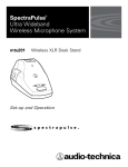
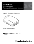
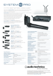
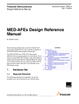
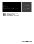
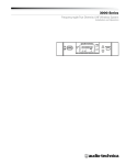
SpectraPulse™
Ultra Wideband
Wireless Microphone System
drm141
aci707
mtu101
cei007
Digital Receiver Module
Audio Control Interface
Microphone Transmitter Unit
Charging /Encryption Interface
Set-up and Operation
2
This device complies with part 15 of the FCC Rules. Operation is subject to the condition that this device does not cause harmful interference.
This device complies with INDUSTRY CANADA R.S.S. 210, en conformité avec IC: RSS-210/CNR210.
Operation is subject to the following conditions: 1) This device may not cause harmful interference and 2) this device must accept any interference
received, including interference which may cause undesired operation. Changes or modifications not expressly approved by Audio-Technica could
void your authority to operate this equipment.
Note: This equipment has been tested and found to comply with the limits for a Class A digital device, pursuant to Part 15 of the
FCC Rules. These limits are designed to provide reasonable protection against harmful interference when the equipment is operated
in a commercial environment. This equipment generates, uses, and can radiate radio frequency energy and, if not installed and used
in accordance with the instruction manual, may cause harmful interference to radio communications. Operation of this equipment
in a residential area is unlikely to cause harmful interference. However, if the equipment does cause harmful interference, the user
will be required to correct the interference at own expense.
CAUTION! Electrical shock can result from removal of SpectraPulse™ components' covers. Refer servicing to qualified service personnel.
No user-serviceable parts inside. Do not expose to rain or moisture.
The circuits inside the SpectraPulse™ components have been precisely adjusted for optimum performance and compliance with federal
regulations. Do not attempt to open the drm141 Digital Receiver Module (main assembly), aci707 Audio Control Interface, mtu101 Boundary
Microphone Transmitter or cei007 Charger Encryption Interface. To do so will void the warranty, and may cause improper operation.
Notice to individuals with implanted cardiac pacemakers or AICD devices:
Any source of RF (radio frequency) energy may interfere with normal functioning of the implanted device. All wireless microphones have lowpower transmitters (less than 0.05 watts output) which are unlikely to cause difficulty, especially if they are at least a few inches away. Note
also that any medical-device disruption will cease when the RF transmitting source is turned off. Please contact your physician or
medical-device provider if you have any questions, or experience any problems with the use of this or any other RF equipment.
Please note that your SpectraPulse™ system operates in a frequency band in a way which may make its use subject to certain FCC and other
regulatory agency restrictions and licensing requirements. No changes or modifications may be made to this equipment except by the
expressly approved responsible party for compliance. Changes or modifications could void the user's authority to operate the equipment, and
will also void Audio-Technica warranty coverage. For further information, Please contact your local office of the FCC as applicable.
Battery precautions
• Each mtu101 Boundary Microphone Transmitter is powered by 2 AA batteries; alkaline batteries are included,
but rechargeable SANYO brand 2700 mAH NiMH AA batteries are recommended.
• Each cei007 Charging/Encryption Interface includes 14 rechargeable SANYO brand NiMH AA batteries.
Note: Other models of NiMH batteries may work, but the cei007 and the mtu101 are optimized for use with SANYO 2700 mAH NiMH
AA batteries.
• SpectraPulse™ cei007 Charging/Encryption Interface is intended only for use of mtu101 Boundary Microphone Transmitters equipped with
rechargeable AA Nickel Metal Hydride (NiMH) batteries. Do not use the charging station for products other than the Audio-Technica
SpectraPulse™ system. WARNING: Do not use the cei007 Charging/Encryption Interface to charge batteries of other types besides
NiMH or damage may result.
• Rechargeable batteries must be charged before initial use or after prolonged non-use.
• When recharging, follow instructions in this manual.
• When inserting batteries into the mtu101, observe correct polarity as marked.
• Do not use a leaking battery. If battery leakage occurs, avoid contact with skin. If contact occurs, immediately wash thoroughly with soap
and water. If battery leakage comes into contact with your eyes, immediately flush with water and seek medical attention.
• Do not expose the batteries to fire. Do not heat, deform, solder, disassemble or modify the batteries.
• Do not peel off or damage the outer tube of a battery.
• Do not use these batteries together with dry cells, other types of batteries, new and old batteries together, or batteries with different
charge levels.
Note: This SpectraPulse™ system is approved for indoor use only.
3
Contents
SpectraPulse System Features
SpectraPulse UWB Wireless Microphone System Components
SpectraPulse System Installation & Operation
drm141 Digital Receiver Module
aci707 Audio Control Interface
mtu101 Boundary Microphone Transmitter Unit
cei007 Charging/Encryption Interface
drm141 Digital Receiver Module Controls and Functions
aci707 Audio Control Interface Front Panel Controls and Functions
aci707 Audio Control Interface Rear Panel Controls and Functions
mtu101 Boundary Microphone Transmitter Controls and Functions
cei007 Charging/Encryption Interface Controls
Specifications
3
4
5
5
5
6
7
8
10
11
13
14
15
System Features
• Ultra Wideband (UWB) wireless operation
Delivers clear, intelligible audio without the performance and
set-up issues associated with conventional RF wireless
microphone systems.
• Easy to set up and operate
Designed for quick, intuitive setup and user-friendly operation.
• Interference-free performance
Very few RF devices are approved to operate in the frequencies
where the SpectraPulse™ UWB wireless microphone system operates.
• No problems in crowded RF environments
Bypasses the increasingly congested UHF, VHF and 2.4GHz
frequency bands; ideal for use in areas with high RF congestion.
• No frequency hunting or coordination
14 simultaneous channels operate with no frequency coordination
required. Channel selection is quick and easy.
• Immunity to multipath interference
Offers extremely reliable performance; no dropouts or sputters.
• Inherent security
UWB data is transmitted in extremely short-duration pulses sent
in a timed sequence over a wide frequency spectrum. To decode
the pulses, the Digital Receiver Module must know exactly
when, where and how to listen. This makes SpectraPulse™
inherently secure.
• Encryption available
Optional encryption package meets NIST-approved AES 128-bit
encryption standard developed by the U.S. government for
securing sensitive material.
• Excellent audio quality
Digital signal requires no compression; imperceptible latency;
microphone muting is silent.
• Universal interface
Connects with teleconference systems, videoconference
systems, PA/local sound systems, archive recording and
logging systems.
• Contact closure input/output (on Audio Control Interface)
Provides control interface with external devices.
• Flexible performance
Soft-touch button on boundary microphone/transmitter is
configurable for push-to-talk, push-to-mute, and toggle operation.
• Minimal Rack Space Required
7 channels in 1 rack space, 14 channels in 2 rack spaces.
• Optional rechargeable batteries and charging/encryption
station
Extended mAH rechargeable AA NiMH batteries (preferred for
best battery life performance) are included with optional
cei007Charging /Encryption Interface.
4
SpectraPulse™ Components
and Included Accessories
The SpectraPulse™ UWB wireless microphone system consists of four components: the drm141 Digital Receiver Module, designed for ceilingor wall-mount; the aci707 Audio Control Interface, which is designed to be rack-mounted; the mtu101 Boundary Microphone/Transmitter;
and the cei007 Charging/Encryption Interface (optional).
drm141 Digital Receiver Module
• 25' shielded Category 5 (Cat 5) cable with RJ45 connectors for
use between aci707 and drm141
• Ferrite bead (for use with user-supplied Cat 5 cable)
aci707 Audio Control Interface
• IEC power cable
• Seven 3-pin Phoenix-type connectors (audio outputs)
• Two 8-pin Phoenix-type connectors (control i/o connections)
• 8" shielded Cat 5 cable with RJ45 connectors (for linking two
aci707 units together)
mtu101 Boundary Microphone Transmitter
• AA Alkaline batteries (2 batteries per transmitter)
cei007 Charging Encryption Interface
• Power supply
• Rechargeable AA NiMH batteries (14 batteries)
5
System Installation & Operation
Thank you for purchasing the Audio-Technica SpectraPulse™ UWB wireless microphone
system. It is our hope that the system will bring you years of trouble-free performance.
Please follow the information contained in this manual closely, as it will assist you in using
your equipment effectively.
drm141 Digital Receiver Module
The drm141 Digital Receiver Module functions as both the UWB receiver and antenna for 14
channels. It consists of three assembly components that can be used for different mounting
requirements: the main assembly, the front bezel, and the plastic rear housing. Note: Do not
disassemble the main assembly. Doing so may void your warranty and possibly void the
authority to operate the unit.
Note: Never plug or unplug the shielded Cat 5 cable to or from the drm141 if the cable is
already connected to the aci707 and the power is on. Make certain aci707 power is off
before connecting or disconnecting the cable.
1. Placement – Locate the drm141 within 300 feet of the aci707. The drm141 Digital Receiver
Module should be mounted to a wall or ceiling or set on a flat surface. Ideal placement is
high, with clear line of sight to all the microphone/transmitter units. Note: The drm141 must
be in the same room as the microphone/transmitters.
2. To flush-mount the drm141 inside a 3-gang, 2-1/2" deep electrical box, see Mounting to a
3-gang electrical box, page 9.)
3. For more portable or surface applications, the unit is shipped assembled in the plastic rear
housing, which provides key-hole slots on the back for mounting on a wall; or the unit may
be placed on a flat surface. (See Mounting in the supplied plastic rear housing, page 9.)
4. Connect the shielded Cat 5 cable (supplied) to the RJ45 connector on the rear of the drm141.
The other end of this Cat 5 cable will be connected to the “Link In” RJ45 connector on the
rear of the aci707 Audio Control Interface (with aci707 power off). (See Link-Out and Link-In
RJ45 Connectors on page 11.) Note: A 25' shielded Cat 5 cable is supplied with the
system; you may supply your own shielded Cat 5 cable for lengths up to 300'. If you
use your own CAT 5 cable, attach the provided ferrite bead to the cable as close to the
drm141 as feasible. Do not plug cable from the aci707 into an Ethernet port.
aci707 Audio Control Interface
The SpectraPulse™ aci707 Audio Control Interface provides the connection point to the audio
system, and a control platform to set the system functions. It also provides control interface
points (contact closures) for interface to external equipment. These closures can be used to
activate lights, control cameras, etc.
1. Placement – Locate the aci707 Audio Control Interface within 300 feet of the drm141 Digital
Receiver Module. Note: The aci707 does not have to be in the same room as the drm141.
2. Plug the aci707 Audio Control Interface into the AC power source. (See Power cord, page 11.)
Note: Make certain you do not turn on the power until after all the system connections
are made.
3. With the power off, connect the shielded Cat 5 cable exiting the drm141 to the “Link In”
RJ45 input connector on the rear of the aci707. Note: Do not plug RJ45 connector or Cat
5 cable into the aci707 with the power on. Do not plug cable from the aci707 into an
Ethernet port. (See Link-Out and Link-In RJ45 Connectors on page 11.)
If a second aci707 is used, connect the included 8" shielded Cat 5 cable from the Link-Out
on the first aci707 to the Link-In in the second aci707.
(contined on page 6)
6
aci707 Audio Control Interface (continued)
4. For each audio channel you will use (this equals the number of microphone transmitters in
use), connect a cable to the corresponding Audio Output on the rear of the aci707. Each
aci707 provides seven channels of audio output for connection to your external equipment
(mixers, recording devices, teleconferencing equipment). (See Audio Outputs, page 11.)
5. Preliminary factory setup of DIP Switches is as follows:
• 1&2: Toggle mode (Mic/transmitter’s soft-touch mute button is in touch on/touch off mode.)
• 3: Local control (Mic/transmitter’s soft-touch button controls audio output.)
• 4: Channels 1-7 (Assign channels 1 through 7 to mic/transmitters.)
• 5: Active mode (aci707 will send data back to mic/transmitters.)
• 6: Mic level output (Low-level output.)
To change these settings, see DIP Switch Configuration Settings on page 12.
6. Press the power button on the front panel of the aci707. Confirm that the blue power LED
comes on. With switches in factory setup positions (see number 5 above), the mic level
output LED will also be illuminated as will the red Mute LEDs for channels 1-7. (Press each
mic/transmitter’s touch button to unmute.)
mtu101 Boundary Microphone Transmitter Unit
The mtu101 Boundary Microphone Transmitter is equipped with a soft-touch button that can be
programmed for push-to-talk, push-to-mute, or toggle operation; on/off switch; channel address
selector; LEDs indicating power/mute and link status; low-battery warning and more.
1. Insert 2 fully charged rechargeable NiMH AA batteries or 2 fresh AA 1.5V alkaline batteries
in each mtu101 Boundary Microphone Transmitter. (See Battery Selection & Battery
Installation, page 13.) Note: Be certain the NiMH batteries are fully charged: see How to
use the cei007 as a recharging station, page 7.
2. Select a unique channel address on the bottom of each mtu101 Boundary Microphone
Transmitter. (1-7 for the first aci707 audio control interface unit used; 8-14 for the second
aci707 unit). (See Channel Address Selection, page 13.)
3. Turn on the power switch on the bottom of each boundary microphone. The Power LED
(A-T logo) on the top of the boundary microphone transmitter will glow blue. (See Power
On/Power Off, page 13.)
4. Confirm link status. If the boundary microphone transmitter is properly linked, the Link LED
will glow blue and the top green light on the corresponding aci707 channel will light. (See Link
LED, page 13.)
5. Confirm mute/live audio status. When the audio is on, the elliptical Live Audio LEDs glow
blue. To change mute status, depress the microphone/transmitter's soft-touch button. (See
Audio Mute LED, page 14.) Note: Button function is programmable. See DIP Switches
1 & 2 control microphone/transmitter button function, page 12.
6. Confirm battery status. Low battery is indicated by blinking power light (top logo portion).
(See Low Battery Warning, page 13.)
7. With the aci707 on and connected as desired, the drm141 connected, and the boundary
microphone transmitters on, speak into each microphone and verify audio operation. Set the
input levels on your connected equipment as needed. (If connected equipment requires linelevel inputs, set DIP Switch #6 to line level as described in DIP Switch 6 selects Line or Mic
level on page 12.) You are now set to use the system.
7
cei007 Charging/Encryption Interface
The cei007 Charging/Encryption Interface has two functions:
The cei007 is a 7-bay charger for SpectraPulse™ mtu101 Boundary Microphone Transmitters
using the supplied rechargeable AA Nickel Metal Hydride (NiMH) batteries. It is able to charge
up to seven mtu101 units (14 AA NiMH batteries) either separately or together in about 6 hours.
LEDs show charging status at all times.
The upper-most bay of the cei007 also functions as an encryption station for SpectraPulse™
mtu101 Boundary Microphone Transmitters (in conjunction with optional SpectraPulse™ System
Encryption Software – available separately-see page 14). SpectraPulse™ encryption meets NISTapproved AES 128-bit encryption standard developed by the U.S. government for securing
sensitive material. (See the SpectraPulse™ sep128 Encryption Manual for instructions on how to
encrypt the SpectraPulse™ UWB wireless microphone system.)
How to use the cei007 as a recharging station
1. Plug the DC cable from the included wall-adapter power supply into the rear of the cei007
unit; plug the other end of the power cord into a standard wall outlet. (See cei007 Power
Cord, page 14.)
2. Turn the cei007 unit on. (See cei007 On/Off Switch, page 14.) All LEDs will illuminate for
approximately 2 seconds.
3. Make certain that the mtu101 Boundary Microphone Transmitters you will be recharging are
equipped with rechargeable AA NiMH batteries (included with cei007 unit) that are correctly
installed. WARNING: Do not use the cei007 Charging/Encryption Interface to charge
batteries of other types besides NiMH or damage may result. If an mtu101 with alkaline
batteries is inserted for charging, the green and red LEDs will flash simultaneously as a
warning. (See mtu101 Battery Installation, page 13.)
4. Turn the mtu101 Boundary Microphone Transmitters off. (If the mtu101 units are on, they will
not recharge properly and the green and red LEDs will flash simultaneously as a warning.)
(See mtu101 Power On/Off, page 13.)
5. Place mtu101 units in charging bays as illustrated at right.
6. Confirm that the red Charging LEDs (on the cei007) are illuminated.
7. When green Full-Charge LEDs (on the cei007) come on, the batteries are fully charged and
ready for use. You may use them immediately, or leave the mtu101 units in the recharging
station until next needed.
Note: The charger does not use a “trickle charge” current to maintain full battery. If you
leave fully charged mtu101 units in the charger for a long period, some of the charge
may be depleted. In this case (to ensure that the batteries are completely charged for
maximum operating time), turn the cei007 unit off and on again and wait until the
green Full-Charge LEDs are again illuminated before removing the microphones from
the charging bays.
8
drm141 Digital Receiver Module
Controls & Functions
4
1
drm141 assembled as shipped
2
3
1 Unlike a typical wireless system that uses a separate receiver for each channel, the SpectraPulse™
UWB Wireless Microphone System uses a single Digital Receiver Module for 14 channels. The
drm141 functions as both the UWB receiver and antenna. It consists of three basic assembly
components that can be used for different mounting requirements: the main assembly, the front
bezel, and the plastic rear housing.
Note: The drm141 must be located in the same room in which the system will be operating.
Main Assembly
2 The main assembly consists of a white antenna plate and a metal-shielded back box that houses
electronics. Note: Do not disassemble the main assembly. Doing so may void your warranty
and possibly void the authority to operate the unit.
Front Bezel
3 This component “snaps” on to the front of the antenna plate, providing a finished appearance; it
fits with either the Plastic Rear Housing or installations into electrical boxes. (See Mounting in the
Supplied Plastic Rear Housing, or Mounting to a 3-Gang Electrical Box, page 9.)
Plastic Rear Housing 4 This housing is provided for use in applications where the antenna unit cannot be installed directly
into a standard 3-gang electrical box. The housing provides key-hole slots on the back for mounting
on a wall, or the unit may be placed on a flat surface. The main assembly is mounted directly to
this housing with 6 screws. (See Mounting in the supplied plastic rear housing, page 9.)
(rear view)
(contined on page 9)
9
drm141 Digital Receiver Module Controls & Functions (continued)
Note: The unit is shipped assembled in the supplied plastic rear housing. Before installing
the drm141 in a 3-gang electrical box, you must first remove it from the supplied plastic
rear housing, as follows:
• Unscrew (2) #6 x 1/2" screws that secure the front bezel onto the antenna and box.
(Use #2 Philips screwdriver bit.) (A)
• Use slots on the sides of the bezel to gently pry the front bezel off. (B)
• Unscrew (6) #6 x 3/8" screws from the mounting holes (3 at top, 3 at bottom).
(Use #2 Philips screwdriver bit.)
• Remove the main assembly from the plastic rear housing.
Mounting to a 3-gang Electrical Box
A
To flush-mount the Main Assembly in a 3 gang, 2-1/2" deep electrical box (RACO model 692 or 686
or equivalent):
• Locate the shielded Cat 5 cable exiting the 3-gang box (RACO model 692 or 686 or equivalent)
and connect it to the drm141 through the RJ45 connector opening on the back of the metal
shield box.
• Insert the drm141 Main Assembly into the 3-gang box.
• Attach with (6) #6 x 3/8" screws (included) through the Main Assembly mounting holes (3 at
top and 3 at bottom) that line up with standard 3-gang mounting screw receptacles.
• After the assembly is mounted in the box, snap the front bezel onto the white antenna plate.
To remove the bezel, gently pry it off with a screwdriver or coin at the slots on the sides of
the bezel. (Bezel may be painted to match room décor.)
B
Note: The drm141 is shipped assembled in the plastic rear housing. If you have removed it
from this supplied housing and need to reassemble the unit, use the following steps:
• Insert the main assembly into the plastic rear housing and make certain that the RJ45
connector openings line up.
• Attach with (6) #6 x 3/8" screws (included) through the mounting holes (3 at top, 3 at bottom).
• Snap the front bezel onto the antenna and box. Secure the front bezel with (2) #6 x 1/2"
screws (included).
• Connect a shielded Cat 5 cable to the RJ45 connector openings on the back, and feed the
shielded Cat 5 cable out via one of the cable channels on the back of the plastic rear housing
before mounting on the wall. Note: A 25' shielded Cat 5 cable is supplied with the
system; you may supply your own shielded Cat 5 cable for lengths up to 300'. If you
use your own CAT 5 cable, attach the provided ferrite bead to the cable as close to
the drm141 as feasible.
• This entire unit can be placed on a flat surface or hung via keyhole slots on a wall.
Mounting in the supplied plastic rear housing
When the drm141 is mounted as you desire, and the shielded Cat 5 cable is exiting the rear of the
assembly, plug the other end of the Cat 5 cable into the “Link In” RJ45 connector on the rear of
the aci707 Audio Control Interface (with aci707 power off).
RJ45 Connector
Note: Never plug or unplug the shielded Cat 5 cable to or from the drm141 if the cable is
already connected to the aci707 and the power is on. Make certain aci707 power is off before
connecting or disconnecting the cable.
10
aci707 Audio Control Interface Front Panel
Controls and Functions
1
2
4
3
5
Power Switch 1 Press this button in to turn the unit on; the aci707 Audio Control Interface LEDs will light. Press
again to turn the unit off.
RS232 Connector for Encryption 2 Use for optional encryption. (See SpectraPulse™ sep128 Encryption Owners Manual.)
Encryption LED (Red) 3 When the Encryption LED is illuminated, the system is operating with encryption (the encryption
key has been set). (See SpectraPulse™ sep128 Encryption Owners Manual for instructions on how
to set the encryption key.)
Line/Mic LEDs (Yellow/Orange) 4 Indicates whether the unit is operating with Line (yellow) or Mic (orange) level output.
LED indicators 5 There are seven vertical columns and four horizontal rows of LED indicators. The seven vertical
LED columns correspond to the seven microphone/transmitters, numbered 1 - 7 (or 8 - 14 if this
is the second aci707 unit in use.) One vertical column is designated for each of 7
microphone/transmitters.
Four horizontal rows of LEDs indicate the following information:
LINK (green LED):
The “Link” LED is illuminated when the Audio Control Interface
detects a transmitter on a particular channel.
MUTE (red LED):
The “Mute” LED is illuminated when a particular channel is muted.
CLOSURE (yellow LED):
The “Closure” LED is illuminated when the contact closure for a
particular channel is closed (indicating that the contact associated
with the channel is closed). If the yellow light is lit, the
corresponding microphone/transmitter is active.
LOW BATT (orange LED): The “Low Batt” LED is illuminated when a particular transmitter’s
battery is low.
11
aci707 Audio Control Interface Rear Panel
Controls and Functions
2
6
3
5
4
1
The aci707 Audio Control Interface operates via the safety-approved IEC power cord supplied 1 Power Cord
for connection to 110/120V AC 50/60Hz power. You must change to an approved power
cord for operation in non-U.S. locations (in which case, the aci707 will operate properly from
100/240V AC 50/60Hz for worldwide use).
7 balanced outputs (3-pin Phoenix-type connectors) are located on the rear panel. For each audio 2 Audio Outputs
channel (corresponding to the number of microphone transmitters used), connect a cable to the
corresponding output on the rear of the aci707. Up to seven channels of audio output may be
connected to your external equipment (mixer, recording device, teleconferencing equipment)
from each aci707 unit.
Pin 1 of the Phoenix-type connector connects to ground (shield); Pin 2 connects to audio -, and
Pin 3 connects to audio +. The dual labels (1-7 and 8-14) correspond to the position of the
channel selection DIP switch 4.
Connect a shielded Cat 5 cable to the Link-In RJ45 input connector on the rear of the aci707. 3 Link-Out and Link-In RJ45 Connectors
The other end of this Cat 5 cable connects to the drm141 Digital Receiver Module. Note: Make
certain aci707 power is off before connecting or disconnecting the cable. Note: This is not
an Ethernet connection, do not plug cable from the aci707 into an Ethernet port.
To link two aci707 units together, connect the provided 8" shielded Cat 5 cable from the LinkOut RJ45 connector on the channels 1-7 aci707 to the Link-In RJ45 connector on the aci707
intended for channels 8-14. Again, remember this is not for Ethernet connection.
Provides control interface from external equipment. The eight-pin Phoenix-type connector 4 Control Input
provides connection points for ground and seven microphones. Dual labels (1-7 and 8-14)
correspond to the position of the channel selection DIP switch 4.
Note: In Local mode, if you apply a closure to the input it will mute the microphone
regardless of the state of the soft-touch button on the microphone/transmitter unit.
Provides logic interface to external equipment. The eight-pin Phoenix-type connector provides 5 Control Output
connection points for ground and seven microphones. Dual labels (1-7 and 8-14) correspond to
the position of the channel selection DIP switch 4.
The contact closure operation follows the configuration of the soft-touch button on the
microphone/transmitter unit, as follows:
• When switches 1 and 2 are in toggle mode, the closure will activate when the button toggles.
• When switches 1 and 2 are in push-to-mute mode, the closure activates and remains active
as long as the button is pushed.
• When switches 1 and 2 are in push-to-talk mode, the closure is deactivated while the
button is pushed.
• When switches 1 and 2 are in switch disable mode, the button is inactive.
(contined on page 12)
12
aci707 Audio Control Interface Rear Panel Controls & Functions (continued)
DIP Switch Configuration Settings 6 The rear-panel DIP switch provides a variety of setup options.
DIP Switches 1 & 2 – microphone/transmitter button function
A soft-touch mute button on the front of each SpectraPulse™ mtu101 Boundary Microphone
Transmitter offers four choices of switching modes: toggle mode; push to talk; push to mute;
and button disable. DIP Switches 1 and 2, located on the rear panel of the Audio Control
Interface unit, are used to select the desired mode.
1 2
1 2
1 2
1 2
To achieve the desired switching mode, change the DIP switch configurations to match the
following diagrams:
Toggle Mode (press on/press off). Switches 1 and 2 in “up” position. Touch the soft-touch
button on the front of the microphone/transmitter once to turn the microphone/transmitter
on; touch again to turn off. (This is the factory setting.)
Push to Talk (momentary on). Switch 1 “up”; Switch 2 “down”. Microphone is on only while
the button is being pressed.
Push to Mute (momentary off). Switch 1 “down”; Switch 2 “up”. Microphone is off only
while the button is being pressed.
Button Disable. Switches 1 and 2 “down”. This position bypasses the mute function, so
that the soft-touch button on the front of the microphone/transmitter does not function. In
this mode, the audio channels are only muted from an external source via the control input. This
mode is necessary when using the system with an echo canceller that must see the audio
signals at all times. The echo canceller may use the contact closure connections (see below) to
mute the channels externally.
DIP Switch 3 – “Local/Remote” control function
For applications that require the microphone to remain active regardless of the soft-touch
button function setting, a “Local/Remote” control function is provided.
3
3
4
Local function. Switch 3 “up”. The audio output is controlled internally by the soft-touch
button on the microphone. (This is the factory setting.)
Remote function. Switch 3 “down”. The microphone/transmitter audio output will remain
active or “on” all the time unless muted by an external source. Control outputs are unaffected
by this position.
DIP Switch 4 – high or low channel addresses
Two aci707 Audio Control Interface units may be linked together to use a total of 14 channels
of audio output. When linking two units, set DIP Switch 4 on the first unit to channels 1-7, and
on the second unit to channels 8-14, as follows:
Channel 1-7, Switch 4 “down”. (This is the factory setting.)
4
Channel 8-14, Switch 4 “up”.
5
5
6
DIP Switch 5 – active or passive mode
Active mode. Switch 5 “up”. Allows the Audio Control Interface unit to send data back to
the transmitter. (This is the factory setting.)
Passive mode. Switch 5 “down”. In this position it will not send data back to the transmitter.
This mode is used when two Audio Control Interface units will be used to decode the same
transmitter signals for redundant purposes. In any typical installation each decoder will be set
to active mode.
DIP Switch 6 – Line or Mic level
Depending upon the audio electronics input for your system, you may select the output level of
the aci707 to be either “Line” or “Mic” level. A light illuminates on the front panel of the aci707
to indicate whether the unit is operating with Line or Mic level output.
Mic Level. Switch 6 "up". (This is the factory setting.)
6
Line Level. Switch 6 "down".
13
mtu101 Boundary Microphone
Transmitter Controls
4
1
5
7
3
2
6
The mtu101 Boundary Microphone Transmitter operates on two AA batteries (standard alkaline 1 Battery Selection and Installation
or rechargeable). Please make certain that your batteries are fresh or fully charged. Two AA 1.5V
alkaline batteries are included with each transmitter. SANYO rechargeable 2700 mAH NiMH AA
batteries (preferred for best battery-life performance) are included with the optional cei007
Charging/Encryption Interface. Note: Other models of NiMH batteries may work, but the
cei007 and the mtu101 are optimized for use with SANYO 2700 mAH NiMH AA batteries.
1. Open the battery door by sliding the button down.
2. Insert two fresh or fully charged AA batteries into the battery compartment, being careful to
observe correct polarity as marked on the inside of the door.
3. Close the battery door.
Channel address selection is via a rotary switch on the bottom of each microphone/transmitter. 2 Channel Address Selection
The switch is numbered for channel addresses 1 through 14; these channel addresses
correspond to the audio outputs on the aci707 unit. Use a small flat-blade screwdriver to select
a different channel address for each microphone (you cannot have two microphones on the
same channel address). The aci707 comes from the factory set for channel addresses 1 through 7.
If you wish to use it for channel addresses 8 through 14, change the DIP switch on the back panel
of the aci707 as described in DIP Switch 4 selects high or low channel addresses on page 12.
A slide switch on the bottom of each microphone/transmitter turns the unit on and off.
3 Power On/Off
The Power LED (A-T logo) on the top of the boundary microphone transmitter glows blue to 4 Power LED and Low-battery Warning
indicate the power is on.
When battery performance is low, the Power LED (A-T logo) will blink as a warning. When the
system is linked, a bottom orange LED on the corresponding aci707 channel will illuminate to
provide additional indication of low battery status.
When a boundary microphone transmitter’s audio is on, the elliptical Audio/Mute LEDs glow blue. 5 Audio/Mute LED
When the unit is muted, the LEDs are off. A red light on the corresponding aci707 channel
indicates audio on. (See LED indicators, page 10.)
The Link LED glows blue to indicate the boundary microphone transmitter is properly linked to 6 Link LED
the system. (The top green light on the corresponding aci707 channel also lights.)
A soft-touch button on the front face of the microphone operates as a mute (press on/off) 7 Soft-touch Button
switch or a control switch; to change mute status, depress the soft-touch button. Choose the
function of the button (Push-to-talk, Push-to-Mute, Toggle, and Off) at the SpectraPulse™ aci707
Audio Control Interface. (See DIP Switches 1 & 2 control microphone/transmitter button
function and DIP Switch 3 offers “Local/Remote” control function on page 12 for details.)
14
cei007 Charging/Encryption Interface Controls
8
5
6
4
7
3
2
1
Power Cord 1 The cei007 Charging/Encryption Interface operates via the safety-approved IEC power cord
supplied for connection to 110/120V AC 50/60Hz power. You must change to an approved
power cord for operation in non-U.S. locations (in which case, the cei007 will operate properly
from 100/240V AC 50/60Hz for worldwide use).
Power Source 2 Included universal auto-ranging switching power supply assures voltage compatibility worldwide, 100/240V AC 50/60 Hz.
On/Off Switch 3 A switch on the back of the cei007 Charging/Encryption Interface turns the unit on and off.
RS232 Connector for Encryption 4 See the SpectraPulse™ sep128 Encryption Manual.
Recharging Stations 5 All 7 bays in the cei007 function as recharging stations.
Charging LED (Red) 6 When the red LED is illuminated, the batteries are being recharged.
Full-Charge LED (Green) 7 When the green LED is illuminated, the batteries are fully charged.
Encryption Station 8 The upper-most bay in the cei007 unit is the encryption station for use with the optional System
Encryption Software – available separately. (This bay also functions as a recharging station.) See
the SpectraPulse™ sep128 Encryption Manual for instructions on how to use the encryption station.
Batteries
SANYO rechargeable 2700 mAH NiMH AA batteries (preferred for best battery-life performance)
are included with the cei007 Charging/Encryption Interface. Note: Other models of NiMH
batteries may work, but the cei007 and the mtu101 are optimized for use with SANYO 2700
mAH NiMH AA batteries. WARNING: Do not use the cei007 Charging/Encryption Interface to
charge batteries of other types besides NiMH or damage may result.
15
Specifications†
System Specifications
Frequency Bandwidth
Center Frequency
AD/DA
Sampling Rate
Latency
Sync/Re-acquisition Time
Range
Simultaneous Channels
Power Input
System Frequency Response
mtu Specifications
Microphone Element
Polar Pattern
Battery Life
500 MHz
6.350 GHz
16 bits
24 kHz
1.1 ms
3 ms
75 feet
14
100-240 VAC, 50/60 Hz
100 -12,000 Hz
Current Consumption
Average RF power
Fixed-charge back plate, permanently polarized condenser
Unidirectional
Approximatley 9 hours,
depending on battery type and use pattern
180 mA @ 3 V DC
40 nanowatts
Optional Encryption
AES level 3, 128 bit
Dimensions
aci707
drm141
mtu101
cei007
Weight
aci707
drm141
mtu101
cei007
480.0 mm (19.00") W x 45.7 mm (1.80") H x
193.8 mm (7.63") D
193.5 mm (7.62") W x 128.8 mm (5.07") H x
91.4 mm (3.60") D
82.3 mm (3.24") W x 45.2 mm (1.78") H x
131.6 mm (5.18") D
156.7 mm (6.17") W x 161.5 mm (6.36") H x
560.1 mm (22.05") D
2.0 kg (4.5 lbs)
725.7 g (25.6 oz)
499.0 g (17.6 oz)
1.5 kg (3.4 lbs)
† Specifications are subject to change without notice.
One -Year Limited Warranty
Audio-Technica professional wireless systems purchased in the U.S.A. are warranted for one
year from date of purchase by Audio-Technica U.S., Inc. (A.T.U.S.) to be free of defects in
materials and workmanship. In event of such defect, product will be repaired promptly without
charge or, at our option, replaced with a new product of equal or superior value if delivered to
A.T.U.S. or an Authorized Service Center, prepaid, together with the sales slip or other proof of
purchase date. Prior approval from A.T.U.S. is required for return. This warranty excludes defects
due to normal wear, abuse, shipping damage, or failure to use product in accordance with the
instructions. This warranty is void in the event of unauthorized repair or modification, or removal
or defacing of the product labeling.
For return approval and shipping information, contact the Service Dept., Audio-Technica U.S.,
Inc., 1221 Commerce Drive, Stow, Ohio 44224.
Except to the extent precluded by applicable state law, A.T.U.S. will have no liability for any
consequential, incidental, or special damages; any warranty of merchantability or fitness for
particular purpose expires when this warranty expires.
This warranty gives you specific legal rights, and you may have other rights which vary from
state to state.
Outside the U.S.A., please contact your local dealer for warranty details.
Audio -Technica U.S., Inc.
1221 Commerce Drive, Stow, Ohio 44224 (330) 686-2600
www.audio-technica.com
P51988 ©2007 Audio -Technica U.S., Inc. Printed in U.S.A.